US6032924A - Motorized valve actuating device - Google Patents
Motorized valve actuating device Download PDFInfo
- Publication number
- US6032924A US6032924A US09/235,979 US23597999A US6032924A US 6032924 A US6032924 A US 6032924A US 23597999 A US23597999 A US 23597999A US 6032924 A US6032924 A US 6032924A
- Authority
- US
- United States
- Prior art keywords
- valve
- motor
- rack
- housing
- actuating device
- Prior art date
- Legal status (The legal status is an assumption and is not a legal conclusion. Google has not performed a legal analysis and makes no representation as to the accuracy of the status listed.)
- Expired - Lifetime
Links
Images

Classifications
-
- F—MECHANICAL ENGINEERING; LIGHTING; HEATING; WEAPONS; BLASTING
- F16—ENGINEERING ELEMENTS AND UNITS; GENERAL MEASURES FOR PRODUCING AND MAINTAINING EFFECTIVE FUNCTIONING OF MACHINES OR INSTALLATIONS; THERMAL INSULATION IN GENERAL
- F16K—VALVES; TAPS; COCKS; ACTUATING-FLOATS; DEVICES FOR VENTING OR AERATING
- F16K31/00—Actuating devices; Operating means; Releasing devices
- F16K31/44—Mechanical actuating means
- F16K31/53—Mechanical actuating means with toothed gearing
- F16K31/54—Mechanical actuating means with toothed gearing with pinion and rack
-
- F—MECHANICAL ENGINEERING; LIGHTING; HEATING; WEAPONS; BLASTING
- F16—ENGINEERING ELEMENTS AND UNITS; GENERAL MEASURES FOR PRODUCING AND MAINTAINING EFFECTIVE FUNCTIONING OF MACHINES OR INSTALLATIONS; THERMAL INSULATION IN GENERAL
- F16K—VALVES; TAPS; COCKS; ACTUATING-FLOATS; DEVICES FOR VENTING OR AERATING
- F16K31/00—Actuating devices; Operating means; Releasing devices
- F16K31/02—Actuating devices; Operating means; Releasing devices electric; magnetic
- F16K31/04—Actuating devices; Operating means; Releasing devices electric; magnetic using a motor
- F16K31/047—Actuating devices; Operating means; Releasing devices electric; magnetic using a motor characterised by mechanical means between the motor and the valve, e.g. lost motion means reducing backlash, clutches, brakes or return means
Definitions
- This invention relates generally to valves used in a heating system. More particularly, the present invention relates to a valve actuating device for a zone heating and/or cooling system which is both opened and closed by a D.C. motor.
- valves are provided for controlling the flow of heated or cooled fluid (e.g., water or coolant) to the zones they service.
- heated or cooled fluid e.g., water or coolant
- One type of valve well-known in the heating and cooling industry is a heat motor type valve which utilizes wax as a pressure medium for opening and closing a valve member. More particularly, wax, in its hardened state, is softened by suitable heating means for moving the valve member of the valve from its closed to its opened position. This type of valve is desirous in circumstances where the valve needs to be opened slowly to prevent water hammer in the system.
- Water hammer is caused by opening or closing a valve too quickly in a system thereby causing a pressure wave which moves back and forth within the system until the pressure wave comes into contact with another valve or an end of a particular branch of the system.
- the heat motor valve suffers from the limitation that it takes too long to heat the wax and therefore too long to open and close the valve member. Typically, such a valve takes approximately four minutes to open and six minutes to close.
- Contractors installing a heating and/or cooling system find the waiting period between the opening and closing of the valve too long to adequately test the valve after it has been installed in the system. Although the performance of such valves is not suspect, the waiting period causes many contractors to avoid using this type of valve.
- U.S. Pat. No. 5,529,282 to Lebkuchner which is assigned to the assignee of the present application, as a solution to the foregoing problems associated with the prior art. More specifically, this patent discloses a valve actuating device comprising a housing having a fitting which is threadably received by a fitting receiving formation of a valve for securing the housing to the valve.
- the device further includes an electric motor mounted on the housing, the motor being adapted to drive a shaft having a pinion gear upon its activation for opening the valve.
- a rack has teeth engageable with the pinion gear of the electric motor and an end portion engageable with a valve stem of the valve.
- the arrangement is such that the rack is movable upon activation of the motor from a first position in which the end portion of the rack engages the valve stem for maintaining the valve stem in its closed position against the bias of valve stem biasing means (e.g., a spring), to a second position in which, upon activation of the motor, the rack is moved via the pinion gear of the motor away from the valve stem thereby enabling the valve stem biasing means to move the valve member to its open position.
- valve stem biasing means e.g., a spring
- the actuator device disclosed in the Lebkuchner patent While certainly effective for its intended purpose, since the actuator device disclosed in the Lebkuchner patent must continuously energize the motor in order to maintain the valve in the open position. This puts undue stress on the motor and therefore shortens the life of the motor. Furthermore, due to the design of the Lebkuchner device, the valve can only be fully open or fully closed. The device does not allow the valve to be held partially open in order to modulate the flow of fluid through the valve.
- the present invention is directed to a valve actuating device which includes a D.C. motor for both opening and closing a valve.
- the D.C. motor eliminates the need to keep the motor energized to maintain the valve in the open position since, once the rack is moved upward to enable the valve to open, the motor can be de-energized while still holding the rack in place.
- the D.C. motor can be programmed to partially open the valve in order to modulate the amount of fluid which flows through the valve.
- a valve actuating device for opening and closing a valve.
- the valve has a valve housing, a valve member sealingly engageable with a valve seat formed in the valve housing and a valve stem attached to the valve member for moving the valve member from an open position to a closed position, the valve member being biased to the open position.
- the valve actuating device includes a housing which is constructed to be attachable to the valve housing of the valve, a bidirectional motor mounted on the housing and a pinion gear which is coupled to the motor by a shaft, the pinion gear being drivable by the motor via the shaft.
- the device further includes a rack including a body having an end portion which is engageable with the valve stem of the valve and a side portion having a number of teeth thereon for meshing with teeth of the pinion gear, the rack being moveable, by the motor driving the pinion gear, between a first position in which the valve is in its open position and a second position in which the end portion of the rack engages the valve stem for maintaining the valve stem in its closed position.
- a rack including a body having an end portion which is engageable with the valve stem of the valve and a side portion having a number of teeth thereon for meshing with teeth of the pinion gear, the rack being moveable, by the motor driving the pinion gear, between a first position in which the valve is in its open position and a second position in which the end portion of the rack engages the valve stem for maintaining the valve stem in its closed position.
- the bidirectional motor includes circuitry for controlling power supplied to the motor for a first amount of time in which the rack is moved from the first position to the second position, and for controlling power supplied to the motor for a second amount of time in which the rack is moved from the second position to the first position.
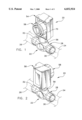
- FIG. 1 is a front perspective view of a valve actuating device of the present invention, the device being threadably secured to a plunger-type valve;
- FIG. 2 is a rear perspective view thereof
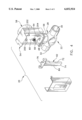
- FIG. 3 is an exploded rear elevational view of a valve member and stem arrangement of the valve and the manner upon which the valve is secured to the valve actuating device;
- FIG. 4 is an exploded rear perspective view of the component parts of the valve actuating device of a first embodiment
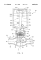
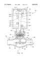
- FIGS. 5 and 6 are cross-sectional views in elevation of the first embodiment of the valve actuating device and the valve with the valve actuating device being illustrated in varying positions of operation.
- valve actuating device 20 for opening and closing a valve, generally indicated at 22.
- the valve 22 is part of a zone heating and/or cooling system having an inlet pipe 24 and an outlet pipe 26, both illustrated in broken lines in FIGS. 1 and 2, for connecting the valve 22 to the system.
- the valve actuating device 20 of the present invention is especially suited for delivering fluid (e.g., water or coolant) to a zone of the system when called upon at a rate which does not cause water hammer and which is not excessively slow.
- the valve 22 is a standard globe valve which is commonly found in such systems.
- the valve 22 comprises a valve housing, generally indicated at 28, which is preferably fabricated from cast bronze.
- the valve housing 28 has an inlet 30 which is suitably connected to the inlet pipe 24 (e.g., soldering) and an outlet 32 which is connected to the outlet pipe 26 in an identical manner.
- the valve housing 28 also includes a fitting receiving formation 34 with an opening 36 formed therein which extends along an axis A generally transverse to an axis B which extends between the inlet 30 and the outlet 32.
- the valve housing 28 is provided with a valve seat 38 formed in a wall 40 that extends between the inlet 30 and the outlet 32.
- the valve seat 38 has an opening 42 formed therein which allows fluid to pass from the inlet 30 to the outlet 32.
- the valve 22 further includes a plunger valve member assembly, generally indicated at 44, which includes a brass fitting 46 having threads for threadably engaging the female threads of the fitting receiving formation 34.
- the brass fitting 46 of the assembly houses a valve stem 48 which is axially movable in an up-and-down direction along axis A.
- a valve member 50 fabricated from any suitable elastomeric material for sealingly engaging the valve seat 38 of the valve housing 28.
- the valve member 50 is circular in plan view and shaped for fully and sealingly engaging the valve seat for blocking the opening 42 formed in wall 40.
- the valve stem 48 can be moved axially along axis A for moving the valve member 50 between a closed position in which the valve member 50 sealingly engages the valve seat 38 for blocking the flow of fluid from the inlet 30 to the outlet 32 (see FIG. 6) and an open position in which the valve member 50 is spaced from the valve seat 38 (see FIG. 5) for allowing fluid to pass from the inlet 30 to the outlet 32.
- the valve stem 48 is biased to its open position by a spring 52 which is illustrated in broken lines.
- Spring 52 is disposed between the bottom of brass fitting 46 and an annular flange 49 on valve stem 48.
- Spring 52 has a length which allows it to be tensionally fit between brass fitting 46 and annular flange 49, to bias the valve stem 48 in its open position.
- spring 52 is compressed between brass fitting 46 and annular flange 49.
- the valve actuating device 20 comprises a generally box-shaped housing, generally indicated at 54.
- the housing 54 includes a fitting or collar 56 having internal threads which, when securing the valve actuating device 20 to the valve 22, threadably engage the outer threads of the fitting receiving formation 34 of the valve 22.
- the device 20 and valve 22 assume the configuration illustrated in FIGS. 1 and 2.
- a motor, generally designated 58, is mounted on an interior wall 60 of the housing 54.
- the motor 58 is provided for reciprocally moving a T-shaped rack, generally indicated at 62, which engages the valve stem 48 of the valve 22 for moving the valve member 50 between its opened and closed positions.
- the motor 58 is a 2-watt bidirectional direct current (D.C.) motor having a shaft 64 which extends through an opening (not designated) formed in the interior wall 60.
- a pinion gear 66 At the outer end of the shaft 64 of the motor 58 is a pinion gear 66 which is adapted to engage the teeth 84 of rack 62 for moving the rack 62 along axis A.
- Motor 58 includes a timing and control circuit (not shown) for controlling the amount of time that power is applied to the motor in order to open and close the valve.
- the timing circuit provides power to the motor 58 for approximately twelve seconds in order to drive pinion gear 66 in the clockwise direction to fully close the valve 22.
- the timing circuit provides power to the motor 58 for approximately ten seconds in order to drive pinion gear 66 in the counterclockwise direction to fully open the valve 22.
- the torque produced by motor 58 when closing the valve 22 is sufficient to overcome the upward force caused by spring 52, as well as the pump head pressure caused by fluid flowing across valve member 38.
- the timing circuit is programmed to power the motor 58 so as to alternate between driving the pinion gear 66 in the clockwise direction, thus allowing the valve to open, and the counterclockwise direction, thus causing the rack 62 to drive the valve stem 48 downward to close the valve 22.
- the timing circuit may be programmed to power the motor for less than the above-indicated times in order to partially close the valve 22. This allows the valve to operate as a modulating valve to regulate the flow of fluid from inlet 30 to outlet 32.
- an upper bearing surface 200 which holds the upper portion of elongate section 72 in position against a bearing surface 202 as rack 162 moves upward and downward
- a lower roller bushing 204 which holds the lower portion of elongate section 72 in position to ensure that teeth 84 remain in engagement with pinion gear 66.
- Bushing 204 may be formed of rubber around a metal core, or any other material which is commonly used in the manufacture of bushings of this type.
- Bearing surfaces 200 and 202 are mounted to back wall 60 and may be formed of metal, plastic or any commonly used low-friction, long wearing material.
- Stops 206 and 208 are mounted to back wall 60 on either side of the upper portion of elongate section 72 in order to limit the travel of rack 62 by providing a contact for cross section 76 at the lower end of travel of the rack 62.
- An upper stop 210 is mounted to the top surface 161 of housing 154 to provide a contact for cross section 76 at the upper end of travel of the rack 62.
- Upper stop 210 is preferably formed from a brass or steel shim, however, a spring or other cushioning material may also be used to form the upper stop 210.
- FIG. 5 shows the valve actuating device in a first position in which the rack 62 is in contact with upper stop 210 and valve 22 is open, due to the upward biasing force of spring 52.
- the timing and control circuit sends power of the correct polarity to motor 58, which turns pinion gear 66 in the clockwise direction.
- the teeth of the pinion gear 66 engage the teeth 84 of rack 62, and the rack is driven downwardly, causing end portion 74 of elongate section 72 to push valve stem 48 downward, thus closing the valve 22, as shown in FIG. 6.
- the motor is energized for approximately twelve seconds during this closing operation. Once the valve is fully closed, power to the motor is stopped and the internal friction of the motor allows pinion gear 66 to hold rack 62 in the downward position, thus maintaining valve 22 in the closed position.
- the timing circuit sends power of the opposite polarity to motor 58, which turns pinion gear 66 in the counterclockwise direction.
- the teeth of the pinion gear 66 engage the teeth 84 of rack 62, and the rack is driven upwardly, causing end portion 74 of elongate section 72 to release valve stem 48, thus allowing the spring 52 to push valve 22 open, as shown in FIG. 5.
- the motor is energized for approximately ten seconds during this opening operation. Once the valve is fully opened, power to the motor is stopped.
- the present invention provides a valve actuating device which, by utilizing a bidirectional D.C. motor, reduces the amount of power required to maintain the valve 22 in the closed position. This reduces the stress on the motor 58, thus extending the operational life of the motor 58. Furthermore, the motor allows the valve to be held partially open in order to regulate the flow of fluid through the valve.
Abstract
Description
Claims (5)
Priority Applications (4)
| Application Number | Priority Date | Filing Date | Title |
|---|---|---|---|
| US09/235,979 US6032924A (en) | 1999-01-22 | 1999-01-22 | Motorized valve actuating device |
| AU25144/00A AU2514400A (en) | 1999-01-22 | 2000-01-21 | Motorized valve actuating device |
| CA002356525A CA2356525A1 (en) | 1999-01-22 | 2000-01-21 | Motorized valve actuating device |
| PCT/US2000/001559 WO2000043701A1 (en) | 1999-01-22 | 2000-01-21 | Motorized valve actuating device |
Applications Claiming Priority (1)
| Application Number | Priority Date | Filing Date | Title |
|---|---|---|---|
| US09/235,979 US6032924A (en) | 1999-01-22 | 1999-01-22 | Motorized valve actuating device |
Publications (1)
| Publication Number | Publication Date |
|---|---|
| US6032924A true US6032924A (en) | 2000-03-07 |
Family
ID=22887637
Family Applications (1)
| Application Number | Title | Priority Date | Filing Date |
|---|---|---|---|
| US09/235,979 Expired - Lifetime US6032924A (en) | 1999-01-22 | 1999-01-22 | Motorized valve actuating device |
Country Status (4)
| Country | Link |
|---|---|
| US (1) | US6032924A (en) |
| AU (1) | AU2514400A (en) |
| CA (1) | CA2356525A1 (en) |
| WO (1) | WO2000043701A1 (en) |
Cited By (25)
| Publication number | Priority date | Publication date | Assignee | Title |
|---|---|---|---|---|
| US6471182B1 (en) * | 2001-07-25 | 2002-10-29 | Mcintosh Douglas S. | Control valves for heating and cooling systems |
| US6471184B1 (en) * | 2001-07-25 | 2002-10-29 | Mcintosh Douglas S. | Spring assisted electric/electronic globe control valve |
| US20030217775A1 (en) * | 2002-03-01 | 2003-11-27 | Cory Cousineau | Fluid valve |
| US20040041113A1 (en) * | 2000-10-30 | 2004-03-04 | Klaus Biester | Isolating device |
| US20040164266A1 (en) * | 2003-01-16 | 2004-08-26 | Wilhelm Lutzer | Mechanism with a push-pull cable for operating a valve in an aircraft |
| US20040246753A1 (en) * | 2001-09-19 | 2004-12-09 | Peter Kunow | DC converter |
| US20040252431A1 (en) * | 2001-09-19 | 2004-12-16 | Peter Kunow | Universal energy supply system |
| US20040262998A1 (en) * | 2001-09-19 | 2004-12-30 | Peter Kunow | Dc voltage converting device |
| US20050013148A1 (en) * | 2001-09-19 | 2005-01-20 | Peter Kunow | Universal power supply system |
| US20050029476A1 (en) * | 2000-05-11 | 2005-02-10 | Cooper Cameron Corporation | Electric control and supply system |
| US20050185349A1 (en) * | 2000-10-30 | 2005-08-25 | Klaus Biester | Control and supply system |
| US20050205819A1 (en) * | 2004-03-17 | 2005-09-22 | William Morrison | Valve for reducing water hammer |
| EP1724504A1 (en) * | 2005-05-17 | 2006-11-22 | Perry Electric S.r.l. | Motor actuator for radiator valve |
| US20070102660A1 (en) * | 2005-11-04 | 2007-05-10 | Denso Corporation | Torque-transmitting device for use in air control valve |
| US20070240676A1 (en) * | 2006-04-12 | 2007-10-18 | Denso Corporation | Throttle control apparatus and method for throttle control |
| US20080190466A1 (en) * | 2007-02-09 | 2008-08-14 | Bruno Gaus | Drain valve |
| US20100244561A1 (en) * | 2001-09-19 | 2010-09-30 | Cameron International Corporation | DC Voltage Converting Device |
| US8074894B2 (en) | 2008-11-18 | 2011-12-13 | Honeywell International Inc. | Secondary mixing valve hot port |
| CN102359640A (en) * | 2011-09-14 | 2012-02-22 | 浙江福禄克燃气仪表有限公司 | Special motor valve for intelligent gas meter control |
| WO2012028153A1 (en) * | 2010-09-01 | 2012-03-08 | Flowcon International A/S | A valve system |
| US8733666B2 (en) | 2008-11-18 | 2014-05-27 | Honeywell International Inc. | Thermostatic mixing valve with tamper resistant adjustment feature |
| US20140326908A1 (en) * | 2011-03-21 | 2014-11-06 | Markus Schober | Valve control device for a vehicle |
| CN108030966A (en) * | 2018-02-05 | 2018-05-15 | 赵明洁 | A kind of intelligence thoracic duction instrument |
| JP2020085057A (en) * | 2018-11-19 | 2020-06-04 | アイシン精機株式会社 | On/off valve |
| US11566725B2 (en) * | 2020-02-18 | 2023-01-31 | Surpass Industry Co., Ltd. | Flow rate regulating device and control method of flow rate regulating device |
Families Citing this family (1)
| Publication number | Priority date | Publication date | Assignee | Title |
|---|---|---|---|---|
| UA109390C2 (en) * | 2015-03-06 | 2015-08-10 | AUTOMATIC GAS FLOW CONTROL SYSTEM |
Citations (10)
| Publication number | Priority date | Publication date | Assignee | Title |
|---|---|---|---|---|
| US2052987A (en) * | 1931-06-17 | 1936-09-01 | Honeywell Regulator Co | Electric valve control |
| US2912215A (en) * | 1957-04-22 | 1959-11-10 | Universal Metals Company | Automatic valve |
| US4318530A (en) * | 1978-11-22 | 1982-03-09 | Lissmyr Per Olof | Valve mechanism with controlled opening means |
| US4551072A (en) * | 1984-02-15 | 1985-11-05 | Hibar Systems Limited | Fluid pressure operated actuator |
| US4807700A (en) * | 1987-09-18 | 1989-02-28 | Cameron Iron Works Usa, Inc. | Wireline downhole annulus valve |
| US4836497A (en) * | 1988-03-08 | 1989-06-06 | Johnson Controls, Inc. | Adjustable valve linkage |
| US4895301A (en) * | 1988-03-09 | 1990-01-23 | Robertshaw Controls Company | Engine coolant system and method of making the same |
| US5145146A (en) * | 1991-04-15 | 1992-09-08 | Yazaki Corporation | Nozzle support arrangement in electromagnetic valve |
| US5529282A (en) * | 1995-03-17 | 1996-06-25 | Sparco Inc. | Valve actuating device of a heating and/or cooling system |
| US5941500A (en) * | 1998-03-24 | 1999-08-24 | Sparco Inc. | Valve actuating device having a reduced impact operating mechanism |
-
1999
- 1999-01-22 US US09/235,979 patent/US6032924A/en not_active Expired - Lifetime
-
2000
- 2000-01-21 WO PCT/US2000/001559 patent/WO2000043701A1/en active Application Filing
- 2000-01-21 AU AU25144/00A patent/AU2514400A/en not_active Abandoned
- 2000-01-21 CA CA002356525A patent/CA2356525A1/en not_active Abandoned
Patent Citations (10)
| Publication number | Priority date | Publication date | Assignee | Title |
|---|---|---|---|---|
| US2052987A (en) * | 1931-06-17 | 1936-09-01 | Honeywell Regulator Co | Electric valve control |
| US2912215A (en) * | 1957-04-22 | 1959-11-10 | Universal Metals Company | Automatic valve |
| US4318530A (en) * | 1978-11-22 | 1982-03-09 | Lissmyr Per Olof | Valve mechanism with controlled opening means |
| US4551072A (en) * | 1984-02-15 | 1985-11-05 | Hibar Systems Limited | Fluid pressure operated actuator |
| US4807700A (en) * | 1987-09-18 | 1989-02-28 | Cameron Iron Works Usa, Inc. | Wireline downhole annulus valve |
| US4836497A (en) * | 1988-03-08 | 1989-06-06 | Johnson Controls, Inc. | Adjustable valve linkage |
| US4895301A (en) * | 1988-03-09 | 1990-01-23 | Robertshaw Controls Company | Engine coolant system and method of making the same |
| US5145146A (en) * | 1991-04-15 | 1992-09-08 | Yazaki Corporation | Nozzle support arrangement in electromagnetic valve |
| US5529282A (en) * | 1995-03-17 | 1996-06-25 | Sparco Inc. | Valve actuating device of a heating and/or cooling system |
| US5941500A (en) * | 1998-03-24 | 1999-08-24 | Sparco Inc. | Valve actuating device having a reduced impact operating mechanism |
Cited By (48)
| Publication number | Priority date | Publication date | Assignee | Title |
|---|---|---|---|---|
| US7615893B2 (en) | 2000-05-11 | 2009-11-10 | Cameron International Corporation | Electric control and supply system |
| US20050029476A1 (en) * | 2000-05-11 | 2005-02-10 | Cooper Cameron Corporation | Electric control and supply system |
| US6978979B2 (en) * | 2000-10-30 | 2005-12-27 | Cooper Cameron Corporation | Isolating device |
| US20040041113A1 (en) * | 2000-10-30 | 2004-03-04 | Klaus Biester | Isolating device |
| US20090296428A1 (en) * | 2000-10-30 | 2009-12-03 | Cameron International Corporation | Control and supply system |
| US7576447B2 (en) | 2000-10-30 | 2009-08-18 | Cameron International Corporation | Control and supply system |
| US20050185349A1 (en) * | 2000-10-30 | 2005-08-25 | Klaus Biester | Control and supply system |
| US8212378B2 (en) | 2000-10-30 | 2012-07-03 | Cameron International Corporation | Control and supply system |
| US20100019573A1 (en) * | 2001-05-07 | 2010-01-28 | Cameron International Corporation | Electric control and supply system |
| US8536731B2 (en) | 2001-05-07 | 2013-09-17 | Cameron International Corporation | Electric control and supply system |
| US6471184B1 (en) * | 2001-07-25 | 2002-10-29 | Mcintosh Douglas S. | Spring assisted electric/electronic globe control valve |
| US6471182B1 (en) * | 2001-07-25 | 2002-10-29 | Mcintosh Douglas S. | Control valves for heating and cooling systems |
| US20040252431A1 (en) * | 2001-09-19 | 2004-12-16 | Peter Kunow | Universal energy supply system |
| US7453170B2 (en) | 2001-09-19 | 2008-11-18 | Cameron International Corporation | Universal energy supply system |
| US8106538B2 (en) | 2001-09-19 | 2012-01-31 | Cameron International Corporation | DC voltage converting device |
| US8106536B2 (en) | 2001-09-19 | 2012-01-31 | Cameron International Corporation | Universal power supply system |
| US7851949B2 (en) | 2001-09-19 | 2010-12-14 | Cameron International Corporation | DC converter |
| US20100244561A1 (en) * | 2001-09-19 | 2010-09-30 | Cameron International Corporation | DC Voltage Converting Device |
| US7433214B2 (en) | 2001-09-19 | 2008-10-07 | Cameron International Corporation | DC converter |
| US8492927B2 (en) | 2001-09-19 | 2013-07-23 | Cameron International Corporation | Universal power supply system |
| US7759827B2 (en) | 2001-09-19 | 2010-07-20 | Cameron International Corporation | DC voltage converting device having a plurality of DC voltage converting units connected in series on an input side and in parallel on an output side |
| US20050013148A1 (en) * | 2001-09-19 | 2005-01-20 | Peter Kunow | Universal power supply system |
| US20040262998A1 (en) * | 2001-09-19 | 2004-12-30 | Peter Kunow | Dc voltage converting device |
| US7683505B2 (en) | 2001-09-19 | 2010-03-23 | Cameron International Corporation | Universal energy supply system |
| US20040246753A1 (en) * | 2001-09-19 | 2004-12-09 | Peter Kunow | DC converter |
| US20030217775A1 (en) * | 2002-03-01 | 2003-11-27 | Cory Cousineau | Fluid valve |
| US20100019930A1 (en) * | 2002-11-12 | 2010-01-28 | Camerson International Corporation | Electric Control and Supply System |
| US8212410B2 (en) | 2002-11-12 | 2012-07-03 | Cameron International Corporation | Electric control and supply system |
| US20040164266A1 (en) * | 2003-01-16 | 2004-08-26 | Wilhelm Lutzer | Mechanism with a push-pull cable for operating a valve in an aircraft |
| US7040600B2 (en) * | 2003-01-16 | 2006-05-09 | Airbus Deutschland Gmbh | Mechanism with a push-pull cable for operating a valve in an aircraft |
| US20050205819A1 (en) * | 2004-03-17 | 2005-09-22 | William Morrison | Valve for reducing water hammer |
| EP1724504A1 (en) * | 2005-05-17 | 2006-11-22 | Perry Electric S.r.l. | Motor actuator for radiator valve |
| US7543794B2 (en) * | 2005-11-04 | 2009-06-09 | Denso Corporation | Torque-transmitting device for use in air control valve |
| US20070102660A1 (en) * | 2005-11-04 | 2007-05-10 | Denso Corporation | Torque-transmitting device for use in air control valve |
| US7669581B2 (en) * | 2006-04-12 | 2010-03-02 | Denso Corporation | Throttle control apparatus and method for throttle control |
| US20070240676A1 (en) * | 2006-04-12 | 2007-10-18 | Denso Corporation | Throttle control apparatus and method for throttle control |
| US20080190466A1 (en) * | 2007-02-09 | 2008-08-14 | Bruno Gaus | Drain valve |
| US8146181B2 (en) * | 2007-02-09 | 2012-04-03 | Meiko Maschinenbau Gmbh & Co. Kg | Drain valve |
| US8733666B2 (en) | 2008-11-18 | 2014-05-27 | Honeywell International Inc. | Thermostatic mixing valve with tamper resistant adjustment feature |
| US8074894B2 (en) | 2008-11-18 | 2011-12-13 | Honeywell International Inc. | Secondary mixing valve hot port |
| WO2012028153A1 (en) * | 2010-09-01 | 2012-03-08 | Flowcon International A/S | A valve system |
| CN103180795A (en) * | 2010-09-01 | 2013-06-26 | 弗洛康国际有限公司 | A valve system |
| US20140326908A1 (en) * | 2011-03-21 | 2014-11-06 | Markus Schober | Valve control device for a vehicle |
| CN102359640B (en) * | 2011-09-14 | 2013-06-05 | 浙江福禄克燃气仪表有限公司 | Special motor valve for intelligent gas meter control |
| CN102359640A (en) * | 2011-09-14 | 2012-02-22 | 浙江福禄克燃气仪表有限公司 | Special motor valve for intelligent gas meter control |
| CN108030966A (en) * | 2018-02-05 | 2018-05-15 | 赵明洁 | A kind of intelligence thoracic duction instrument |
| JP2020085057A (en) * | 2018-11-19 | 2020-06-04 | アイシン精機株式会社 | On/off valve |
| US11566725B2 (en) * | 2020-02-18 | 2023-01-31 | Surpass Industry Co., Ltd. | Flow rate regulating device and control method of flow rate regulating device |
Also Published As
| Publication number | Publication date |
|---|---|
| AU2514400A (en) | 2000-08-07 |
| WO2000043701A1 (en) | 2000-07-27 |
| CA2356525A1 (en) | 2000-07-27 |
Similar Documents
| Publication | Publication Date | Title |
|---|---|---|
| US6032924A (en) | Motorized valve actuating device | |
| US5529282A (en) | Valve actuating device of a heating and/or cooling system | |
| US4979542A (en) | Pulse modulated hydraulic valve | |
| US5474107A (en) | Fail-open solenoid actuated valve | |
| BR9814418A (en) | Fuel injector with ball valve | |
| KR860004266A (en) | Flow control valve and method | |
| US6095485A (en) | Valve actuating device having a reduced impact operating mechanism | |
| US5950984A (en) | Solenoid valve | |
| JP2003343750A (en) | Directly operated pneumatic valve having air assist return | |
| US5941500A (en) | Valve actuating device having a reduced impact operating mechanism | |
| WO1995006835A1 (en) | Fail-open solenoid actuated valve | |
| US7111642B2 (en) | Valve having fast and slow acting closure elements | |
| US6708725B2 (en) | Valve, particularly solenoid valve | |
| JPS627435B2 (en) | ||
| US9140451B2 (en) | Gas tap comprising an electromagnetic safety valve and magnetic insert for an electromagnetic safety valve | |
| ES521749A0 (en) | IMPROVEMENTS IN FAN DRIVES FOR A REFRIGERATION INSTALLATION. | |
| EP1790889B1 (en) | Valve gear | |
| CN108700202B (en) | Solenoid valve and use of a solenoid valve | |
| US5713556A (en) | Composite-action butterfly valve | |
| GB2320311A (en) | Magnetically latched diverter valves | |
| JPH11280946A (en) | Constant flow rate solenoid | |
| US20060081806A1 (en) | Solenoid valve and a solenoid assembly | |
| JPH02245588A (en) | Motor valve and control device thereof | |
| SU593039A1 (en) | Solenoid valve with pilot control | |
| JP2006291856A (en) | Fuel injection valve |
Legal Events
| Date | Code | Title | Description |
|---|---|---|---|
| AS | Assignment |
Owner name: SPARCO INC., RHODE ISLAND Free format text: ASSIGNMENT OF ASSIGNORS INTEREST;ASSIGNOR:CASTLE, ROBERT W.;REEL/FRAME:009843/0721 Effective date: 19990218 |
|
| FEPP | Fee payment procedure |
Free format text: PAYOR NUMBER ASSIGNED (ORIGINAL EVENT CODE: ASPN); ENTITY STATUS OF PATENT OWNER: LARGE ENTITY |
|
| STCF | Information on status: patent grant |
Free format text: PATENTED CASE |
|
| FEPP | Fee payment procedure |
Free format text: PAT HOLDER NO LONGER CLAIMS SMALL ENTITY STATUS, ENTITY STATUS SET TO UNDISCOUNTED (ORIGINAL EVENT CODE: STOL); ENTITY STATUS OF PATENT OWNER: LARGE ENTITY |
|
| REFU | Refund |
Free format text: REFUND - SURCHARGE, PETITION TO ACCEPT PYMT AFTER EXP, UNINTENTIONAL (ORIGINAL EVENT CODE: R2551); ENTITY STATUS OF PATENT OWNER: LARGE ENTITY |
|
| FPAY | Fee payment |
Year of fee payment: 4 |
|
| SULP | Surcharge for late payment | ||
| FPAY | Fee payment |
Year of fee payment: 8 |
|
| FPAY | Fee payment |
Year of fee payment: 12 |
|
| AS | Assignment |
Owner name: JPMORGAN CHASE BANK, N.A., AS ADMINISTRATIVE AGENT, NEW YORK Free format text: SECURITY INTEREST;ASSIGNOR:ADEMCO INC.;REEL/FRAME:047337/0577 Effective date: 20181025 Owner name: JPMORGAN CHASE BANK, N.A., AS ADMINISTRATIVE AGENT Free format text: SECURITY INTEREST;ASSIGNOR:ADEMCO INC.;REEL/FRAME:047337/0577 Effective date: 20181025 |