US6033113A - Seal for zipper-type plastic bags and the like - Google Patents
Seal for zipper-type plastic bags and the like Download PDFInfo
- Publication number
- US6033113A US6033113A US09/136,134 US13613498A US6033113A US 6033113 A US6033113 A US 6033113A US 13613498 A US13613498 A US 13613498A US 6033113 A US6033113 A US 6033113A
- Authority
- US
- United States
- Prior art keywords
- zipper closure
- zipper
- plastic
- plastic bag
- bag
- Prior art date
- Legal status (The legal status is an assumption and is not a legal conclusion. Google has not performed a legal analysis and makes no representation as to the accuracy of the status listed.)
- Expired - Lifetime
Links
Images
Classifications
-
- B—PERFORMING OPERATIONS; TRANSPORTING
- B65—CONVEYING; PACKING; STORING; HANDLING THIN OR FILAMENTARY MATERIAL
- B65D—CONTAINERS FOR STORAGE OR TRANSPORT OF ARTICLES OR MATERIALS, e.g. BAGS, BARRELS, BOTTLES, BOXES, CANS, CARTONS, CRATES, DRUMS, JARS, TANKS, HOPPERS, FORWARDING CONTAINERS; ACCESSORIES, CLOSURES, OR FITTINGS THEREFOR; PACKAGING ELEMENTS; PACKAGES
- B65D33/00—Details of, or accessories for, sacks or bags
- B65D33/16—End- or aperture-closing arrangements or devices
- B65D33/25—Riveting; Dovetailing; Screwing; using press buttons or slide fasteners
- B65D33/2508—Riveting; Dovetailing; Screwing; using press buttons or slide fasteners using slide fasteners with interlocking members having a substantially uniform section throughout the length of the fastener; Sliders therefor
- B65D33/2541—Riveting; Dovetailing; Screwing; using press buttons or slide fasteners using slide fasteners with interlocking members having a substantially uniform section throughout the length of the fastener; Sliders therefor characterised by the slide fastener, e.g. adapted to interlock with a sheet between the interlocking members having sections of particular shape
-
- Y—GENERAL TAGGING OF NEW TECHNOLOGICAL DEVELOPMENTS; GENERAL TAGGING OF CROSS-SECTIONAL TECHNOLOGIES SPANNING OVER SEVERAL SECTIONS OF THE IPC; TECHNICAL SUBJECTS COVERED BY FORMER USPC CROSS-REFERENCE ART COLLECTIONS [XRACs] AND DIGESTS
- Y10—TECHNICAL SUBJECTS COVERED BY FORMER USPC
- Y10S—TECHNICAL SUBJECTS COVERED BY FORMER USPC CROSS-REFERENCE ART COLLECTIONS [XRACs] AND DIGESTS
- Y10S24/00—Buckles, buttons, clasps
- Y10S24/30—Separable-fastener or required component thereof
- Y10S24/50—Separable-fastener or required component thereof including member having elongated, resilient, interlocking face with identical, parallel cross-sections throughout its length
-
- Y—GENERAL TAGGING OF NEW TECHNOLOGICAL DEVELOPMENTS; GENERAL TAGGING OF CROSS-SECTIONAL TECHNOLOGIES SPANNING OVER SEVERAL SECTIONS OF THE IPC; TECHNICAL SUBJECTS COVERED BY FORMER USPC CROSS-REFERENCE ART COLLECTIONS [XRACs] AND DIGESTS
- Y10—TECHNICAL SUBJECTS COVERED BY FORMER USPC
- Y10T—TECHNICAL SUBJECTS COVERED BY FORMER US CLASSIFICATION
- Y10T24/00—Buckles, buttons, clasps, etc.
- Y10T24/45—Separable-fastener or required component thereof [e.g., projection and cavity to complete interlock]
- Y10T24/45152—Each mating member having similarly shaped, sized, and operated interlocking or intermeshable face
- Y10T24/45157—Zipper-type [e.g., slider]
- Y10T24/45168—Zipper-type [e.g., slider] for container [e.g., bag]
Definitions
- This invention relates generally to the improved sealing of plastic containers and, more specifically, to the addition of fillets to a zipper closure for plastic bags and similar containers in order to eliminate gaps formed between the two sides of the zipper closure which allow for leakage of air or liquid, particularly at the side seals of such containers.
- Plastic bags having zipper closures typically consist of two substantially similar-sized sheets of plastic film (usually supplied from a pair of continuous web spools or rolls) which are sealed together at a lower end of the sheets to form a front layer and a rear layer, with the seal forming a bottom edge of the bag (or, alternatively, the plastic bag may be formed by a length of bag film folded over upon itself to form a front layer and a rear layer connected by an integral bottom edge defined by the fold); and two opposing lengths of plastic film heat sealed along the inside of the upper edges of the front and rear layers of bag film, with each of the lengths of plastic film carrying two or more interdependent ridges. The lengths of film appear interdigitated in cross-section due to these interdependent ridges which form the zipper closure. Side edges of the plastic bag are typically sealed using a sealing head.
- escape gaps located at the intersection of the zipper closure, the bag film, and the side edges of the plastic bag. These escape gaps are frequently formed as a result of applying continuous pressure and heat to seal the side edges of the bag, without making accommodations for the underlying zipper closure that is typically already heat sealed along the top edge of the bag film. Such escape gaps facilitate leakage of air and/or liquid directly into or out of the contents of the plastic bag, which can cause undesired spillage, contamination, and spoilage of such contents.
- U.S. Pat. No. 3,986,914 issued to Howard, discloses one method for eliminating the escape gaps at the side edges of the bags, consisting of forming a bead seal at the junction of each outermost ridge of the zipper closure and the side edges of the plastic bag.
- the patent discloses forming the bead seal during heat-welding of the side edges of the plastic bag.
- the bead seal is made of plastic that is forced into the junctions during heating of the container and zipper closure by an apparatus called a pressure bar.
- the specially configured pressure bar includes a U-shaped indentation or channel, disposed so that the walls of the channel straddle and slightly pinch the zipper closure when the pressure bar and a cooperating surface (such as a sealing bar or an anvil) are in contact with one another.
- the U-shaped channel within the pressure bar provides a pressure differential which causes heated plastic to flow into the junctions, thus forming the bead seals.
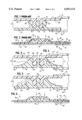
- FIG. 1 shows an enlarged cross-section, rotated 90° for convenience, of a conventional two-part zipper closure member 11 taken along a side edge of a plastic bag 10, just after the bag-making stages wherein the two parts of the zipper closure 12, 16 are respectively heat sealed to the front and rear layers 14, 18 of the bag, and before the sides of the two layers of the zipper closure are melted together (i.e., at the extreme side edges of the plastic bag 10).
- the front part of the zipper closure bearing reference number 12 is adjacent to the front layer 14 of the plastic bag
- the rear part of the zipper closure, bearing reference number 16 is adjacent to the rear layer 18 of the plastic bag.
- FIG. 2 demonstrates the problem of escape gaps present in prior art devices which form in part because the melting of the sides of the zipper closure is typically uneven and cannot be relied upon to completely eliminate escape gaps at the outer ridges of the zipper closure. As a result, air and liquid can still leak out the sides of the plastic bag at the intersection of the bag's side edges and the zipper closure.
- the side edge sealing step which consists of exposing the sides of the bag 10 to a sealing head, the front layer 14 and rear layer 18 of the bag 10 below the zipper closure are sealed together along a seam designated by reference number 20.
- the relatively flat portions 30, 31 and 32, 33 of the zipper closure layers melt together during the side edge sealing step along melt lines 22 and 24.
- escape gaps 34, 36 form, thus allowing leakage of air and liquid through the zipper closure at the side edges of the plastic bag 10.
- One object of the present invention is therefore to eliminate formation of the undesirable escape gaps between the ridges of the zipper closure by providing a means for making the change in profile between the ridge portion of the zipper closure and the rest of the bag film more gradual.
- Another object of the present invention is to provide zipper closures for plastic bags and similar containers that are air-tight and liquid-tight, even along their side edges.
- An additional object of the present invention is to provide a zipper-type plastic bag manufacturing process suitable to practice using existing, conventional heat dies in an in-line web-type process, such that there is no need for the use of a pressure differential-producing die to impart any special profiles to the zipper closure of the plastic bags.
- the present invention achieves an air-tight and liquid-tight zipper closure-type plastic bag by eliminating unwanted escape gaps at the intersection of the zipper closure and the side edges of the bag and across the entire length of the zipper closure.
- the escape gaps are eliminated by adding a mass of material to the zipper closure at the boundaries where such escape gaps otherwise occur.
- the extra mass is composed of the same material as the layers of the zipper closure.
- the extra mass is a co-extruded material that preferably shares at least some characteristics with the material of the layers of the zipper closure, such as low melting point, but also exhibits a higher flow rate than the material of the zipper closure when heated to a liquified state.
- FIG. 1 is an enlarged cross-section of a conventional (prior art) two-part zipper closure member taken along a side edge of a plastic bag prior to heat sealing;
- FIG. 2 is an enlarged cross-section of the conventional (prior art) two-part zipper closure member shown in FIG. 1 after preheating of the zipper closure member and heat sealing of the zipper closure and bag layers;
- FIG. 3 is an enlarged cross-section of the improved zipper closure of the present invention, cut away, having extra mass made of the same material as the layers of the zipper closure in the area where escape gaps would otherwise form;
- FIG. 4 is an enlarged cross-section of an alternate embodiment of the zipper closure of the present invention, cut away, having a co-extruded extra mass made of a different material from the layers of the zipper closure in the area where escape gaps would otherwise form;
- FIG. 5 is an enlarged cross-section of the improved zipper closure of the present invention, with broken lines representing various possible alternate profiles for the extra mass used to eliminate escape gaps;
- FIG. 6 is an enlarged cross-section of the improved zipper closure of the present invention after heat sealing of the sides of the zipper closure and bag layers;
- FIG. 7 is a schematic front plan view of an in-line web assembly of plastic bags having zipper closures sealed thereto;
- FIG. 8 is an exploded cross section, partially cut away, taken along lines 8--8 of FIG. 7, showing the final stages of manufacturing improved zipper closure plastic bags according to the teachings of the present invention.
- the improved zipper closure of the present invention eliminates unwanted escape gaps which otherwise existed at the intersection of conventional zipper closures and the side edges of the bags to which the zipper closures were sealed.
- a conventional zipper closure 11 operates by interlocking fingers 15, 17 along the front layer 12 of the zipper closure 11 with complimentary fingers 13, 26, 28 along the rear layer 16 of the zipper closure 11.
- the relatively flat portions 30, 31 extending along the bottom of zipper closure 11 provide areas of the zipper closure that are used to heat seal the zipper closure 11 to the front and rear layers 14, 18 of the plastic bag 10.
- Flat portions 30, 31 are also melted together along melt line 22 only along the outermost or side edges of the zipper closure 11, as shown in FIG. 2.
- the relatively flat portions 32, 33 which extend along the top of the zipper closure 11 are melted together along melt line 24 only at the side edges of the zipper closure 11, and provide a convenient opening handle along the upper edge of the zipper closed plastic bag.
- the conventional zipper closure 11 suffers from the existence of escape gaps 34 and 36 at the intersection of the zipper closure 11 and the side edges of the plastic bag 10.
- Such an escape gap 34 of prior art zipper closure bag manufacturing processes is particularly troublesome, inasmuch as it permits gas and/or liquid to leak into and out of the interior of plastic bag 10, thus preventing a completely air-tight, liquid-tight sealed environment.
- perishable food products or any other items placed inside the bag 10 for isolation tend to spoil or become contaminated earlier than if the bag 10 did not have the escape gap 34.
- FIG. 3 is a representation of a first embodiment of the present invention (rotated 90°)
- a zipper closure 61 consists of a front layer 52 and a rear layer 54.
- the zipper closure 61 is operated in the conventional manner by interlocking fingers 55, 58 of the rear layer 54 with the corresponding finger 57 of the front layer 52. Only the upper half of the zipper closure 61 is shown in FIG. 3 in order to provide a side-by-side comparison of the first embodiment of the present invention with FIG. 4, which depicts the lower half of a zipper closure in an alternate embodiment of the invention (also rotated 90°).
- the first embodiment eliminates escape gaps by filling the region between the outermost fingers of the rear layer 54, such as finger 58 and the relatively flat portions, such as flat portion 53 of the rear layer 54 of the zipper closure 61 with a fillet 60.
- the location of fillet 60 is advantageously placed where escape gaps would otherwise form.
- the fillet 60 is made of the same plastic material as the zipper closure 61 such as a polyethylene material.
- the outer edge 62 of fillet 60 melts together with the front layer 52 of the zipper closure 61.
- the zipper closure 61 could be flipped such that the fillets 60 are placed onto fingers that are instead located on the front layer of the zipper closure 61.
- the zipper closure could have a design in which there is an outermost finger on each of the two layers of the zipper closure, wherein a fillet 60 would be added to each of the front and the rear layers of the zipper closure without departing from the scope of the present invention.
- FIG. 5 demonstrates that the profile of the fillet 60 may be concave, thus having outer edge 62; or may be inclined, thus having outer edge 64; or may be convex, thus having outer edge 66.
- a heat source such as a sealing head
- each outer fillet edge 62, 64 or 66 will advantageously melt together with the opposing layer 52 of the zipper closure 61 along melt lines 74, 76, as shown in FIG. 6.
- the arrows in FIG. 6 demonstrate the direction in which pressure is applied by the sealing head to seal the side edges of the zipper closure 61 and the side edges of the rear layer 70 and front layer 72 of the plastic bag 50.
- FIG. 4 An alternate embodiment of the present invention is shown in FIG. 4.
- the zipper closure operates in the conventional manner, by interlocking fingers 43, 45 of the rear layer 44 with the finger 47 of the front layer 42 of the zipper closure 41.
- a fillet 46 is added to the zipper closure 41 in the region between the outermost fingers, such as finger 43, and the relatively flat portions of the rear layer 44, such as flat portion 49.
- fillet 46 is made of a different material and is co-extruded with the zipper closure 41.
- polyethylene is a suitable material to use for forming the zipper closure 41.
- fillet 46 is made of a different plastic material that either shares the same flow rate (when heated to a liquid or semi-solid state) as the zipper closure 41, or exhibits higher flow characteristics than the material of the zipper closure 41.
- a suitable such different material for the fillets 60 is a blend of polyurethene and EVA (Ethylene Vinyl Acetate) or a blend of polyethylene and SurlynTM, available from DuPont.
- FIGS. 7 and 8 An exemplary method for manufacturing plastic bags having the improved zipper closures of the present invention is shown in FIGS. 7 and 8.
- a conventional in-line web assembly process incorporates a continuous-feed zipper roll 80, a top web spool 82, and a bottom web spool 84.
- the top web spool 82 continuously supplies front plastic film web 86 to eventually form the front layer 92 of plastic bags 10a, 10b, 10c (see FIG. 8).
- the bottom web spool 84 continuously supplies rear plastic film web 88 to eventually form the rear layer 94 of plastic bags 10a, 10b, 10c.
- the zipper roll 80 continuously feeds a supply of pre-formed, unseparated zipper closures 61.
- the upstream to downstream direction of the manufacturing process is right to left on the drawings, as indicated by the arrows in FIGS. 7 and 8.
- the front layer 52 and rear layer 54 of the continuously fed supply of zipper closures 61 are separated from one another after coming off of the zipper roll 80 by the zipper separator 90.
- the zippers can instead be attached without separating them, for example by staggering the connection points to the front plastic film web 86 and the rear plastic film web 88, or by having the front plastic film web 86 and rear plastic film web 88 located in very close proximity to one another.
- the front layer 52 of the zipper closure 61 is then heat sealed between upper sealing rollers 96, 98 to an upper end of the front plastic film web 86 to eventually form the upper end of the front layer 92 of the plastic bags 10a, 10b, 10c.
- the rear layer 54 of the zipper closure 61 is heat sealed between lower sealing rollers 100, 102 to an upper end of the rear plastic film web 88 to eventually form the upper end of the rear layer 94 of the plastic bags 10a, 10b, 10c.
- rollers 104, 106 provide two functions. First, they provide a means to heat seal a lowermost edge of the plastic film webs 86, 88 to form a bottom edge of the plastic bags 10a, 10b, 10c. Also, rollers 104, 106 re-close the front layer 52 and rear layer 54 of the zipper closure at a locking point 105 before the final stations of the manufacturing process where, among other processing, cutting of the plastic bags 10a, 10b, 10c occurs.
- FIG. 8 downstream of rollers 104, 106 are zipper preheating, and cross sealing/plastic bag cutting stations of the in-line assembly process, both of which are conventional in the art.
- a preheat-crush zone die head 108 is applied to the area of zipper closure 61 where the side heat seal will be applied.
- the preheat-crush zone die head 108 sufficiently melts the fillet material until the fillet material reaches a liquified state, and smashes the profile of the zipper closure in the area where the side edges of the bags 10a, 10b, 10c will be located.
- the pre-heat crush zone die head 108 thus provides a pre-heating means and may take the form of an ultrasonic heat source, a resistive heat source (e.g., an electric coil), or any other heating element that can be used to repeatedly provide heat to a concentrated area for a short duration of time.
- a resistive heat source e.g., an electric coil
- the fillet material is either formed integrally with the zipper closure 61, or alternatively, is co-extruded with the zipper closure upstream of the zipper separator 90.
- the fillet material is preferably made of a blend of polyurethane and EVA, which exhibits a higher flow rate when heated to a liquid state than the plastic (e.g. polyethylene) used to form the zipper closure.
- the higher relative flow rate of the polyurethane causes the fillets to better fill the areas around the upper and lower edges of the zipper closure 61 where escape gaps would otherwise normally be formed.
- Dashed line 109 represents the region where bags 10b and 10c will soon be sealed along their adjoining side edge, then cut by the cross sealing/plastic bag cutting station 110.
- the pre-heat crush zone die head 108 is located at the upper edge of the web films 86, 88 along the dashed line 109 and is intermittently brought into contact with the zipper closure 61 so as to pre-heat an intersection of the zipper closure 61 and the front and rear layers 92, 94 at a location where the outermost or side edges of adjacent bags, e.g., bags 10b and 10c, will be formed once separated from one another along the web.
- the preheat crush zone die head 108 is positioned a fixed distance from the cross sealing/plastic bag cutting station 110, with that fixed distance being equal to the width of one of the bags 10a, 10b, 10c.
- the web films 86, 88 are preferably brought to a rest long enough to allow the pre-heat crush zone die head 108 and the cross sealing/plastic bag cutting station 110 to contact the web films 86, 88 and perform their respective functions.
- the preheat crush zone die head 108 and the cross sealing/plastic bag cutting station 110 may act in tandem, repeatedly simultaneously performing their respective functions on the web films 86, 88, while located a fixed distance from one another.
- This distance is known in the art as “one repeat,” since it is intended to take exactly one cycle of the web films 86, 88 advancing and stopping for the work area of the web films 86, 88 (shown by dashed line 109) to travel from the pre-heat crush zone die head 108 to the cross sealing/plastic bag cutting station 110.
- the cross sealing/plastic bag cutting station 110 provides a side heat seal to form the side edges 92, 94 of the plastic bags 10a, 10b, 10c, as well as seal the left and right side edges of the zipper closure.
- a sharp blade 112 (or, alternatively, a hot wire) in the cross sealing/plastic bag cutting station 110 severs adjacent bags apart from one another by cutting through the center of the side heat seal once formed.
- the resulting plastic bag, e.g. bag 10a is thus formed having no unwanted escape gaps, thereby greatly enhancing the bag's ability to keep food products within the bag fresh (i.e., avoiding early spoilage of the bag's contents).
Abstract
Description
Claims (3)
Priority Applications (1)
| Application Number | Priority Date | Filing Date | Title |
|---|---|---|---|
| US09/136,134 US6033113A (en) | 1998-08-18 | 1998-08-18 | Seal for zipper-type plastic bags and the like |
Applications Claiming Priority (1)
| Application Number | Priority Date | Filing Date | Title |
|---|---|---|---|
| US09/136,134 US6033113A (en) | 1998-08-18 | 1998-08-18 | Seal for zipper-type plastic bags and the like |
Publications (1)
| Publication Number | Publication Date |
|---|---|
| US6033113A true US6033113A (en) | 2000-03-07 |
Family
ID=22471454
Family Applications (1)
| Application Number | Title | Priority Date | Filing Date |
|---|---|---|---|
| US09/136,134 Expired - Lifetime US6033113A (en) | 1998-08-18 | 1998-08-18 | Seal for zipper-type plastic bags and the like |
Country Status (1)
| Country | Link |
|---|---|
| US (1) | US6033113A (en) |
Cited By (41)
| Publication number | Priority date | Publication date | Assignee | Title |
|---|---|---|---|---|
| US6185796B1 (en) * | 1999-08-20 | 2001-02-13 | Illinois Tool Works Inc. | Vacuum seal reclosable zipper |
| US6581253B2 (en) * | 2001-09-14 | 2003-06-24 | Erkenbrack Kenneth Beresford | Fluid-tight container seal |
| US6721999B2 (en) | 2001-04-30 | 2004-04-20 | Absolute Closure Innovations, Inc. | Device for creating a seal between fabrics or other materials |
| US20040091179A1 (en) * | 2002-11-13 | 2004-05-13 | Brent Anderson | Seal for zippered bag |
| US20040159658A1 (en) * | 2003-02-14 | 2004-08-19 | Mclaughlin Michael Ray | Packages, packaging systems, methods for packaging and apparatus for packaging |
| US20040204303A1 (en) * | 1999-10-12 | 2004-10-14 | Com-Pac International, Inc. | Reclosable fastener profile seal and method of forming a fastener profile assembly |
| US20050211319A1 (en) * | 2004-03-23 | 2005-09-29 | Kobetsky Robert G | Leakproof one-way valve for use with vacuum attachment |
| US20060037180A1 (en) * | 2001-04-30 | 2006-02-23 | Absolute Closure Innovations, Inc. | Device for creating a seal between fabrics or other materials |
| US20060093242A1 (en) * | 2004-07-21 | 2006-05-04 | Anzini David J | Reclosable packages for vacuum, pressure and/or liquid containment |
| US20060107500A1 (en) * | 2004-10-25 | 2006-05-25 | Absolute Closure Innovations, Inc. | Device for creating a seal between fabrics or other materials |
| US20060111226A1 (en) * | 2004-07-21 | 2006-05-25 | Anzini David J | Methods of making reclosable packages for vacuum, pressure and/or liquid containment |
| US20060131328A1 (en) * | 2004-12-22 | 2006-06-22 | Brent Anderson | One way valve and container |
| US20060131339A1 (en) * | 2004-12-22 | 2006-06-22 | Brent Anderson | One way valve for fluid evacuation from a container |
| US20060165316A1 (en) * | 2005-01-24 | 2006-07-27 | Intelli Innovations Ltd. | Zip lock |
| US20060196019A1 (en) * | 1999-10-12 | 2006-09-07 | Com-Pac International, Inc. | Vibratory molding process and product |
| US20060199465A1 (en) * | 2005-03-03 | 2006-09-07 | Brent Anderson | Enhanced balloon weight system |
| US20060201626A1 (en) * | 1999-10-12 | 2006-09-14 | Wright Donald K | Method of sealing reclosable fasteners |
| US20060285773A1 (en) * | 2005-06-15 | 2006-12-21 | Shaffer Gregory R | Plastic biodegradable reclosable zipper for flexible packages |
| US20060285778A1 (en) * | 2005-06-01 | 2006-12-21 | May Timothy J | Recloseable zipper with sealant on inner and outer surfaces of closure members |
| US20070065336A1 (en) * | 2005-09-19 | 2007-03-22 | Scheffrahn Rudolf H | Method for storing food during fumigation |
| US20070086682A1 (en) * | 1999-10-12 | 2007-04-19 | Com-Pac International, Inc. | Airtight reclosable fastener |
| US20080022496A1 (en) * | 2006-06-28 | 2008-01-31 | Ben Meager | Device for creating a seal between fabrics or other materials |
| US20080124008A1 (en) * | 2006-11-19 | 2008-05-29 | Ben Meager | Devices and methods for forming a closure between fabrics and/or other materials |
| US20080271298A1 (en) * | 2007-01-11 | 2008-11-06 | Benjamin Meager | Device for creating a seal between fabrics and/or other materials and methods of making and using the same |
| US20090211852A1 (en) * | 2007-09-25 | 2009-08-27 | Hannon Gregory E | Self-lubricating fasteners |
| US20090232423A1 (en) * | 2008-03-14 | 2009-09-17 | Azad Sabounjian | Valve for vacuum storage bag |
| US20090324141A1 (en) * | 2008-06-25 | 2009-12-31 | Dais Brian C | Reclosable vacuum-tight pouch and resealable vacuum-tight closure mechanism therefor |
| US7784160B2 (en) | 2007-03-16 | 2010-08-31 | S.C. Johnson & Son, Inc. | Pouch and airtight resealable closure mechanism therefor |
| US7857515B2 (en) | 2007-06-15 | 2010-12-28 | S.C. Johnson Home Storage, Inc. | Airtight closure mechanism for a reclosable pouch |
| US7874731B2 (en) | 2007-06-15 | 2011-01-25 | S.C. Johnson Home Storage, Inc. | Valve for a recloseable container |
| US7886412B2 (en) | 2007-03-16 | 2011-02-15 | S.C. Johnson Home Storage, Inc. | Pouch and airtight resealable closure mechanism therefor |
| US7887238B2 (en) | 2007-06-15 | 2011-02-15 | S.C. Johnson Home Storage, Inc. | Flow channels for a pouch |
| US7946766B2 (en) | 2007-06-15 | 2011-05-24 | S.C. Johnson & Son, Inc. | Offset closure mechanism for a reclosable pouch |
| US7967509B2 (en) | 2007-06-15 | 2011-06-28 | S.C. Johnson & Son, Inc. | Pouch with a valve |
| US20110235951A1 (en) * | 1998-07-17 | 2011-09-29 | Com-Pac International, Inc. | Reclosable bag with tear open feature |
| US20120036684A1 (en) * | 2004-08-19 | 2012-02-16 | Paul Tilman | High-integrity closure |
| US8397958B2 (en) | 2010-08-05 | 2013-03-19 | Ds Smith Plastics Limited | Closure valve assembly for a container |
| US8875356B2 (en) | 2011-10-06 | 2014-11-04 | Intercontinental Great Brands Llc | Mechanical and adhesive based reclosable fasteners |
| US20170066561A1 (en) * | 2014-02-25 | 2017-03-09 | Mark Steele | Package having a lap or fin seal without an air gap formed adjacent the seal |
| USD845761S1 (en) | 2018-01-17 | 2019-04-16 | Hms Mfg. Co. | Closure clip |
| US20190225383A1 (en) * | 2017-03-31 | 2019-07-25 | Inteplast Group Corporation | Plastic bag zipper closure with sealing projections |
Citations (15)
| Publication number | Priority date | Publication date | Assignee | Title |
|---|---|---|---|---|
| US34117A (en) * | 1862-01-07 | John mcevoy | ||
| US2144755A (en) * | 1937-01-11 | 1939-01-24 | Eugene L Alexander | Closure device |
| US3338285A (en) * | 1963-11-23 | 1967-08-29 | Asf Gleitverschulss Gmbh | Package or wrapper of plastic material |
| US3339606A (en) * | 1966-06-14 | 1967-09-05 | Kugler Emanuel | Slide closure |
| US3395788A (en) * | 1967-04-17 | 1968-08-06 | Truman F. Gill | Lure container with self-contained tension retained closure |
| US3986914A (en) * | 1972-02-11 | 1976-10-19 | Uly-Pak, Inc. | Heat-sealing method for plastic containers |
| US4484352A (en) * | 1983-02-07 | 1984-11-20 | Katzin Lawrence F | Reclosable plastic bag |
| US4523918A (en) * | 1982-11-12 | 1985-06-18 | Minigrip, Inc. | Method of forming a bag chain |
| US4755248A (en) * | 1986-12-30 | 1988-07-05 | The Dow Chemical Company | Slot-cast intergrated interlocking film closure structure |
| US4822539A (en) * | 1987-09-14 | 1989-04-18 | Minigrip, Inc. | Method of and apparatus for extruding bag making material having fastener profiles and alignment ribs, with reinforcing and stabilizing beam effect ridge means |
| US4909017A (en) * | 1989-07-28 | 1990-03-20 | Minigrip, Inc. | Reclosable bag material, method and apparatus |
| US4925318A (en) * | 1988-10-17 | 1990-05-15 | Schurpack, Inc. | Packing, method of manufacturing same, and strip material therefor |
| US5059036A (en) * | 1990-04-27 | 1991-10-22 | Kapak Corporation | Vented pouch arrangement and method |
| US5141577A (en) * | 1990-05-18 | 1992-08-25 | Dowbrands L.P. | Closure for reclosable thermoplastic containers |
| US5878468A (en) * | 1996-05-22 | 1999-03-09 | Reynolds Consumer Products, Inc. | Closure arrangement for reclosable bag and method thereof |
-
1998
- 1998-08-18 US US09/136,134 patent/US6033113A/en not_active Expired - Lifetime
Patent Citations (16)
| Publication number | Priority date | Publication date | Assignee | Title |
|---|---|---|---|---|
| US34117A (en) * | 1862-01-07 | John mcevoy | ||
| US2144755A (en) * | 1937-01-11 | 1939-01-24 | Eugene L Alexander | Closure device |
| US3338285A (en) * | 1963-11-23 | 1967-08-29 | Asf Gleitverschulss Gmbh | Package or wrapper of plastic material |
| US3339606A (en) * | 1966-06-14 | 1967-09-05 | Kugler Emanuel | Slide closure |
| US3395788A (en) * | 1967-04-17 | 1968-08-06 | Truman F. Gill | Lure container with self-contained tension retained closure |
| US3986914A (en) * | 1972-02-11 | 1976-10-19 | Uly-Pak, Inc. | Heat-sealing method for plastic containers |
| US4523918A (en) * | 1982-11-12 | 1985-06-18 | Minigrip, Inc. | Method of forming a bag chain |
| US4484352A (en) * | 1983-02-07 | 1984-11-20 | Katzin Lawrence F | Reclosable plastic bag |
| US4755248A (en) * | 1986-12-30 | 1988-07-05 | The Dow Chemical Company | Slot-cast intergrated interlocking film closure structure |
| US4822539A (en) * | 1987-09-14 | 1989-04-18 | Minigrip, Inc. | Method of and apparatus for extruding bag making material having fastener profiles and alignment ribs, with reinforcing and stabilizing beam effect ridge means |
| US4925318A (en) * | 1988-10-17 | 1990-05-15 | Schurpack, Inc. | Packing, method of manufacturing same, and strip material therefor |
| US4909017A (en) * | 1989-07-28 | 1990-03-20 | Minigrip, Inc. | Reclosable bag material, method and apparatus |
| US4909017B1 (en) * | 1989-07-28 | 1999-02-09 | Minigrip Inc | Reclosable bag material method and apparatus |
| US5059036A (en) * | 1990-04-27 | 1991-10-22 | Kapak Corporation | Vented pouch arrangement and method |
| US5141577A (en) * | 1990-05-18 | 1992-08-25 | Dowbrands L.P. | Closure for reclosable thermoplastic containers |
| US5878468A (en) * | 1996-05-22 | 1999-03-09 | Reynolds Consumer Products, Inc. | Closure arrangement for reclosable bag and method thereof |
Cited By (85)
| Publication number | Priority date | Publication date | Assignee | Title |
|---|---|---|---|---|
| US20110235951A1 (en) * | 1998-07-17 | 2011-09-29 | Com-Pac International, Inc. | Reclosable bag with tear open feature |
| US6185796B1 (en) * | 1999-08-20 | 2001-02-13 | Illinois Tool Works Inc. | Vacuum seal reclosable zipper |
| US20060196019A1 (en) * | 1999-10-12 | 2006-09-07 | Com-Pac International, Inc. | Vibratory molding process and product |
| US20070086682A1 (en) * | 1999-10-12 | 2007-04-19 | Com-Pac International, Inc. | Airtight reclosable fastener |
| US8002467B2 (en) * | 1999-10-12 | 2011-08-23 | Com-Pac International, Inc. | Reclosable fastener profile seal and method of forming a fastener profile assembly |
| US8506745B2 (en) | 1999-10-12 | 2013-08-13 | Donald K. Wright | Method of sealing reclosable fasteners |
| US20060201626A1 (en) * | 1999-10-12 | 2006-09-14 | Wright Donald K | Method of sealing reclosable fasteners |
| US7337507B2 (en) | 1999-10-12 | 2008-03-04 | Com-Pac International | Zipper tape having a reclosable portion and a planar portion |
| US20040204303A1 (en) * | 1999-10-12 | 2004-10-14 | Com-Pac International, Inc. | Reclosable fastener profile seal and method of forming a fastener profile assembly |
| US6721999B2 (en) | 2001-04-30 | 2004-04-20 | Absolute Closure Innovations, Inc. | Device for creating a seal between fabrics or other materials |
| US20040187273A1 (en) * | 2001-04-30 | 2004-09-30 | Absolute Closure Innovations, Inc. | Device for creating a seal between fabrics or other materials |
| US20060037180A1 (en) * | 2001-04-30 | 2006-02-23 | Absolute Closure Innovations, Inc. | Device for creating a seal between fabrics or other materials |
| US20090089983A1 (en) * | 2001-04-30 | 2009-04-09 | Ben Meager | Device for creating a seal between fabrics or other materials |
| US7703184B2 (en) | 2001-04-30 | 2010-04-27 | Gore Enterprise Holdings, Inc. | Device for creating a seal between fabrics or other materials |
| US20090199369A1 (en) * | 2001-04-30 | 2009-08-13 | Ben Meager | Device For Creating A Seal Between Fabrics or Other Materials |
| US7451530B2 (en) | 2001-04-30 | 2008-11-18 | Gore Enterprise Holdings, Inc. | Device for creating a seal between fabrics or other materials |
| US7536758B2 (en) | 2001-04-30 | 2009-05-26 | Gore Enterprise Holdings, Inc. | Device for creating a seal between fabrics or other materials |
| US6581253B2 (en) * | 2001-09-14 | 2003-06-24 | Erkenbrack Kenneth Beresford | Fluid-tight container seal |
| WO2004043793A2 (en) * | 2002-11-13 | 2004-05-27 | Cti Industries Corporation | Seal for zippered bag |
| WO2004043793A3 (en) * | 2002-11-13 | 2004-09-30 | Cti Ind Corp | Seal for zippered bag |
| US20040091179A1 (en) * | 2002-11-13 | 2004-05-13 | Brent Anderson | Seal for zippered bag |
| US8469591B2 (en) * | 2002-11-13 | 2013-06-25 | Cti Industries Corporation | Seal for zippered bag |
| US20080044112A1 (en) * | 2002-11-13 | 2008-02-21 | Cti Industries Corporation | Seal for zippered bag |
| US7305742B2 (en) * | 2002-11-13 | 2007-12-11 | Cti Industries Corporation | Seal for zippered bag |
| US20060272960A1 (en) * | 2003-02-14 | 2006-12-07 | Mclaughlin Michael R | Packages, packaging systems, methods for packaging and apparatus for packaging |
| US7958696B2 (en) | 2003-02-14 | 2011-06-14 | Eastman Chemical Company | Packages, packaging systems, methods for packaging and apparatus for packaging |
| US20070022718A1 (en) * | 2003-02-14 | 2007-02-01 | Mclaughlin Michael R | Packages, packaging systems, methods for packaging and apparatus for packaging |
| US7739857B2 (en) | 2003-02-14 | 2010-06-22 | Eastman Chemical Company | Packages, packaging systems, methods for packaging and apparatus for packaging |
| US9598184B2 (en) | 2003-02-14 | 2017-03-21 | Eastman Chemical Company | Method for packaging fiber material |
| US8671652B2 (en) | 2003-02-14 | 2014-03-18 | Eastman Chemical Company | Packages, packaging systems, methods for packaging and apparatus for packaging |
| US20040159658A1 (en) * | 2003-02-14 | 2004-08-19 | Mclaughlin Michael Ray | Packages, packaging systems, methods for packaging and apparatus for packaging |
| US20100236194A1 (en) * | 2003-02-14 | 2010-09-23 | Eastman Chemical Company | Packages, packaging systems, methods for packaging and apparatus for packaging |
| US20110203228A1 (en) * | 2003-02-14 | 2011-08-25 | Eastman Chemical Company | Packages, packaging systems, methods for packaging and apparatus for packaging |
| US7350541B2 (en) | 2004-03-23 | 2008-04-01 | Illinois Tool Works Inc. | Leakproof one-way valve for use with vacuum attachment |
| US20050211319A1 (en) * | 2004-03-23 | 2005-09-29 | Kobetsky Robert G | Leakproof one-way valve for use with vacuum attachment |
| WO2005104721A2 (en) * | 2004-04-26 | 2005-11-10 | Com-Pac International, Inc. | Reclosable fastener profile seal and method of forming a fastener profile assembly |
| WO2005104721A3 (en) * | 2004-04-26 | 2007-11-01 | Compac Int Inc | Reclosable fastener profile seal and method of forming a fastener profile assembly |
| US20060093242A1 (en) * | 2004-07-21 | 2006-05-04 | Anzini David J | Reclosable packages for vacuum, pressure and/or liquid containment |
| US7527585B2 (en) | 2004-07-21 | 2009-05-05 | Illinois Tool Works Inc. | Methods of making reclosable packages for vacuum, pressure and/or liquid containment |
| US20060111226A1 (en) * | 2004-07-21 | 2006-05-25 | Anzini David J | Methods of making reclosable packages for vacuum, pressure and/or liquid containment |
| US20120036684A1 (en) * | 2004-08-19 | 2012-02-16 | Paul Tilman | High-integrity closure |
| US7574780B2 (en) | 2004-10-25 | 2009-08-18 | Gore Enterprise Holdings, Inc. | Device for creating a seal between fabrics or other materials |
| US20060107500A1 (en) * | 2004-10-25 | 2006-05-25 | Absolute Closure Innovations, Inc. | Device for creating a seal between fabrics or other materials |
| US20060131328A1 (en) * | 2004-12-22 | 2006-06-22 | Brent Anderson | One way valve and container |
| US20060131339A1 (en) * | 2004-12-22 | 2006-06-22 | Brent Anderson | One way valve for fluid evacuation from a container |
| US20080230429A1 (en) * | 2004-12-22 | 2008-09-25 | Brent Anderson | One way valve for fluid evacuation from a container |
| US7398953B2 (en) | 2004-12-22 | 2008-07-15 | Cti Industries, Inc. | One way valve for fluid evacuation from a container |
| US7972064B2 (en) | 2004-12-22 | 2011-07-05 | Cti Industries Corporation | One way valve and container |
| US7552907B2 (en) | 2004-12-22 | 2009-06-30 | Cti Industries, Inc. | One way valve for fluid evacuation from a container |
| US20060165316A1 (en) * | 2005-01-24 | 2006-07-27 | Intelli Innovations Ltd. | Zip lock |
| US7674152B2 (en) | 2005-03-03 | 2010-03-09 | Cti Industries, Inc. | Enhanced balloon weight system |
| US20060199465A1 (en) * | 2005-03-03 | 2006-09-07 | Brent Anderson | Enhanced balloon weight system |
| US7758242B2 (en) * | 2005-06-01 | 2010-07-20 | Reynolds Consumer Products, Inc. | Recloseable zipper with sealant on inner and outer surfaces of closure members |
| US20060285778A1 (en) * | 2005-06-01 | 2006-12-21 | May Timothy J | Recloseable zipper with sealant on inner and outer surfaces of closure members |
| US20060285773A1 (en) * | 2005-06-15 | 2006-12-21 | Shaffer Gregory R | Plastic biodegradable reclosable zipper for flexible packages |
| US20070065336A1 (en) * | 2005-09-19 | 2007-03-22 | Scheffrahn Rudolf H | Method for storing food during fumigation |
| US7832065B2 (en) | 2006-06-28 | 2010-11-16 | Gore Enterprise Holdings, Inc. | Device for creating a seal between fabrics or other materials |
| US20080022496A1 (en) * | 2006-06-28 | 2008-01-31 | Ben Meager | Device for creating a seal between fabrics or other materials |
| US20080124008A1 (en) * | 2006-11-19 | 2008-05-29 | Ben Meager | Devices and methods for forming a closure between fabrics and/or other materials |
| US20080271298A1 (en) * | 2007-01-11 | 2008-11-06 | Benjamin Meager | Device for creating a seal between fabrics and/or other materials and methods of making and using the same |
| US8827556B2 (en) | 2007-03-16 | 2014-09-09 | S.C. Johnson & Son, Inc. | Pouch and airtight resealable closure mechanism therefor |
| US8176604B2 (en) | 2007-03-16 | 2012-05-15 | S.C. Johnson & Son, Inc. | Pouch and airtight resealable closure mechanism therefor |
| US7784160B2 (en) | 2007-03-16 | 2010-08-31 | S.C. Johnson & Son, Inc. | Pouch and airtight resealable closure mechanism therefor |
| US7886412B2 (en) | 2007-03-16 | 2011-02-15 | S.C. Johnson Home Storage, Inc. | Pouch and airtight resealable closure mechanism therefor |
| US7887238B2 (en) | 2007-06-15 | 2011-02-15 | S.C. Johnson Home Storage, Inc. | Flow channels for a pouch |
| US7874731B2 (en) | 2007-06-15 | 2011-01-25 | S.C. Johnson Home Storage, Inc. | Valve for a recloseable container |
| US8231273B2 (en) | 2007-06-15 | 2012-07-31 | S.C. Johnson & Son, Inc. | Flow channel profile and a complementary groove for a pouch |
| US7857515B2 (en) | 2007-06-15 | 2010-12-28 | S.C. Johnson Home Storage, Inc. | Airtight closure mechanism for a reclosable pouch |
| US7946766B2 (en) | 2007-06-15 | 2011-05-24 | S.C. Johnson & Son, Inc. | Offset closure mechanism for a reclosable pouch |
| US7967509B2 (en) | 2007-06-15 | 2011-06-28 | S.C. Johnson & Son, Inc. | Pouch with a valve |
| US20090211852A1 (en) * | 2007-09-25 | 2009-08-27 | Hannon Gregory E | Self-lubricating fasteners |
| US8066433B2 (en) | 2008-03-14 | 2011-11-29 | Pro-Mart Industries, Inc. | Valve for vacuum storage bag |
| US20090232423A1 (en) * | 2008-03-14 | 2009-09-17 | Azad Sabounjian | Valve for vacuum storage bag |
| US10597198B2 (en) | 2008-06-25 | 2020-03-24 | S. C. Johnson & Son, Inc. | Reclosable vacuum-tight pouch and resealable vacuum-tight closure mechanism therefor |
| US20090324141A1 (en) * | 2008-06-25 | 2009-12-31 | Dais Brian C | Reclosable vacuum-tight pouch and resealable vacuum-tight closure mechanism therefor |
| US8820591B2 (en) | 2010-08-05 | 2014-09-02 | Ds Smith Plastics Limited | Closure valve assembly for a container |
| US8973789B2 (en) | 2010-08-05 | 2015-03-10 | Ds Smith Plastics Limited | Closure valve assembly for a container |
| US8397958B2 (en) | 2010-08-05 | 2013-03-19 | Ds Smith Plastics Limited | Closure valve assembly for a container |
| US8875356B2 (en) | 2011-10-06 | 2014-11-04 | Intercontinental Great Brands Llc | Mechanical and adhesive based reclosable fasteners |
| US20170066561A1 (en) * | 2014-02-25 | 2017-03-09 | Mark Steele | Package having a lap or fin seal without an air gap formed adjacent the seal |
| US10093457B2 (en) * | 2014-02-25 | 2018-10-09 | Mark Steele | Package having a lap or fin seal without an air gap formed adjacent the seal |
| US11235910B2 (en) | 2014-02-25 | 2022-02-01 | Mark Steele | Package having a lap or fin seal gap elimination feature |
| US20190225383A1 (en) * | 2017-03-31 | 2019-07-25 | Inteplast Group Corporation | Plastic bag zipper closure with sealing projections |
| US10683142B2 (en) * | 2017-03-31 | 2020-06-16 | Inteplast Group Corporation | Plastic bag zipper closure with sealing projections |
| USD845761S1 (en) | 2018-01-17 | 2019-04-16 | Hms Mfg. Co. | Closure clip |
Similar Documents
| Publication | Publication Date | Title |
|---|---|---|
| US6033113A (en) | Seal for zipper-type plastic bags and the like | |
| EP0622169B1 (en) | Method of forming side seams for zippered bags or packages | |
| US5906438A (en) | Flexible pouch-type package having recloseable closure | |
| CA2070937C (en) | Reclosable plastic bags and method of making same utilizing discontinuous zipper profile disposed along a continuous carrier strip | |
| US4663915A (en) | Method of packaging and apparatus | |
| EP0959013B1 (en) | Transverse direction zipper tape | |
| US4894975A (en) | Method and apparatus for making reclosable bags with fastener strips in a form fill and seal machine | |
| EP0985605B1 (en) | Transverse zipper system | |
| US4589145A (en) | Packaging material and package | |
| US5564259A (en) | Method and apparatus for resealable closure addition to form, fill and seal bag | |
| US6017412A (en) | Method for attaching reclosable zipper strip transversely to thermoplastic film material | |
| US6993886B2 (en) | Method for sealing zipper assembly to bag making film at three or more points | |
| AU722974B2 (en) | Pinch-grip zipper | |
| US6986920B2 (en) | Composite web for making gusseted packages | |
| US6371644B1 (en) | Reclosable seal, package, method and apparatus | |
| CN101437727B (en) | Packing bags for reclosing pour spout by slide operation and manufacture method thereof | |
| EP1033317B1 (en) | Crush resistant zipper | |
| US4892512A (en) | Method of making reclosable flexible containers having fastener profiles affixed to exterior of bag walls | |
| US20010043763A1 (en) | Multi-layered freezer storage bag | |
| US7351188B2 (en) | Hooded reclosable packages and related methods of manufacture | |
| US7415810B2 (en) | Methods of manufacturing hooded slider-operated zippered bags | |
| US6994470B2 (en) | Aesthetically pleasing snap closure for flexible packages with means for facilitating automated application to flexible packages, flexible packages including the same, and apparatus for applying snap closures to flexible packages | |
| US6896950B2 (en) | Composite web for making resealable packages and reclosable seals | |
| EP1144253B1 (en) | Method for producing a resealable pouch | |
| WO1994009979A1 (en) | Method for manufacturing a film, a bag made from a film, such a film, and use of the film |
Legal Events
| Date | Code | Title | Description |
|---|---|---|---|
| AS | Assignment |
Owner name: CTI INDUSTRIES CORPORATION, ILLINOIS Free format text: ASSIGNMENT OF ASSIGNORS INTEREST;ASSIGNOR:ANDERSON, BRENT G.;REEL/FRAME:009454/0581 Effective date: 19980824 |
|
| STCF | Information on status: patent grant |
Free format text: PATENTED CASE |
|
| AS | Assignment |
Owner name: CONGRESS FINANCIAL CORPORATION (CENTRAL), ILLINOIS Free format text: SECURITY INTEREST;ASSIGNOR:CTI INDUSTRIES CORPORATION;REEL/FRAME:011474/0154 Effective date: 20010112 |
|
| FPAY | Fee payment |
Year of fee payment: 4 |
|
| FEPP | Fee payment procedure |
Free format text: PAYOR NUMBER ASSIGNED (ORIGINAL EVENT CODE: ASPN); ENTITY STATUS OF PATENT OWNER: SMALL ENTITY |
|
| AS | Assignment |
Owner name: COLE TAYLOR BANK, ILLINOIS Free format text: SECURITY INTEREST;ASSIGNORS:CTI INDUSTRIES CORPORATION;CTI HELIUM, INC.;REEL/FRAME:014934/0051 Effective date: 20031231 |
|
| REMI | Maintenance fee reminder mailed | ||
| FPAY | Fee payment |
Year of fee payment: 8 |
|
| SULP | Surcharge for late payment |
Year of fee payment: 7 |
|
| AS | Assignment |
Owner name: HARRIS N.A.,ILLINOIS Free format text: SECURITY AGREEMENT;ASSIGNOR:CTI INDUSTRIES CORPORATION;REEL/FRAME:024320/0317 Effective date: 20100429 Owner name: HARRIS N.A., ILLINOIS Free format text: SECURITY AGREEMENT;ASSIGNOR:CTI INDUSTRIES CORPORATION;REEL/FRAME:024320/0317 Effective date: 20100429 |
|
| FPAY | Fee payment |
Year of fee payment: 12 |
|
| AS | Assignment |
Owner name: BMO PRIVATE EQUITY (U.S.), INC., ILLINOIS Free format text: SECURITY AGREEMENT;ASSIGNOR:CTI INDUSTRIES CORPORATION;REEL/FRAME:028584/0400 Effective date: 20120717 |
|
| AS | Assignment |
Owner name: CTI INDUSTRIES CORPORATION, ILLINOIS Free format text: RELEASE BY SECURED PARTY;ASSIGNOR:COLE TAYLOR BANK;REEL/FRAME:029640/0128 Effective date: 20120731 |
|
| AS | Assignment |
Owner name: PNC BANK, NATIONAL ASSOCIATION, AS AGENT, PENNSYLV Free format text: SECURITY INTEREST;ASSIGNOR:CTI INDUSTRIES CORPORATION;REEL/FRAME:044397/0761 Effective date: 20171214 Owner name: CTI INDUSTRIES CORPORATION, ILLINOIS Free format text: RELEASE BY SECURED PARTY;ASSIGNOR:BMO HARRIS BANK N.A. (FORMERLY KNOWN AS HARRIS N.A.);REEL/FRAME:044402/0764 Effective date: 20171214 Owner name: CTI INDUSTRIES CORPORATION, ILLINOIS Free format text: RELEASE BY SECURED PARTY;ASSIGNOR:BMO PRIVATE EQUITY (U.S.), INC.;REEL/FRAME:044889/0406 Effective date: 20171214 |
|
| AS | Assignment |
Owner name: YUNHONG CTI LTD. (F/K/A CTI INDUSTRIES CORPORATION), ILLINOIS Free format text: RELEASE BY SECURED PARTY;ASSIGNOR:PNC BANK, NATIONAL ASSOCIATION, AS AGENT;REEL/FRAME:057957/0984 Effective date: 20210930 |
|
| AS | Assignment |
Owner name: CTI INDUSTRIES CORPORATION, ILLINOIS Free format text: RELEASE BY SECURED PARTY;ASSIGNOR:PNC BANK, NATIONAL ASSOCIATION, AS AGENT;REEL/FRAME:058022/0084 Effective date: 20211104 |
|
| AS | Assignment |
Owner name: CTI INDUSTRIES CORPORATION, ILLINOIS Free format text: RELEASE BY SECURED PARTY;ASSIGNOR:PNC BANK, NATIONAL ASSOCIATION, AS AGENT;REEL/FRAME:058072/0807 Effective date: 20211108 |