US6033154A - Waste processing attachment and method for environmentally treating a waste lagoon - Google Patents
Waste processing attachment and method for environmentally treating a waste lagoon Download PDFInfo
- Publication number
- US6033154A US6033154A US09/129,287 US12928798A US6033154A US 6033154 A US6033154 A US 6033154A US 12928798 A US12928798 A US 12928798A US 6033154 A US6033154 A US 6033154A
- Authority
- US
- United States
- Prior art keywords
- waste
- bucket
- lagoon
- working arm
- vehicle
- Prior art date
- Legal status (The legal status is an assumption and is not a legal conclusion. Google has not performed a legal analysis and makes no representation as to the accuracy of the status listed.)
- Expired - Fee Related
Links
- 239000002699 waste material Substances 0.000 title claims abstract description 100
- 238000000034 method Methods 0.000 title claims description 7
- 239000000463 material Substances 0.000 claims abstract description 29
- 229910000831 Steel Inorganic materials 0.000 claims description 5
- 239000010959 steel Substances 0.000 claims description 5
- 239000003153 chemical reaction reagent Substances 0.000 description 32
- 239000010802 sludge Substances 0.000 description 21
- 239000002002 slurry Substances 0.000 description 13
- 239000007787 solid Substances 0.000 description 6
- XLYOFNOQVPJJNP-UHFFFAOYSA-N water Substances O XLYOFNOQVPJJNP-UHFFFAOYSA-N 0.000 description 4
- 239000000428 dust Substances 0.000 description 3
- 239000000203 mixture Substances 0.000 description 3
- 239000004568 cement Substances 0.000 description 2
- 239000010881 fly ash Substances 0.000 description 2
- 238000003860 storage Methods 0.000 description 2
- 238000005273 aeration Methods 0.000 description 1
- 239000006227 byproduct Substances 0.000 description 1
- 238000004140 cleaning Methods 0.000 description 1
- 238000010276 construction Methods 0.000 description 1
- 230000007613 environmental effect Effects 0.000 description 1
- 238000011065 in-situ storage Methods 0.000 description 1
- 239000007788 liquid Substances 0.000 description 1
- 238000012856 packing Methods 0.000 description 1
- 239000011241 protective layer Substances 0.000 description 1
- 239000002910 solid waste Substances 0.000 description 1
- 238000010408 sweeping Methods 0.000 description 1
Images
Classifications
-
- E—FIXED CONSTRUCTIONS
- E02—HYDRAULIC ENGINEERING; FOUNDATIONS; SOIL SHIFTING
- E02F—DREDGING; SOIL-SHIFTING
- E02F3/00—Dredgers; Soil-shifting machines
- E02F3/04—Dredgers; Soil-shifting machines mechanically-driven
- E02F3/88—Dredgers; Soil-shifting machines mechanically-driven with arrangements acting by a sucking or forcing effect, e.g. suction dredgers
- E02F3/8816—Mobile land installations
- E02F3/8825—Mobile land installations wherein at least a part of the soil-shifting equipment is mounted on a dipper-arm, backhoes or the like
-
- E—FIXED CONSTRUCTIONS
- E02—HYDRAULIC ENGINEERING; FOUNDATIONS; SOIL SHIFTING
- E02F—DREDGING; SOIL-SHIFTING
- E02F3/00—Dredgers; Soil-shifting machines
- E02F3/04—Dredgers; Soil-shifting machines mechanically-driven
- E02F3/28—Dredgers; Soil-shifting machines mechanically-driven with digging tools mounted on a dipper- or bucket-arm, i.e. there is either one arm or a pair of arms, e.g. dippers, buckets
- E02F3/36—Component parts
- E02F3/40—Dippers; Buckets ; Grab devices, e.g. manufacturing processes for buckets, form, geometry or material of buckets
-
- E—FIXED CONSTRUCTIONS
- E02—HYDRAULIC ENGINEERING; FOUNDATIONS; SOIL SHIFTING
- E02F—DREDGING; SOIL-SHIFTING
- E02F3/00—Dredgers; Soil-shifting machines
- E02F3/04—Dredgers; Soil-shifting machines mechanically-driven
- E02F3/88—Dredgers; Soil-shifting machines mechanically-driven with arrangements acting by a sucking or forcing effect, e.g. suction dredgers
- E02F3/8808—Stationary installations, e.g. installations using spuds or other stationary supports
-
- E—FIXED CONSTRUCTIONS
- E02—HYDRAULIC ENGINEERING; FOUNDATIONS; SOIL SHIFTING
- E02F—DREDGING; SOIL-SHIFTING
- E02F3/00—Dredgers; Soil-shifting machines
- E02F3/04—Dredgers; Soil-shifting machines mechanically-driven
- E02F3/88—Dredgers; Soil-shifting machines mechanically-driven with arrangements acting by a sucking or forcing effect, e.g. suction dredgers
- E02F3/90—Component parts, e.g. arrangement or adaptation of pumps
- E02F3/92—Digging elements, e.g. suction heads
- E02F3/9212—Mechanical digging means, e.g. suction wheels, i.e. wheel with a suction inlet attached behind the wheel
-
- E—FIXED CONSTRUCTIONS
- E02—HYDRAULIC ENGINEERING; FOUNDATIONS; SOIL SHIFTING
- E02F—DREDGING; SOIL-SHIFTING
- E02F5/00—Dredgers or soil-shifting machines for special purposes
- E02F5/22—Dredgers or soil-shifting machines for special purposes for making embankments; for back-filling
- E02F5/223—Dredgers or soil-shifting machines for special purposes for making embankments; for back-filling for back-filling
- E02F5/226—Dredgers or soil-shifting machines for special purposes for making embankments; for back-filling for back-filling with means for processing the soil, e.g. screening belts, separators; Padding machines
Definitions
- This invention relates to a waste processing attachment for a self-propelled vehicle, such as an industrial excavator, and a method for environmentally treating solid, semi-solid, and liquid sludge waste.
- waste is commonly generated as a by-product of industrial plants, and then stored in man-made lagoons for subsequent treatment.
- the invention discharges sludge-hardening reagent to a predetermined target area below the surface of the lagoon, and mixes the reagent and waste together. The resulting mixture causes the lagoon to harden over a period of about 7-21 days.
- the solidified lagoon is capped with a protective layer and used as a parking lot, equipment storage area, or the like.
- a reagent slurry is pumped from a remote location to a backhoe excavator, and then discharged into the sludge lagoon.
- the excavator includes a reagent injector fork with hollow tines attached to the stick for injecting and mixing the reagent slurring into the sludge waste.
- the operator repetitively rakes the fork through the sludge until a sufficient amount of reagent is mixed into the area being treated.
- the prior art system discharges the reagent slurry over a relatively large area, and randomly mixes by raking the fork through the lagoon.
- the prior art system does not discharge to a predetermined target area, and does not capture and mix the reagent slurry immediately as it enters the sludge waste. Random discharge of reagent and mixing in the above manner would typically result in poorly treated areas having non-uniform hardness and consistency.
- a self-propelled vehicle with a waste processing attachment The vehicle is adapted for being moved over a supporting surface, and has a moveable working arm for reaching outwardly from the vehicle and downwardly beneath an adjacent surface of a waste lagoon.
- the waste processing attachment injects and mixes a waste processing material into the lagoon.
- the attachment includes a bucket mounted on a free end of the moveable working arm, and having a plurality of spaced-apart waste sifting openings.
- a material delivery line extends along the working arm of the vehicle, and has a connecting end connected to a material supply source and a discharge end residing proximate the bucket. Waste processing material flowing through and exiting the delivery line beneath the surface of the waste lagoon is discharged into a target area directly adjacent the bucket and mixed with the waste as the bucket is carried by the working arm through the lagoon.
- the waste sifting openings include an arrangement of relatively small, spaced-apart holes formed in the bucket.
- the waste sifting openings further include a second arrangement of relatively large spaced-apart slots formed in the bucket.
- the open area defined by each slot is at least 4 times greater that the open area defined by each hole.
- the open area defined by each hole is between 8 and 10 square inches.
- the open area defined by each slot is between 40 and 50 square inches.
- a plurality of teeth are formed along a bottom edge of the bucket to facilitate movement of the bucket into and through the waste lagoon.
- the vehicle is a backhoe excavator.
- the material delivery line includes a section of steel pipe mounted to the working arm of the vehicle and terminating at a point adjacent to and forward of the bucket.
- a method for environmentally treating a waste lagoon uses a self-propelled vehicle adapted for movement over a supporting surface, and having a moveable working arm for reaching outwardly from the vehicle and downwardly beneath an adjacent surface of the waste lagoon.
- the method includes the steps of mounting a bucket on a free end of the moveable working arm.
- the bucket has a plurality of spaced-apart waste sifting openings.
- the discharge end of a material delivery line is located proximate the bucket, and is connected at its opposite end to a material supply source.
- the working arm is manipulated to move the bucket into and through the lagoon while simultaneously delivering waste processing material from the supply source through the delivery line to a target area directly adjacent the bucket.
- the working arm and bucket cooperate to mix the processing material and waste together to environmentally treat the lagoon.
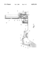
- FIG. 1 is an environmental view of a waste processing attachment according to one preferred embodiment of the invention, and showing the attachment secured to the moveable working arm of a vehicle;
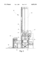
- FIG. 2 is an elevational view of the reagent batch plant
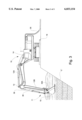
- FIG. 3 is an elevational view of the waste processing attachment and vehicle, and showing the mixing bucket submerged beneath the surface of the sludge waste lagoon;
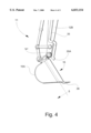
- FIG. 4 is a fragmentary view of the working arm of the vehicle, and showing the location of the reagent delivery line relative to the mixing bucket;
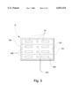
- FIG. 5 is a cross-sectional view taken substantially along line 5--5 at the mouth of the bucket, and looking inwardly to show the arrangement of waste sifting openings formed in the bucket.
- FIG. 1 a self-propelled vehicle including a waste processing attachment according to the present invention is illustrated in FIG. 1, and shown generally at reference numeral 10.
- the waste processing attachment is shown generally at numeral 11.
- the vehicle 10 includes a movable working arm 12 with a pivotably attached boom 12A and stick 12B controlled by an operator in the vehicle cab 14.
- the waste processing attachment 11 is secured to the working arm 12, and includes a mixing bucket 15 mounted on a free end of the stick 12B and carried by the working arm 12 outwardly from the cab 14 and downwardly beneath the surface of a sludge waste lagoon "L".
- Timber mats 16 or other suitable structure are laid over the ground surface adjacent the lagoon "L” to support the vehicle 10 during operation of the working arm 12.
- the vehicle 10 is a standard industrial excavator, such as the CAT 375L manufactured by Caterpillar, Inc. of Aurora, Ill.
- a reagent batch plant 20 is located remote from the vehicle 10, and includes a storage silo 22 with separate compartments for storing fly ash and cement. Each compartment includes two 4-inch diameter aeration pipes to prevent material packing, and promote outward flow of material through open discharge valves and into respective weigh batchers 23 and 24.
- a vacuum line 25 is connected to a dust vent formed in the silo 22, and extends to a freestanding, continuous-cleaning dust collector 26 for controlling the amount material dust entrained in the atmosphere within and around the silo 22.
- a water holding tank 27 is mounted adjacent the silo 22, and includes a water weigh batcher 28 and delivery hose 29 extending from the batcher 28 to a horizontal shaft ribbon mixer 30.
- the mixer 30 is described in further detail in U.S. Pat. No. 4,854,711 incorporated herein by reference.
- the fly ash and cement are discharged from respective batchers 23 and 24 into the mixer 30 and combined and mixed with the water to create a reagent slurry having about one part water and two parts reagent.
- the reagent slurry is stored in a supply hopper 32, and conveyed by a slurry pump 34 from the hopper 32 through a delivery line 35 to the vehicle 10.
- the pump 34 is preferably capable of conveying reagent slurry through 4000 feet of delivery line 35.
- the delivery line 35 is formed in sections of 4-inch diameter steel pipe extending from the supply hopper 32 to the pump 34 to the vehicle 10, and preferably includes quick connect flanges and couplers at every 15 feet of pipe length.
- the length of delivery line 35 at the vehicle 10 and extending along the boom 12A is formed of 4-inch diameter flexible hose to allow free movement of the working arm 12 into and about the lagoon "L".
- a final section of delivery line 35 is formed of 4-inch diameter steel pipe which is welded directly to the stick 12B of the working arm 12 and connected to the flexible hose section by a coupler 36.
- the steel pipe construction at the stick 12B protects the delivery line 35 from damage caused by contacting solid or semi-solid masses contained in the lagoon "L" during treatment.
- the discharge end 35A of the delivery line 35 is centrally located at the mouth of the bucket 15, and is angled slightly to discharge reagent slurry to a predetermined target area directly adjacent to and forward of the bucket 15.
- the lagoon "L” is preferably divided in notional cells, and treated from the bottom up in a series of sweeping lifts extending from a far side of the cell to a near side of the cell. The depth of the cells in some areas of the lagoon may be from 20 to 25 feet.
- the reagent slurry causes the sludge waste to harden over a period of about 7 to 21 days.
- the mixing bucket 15 is mounted on the free end of the stick 12B, and is pivotable a forward and rearward direction about a fixed point "P".
- a number of teeth 38 formed along a bottom edge of the bucket 15 facilitate its movement into and through the sludge lagoon "L".
- the teeth 38 are especially applicable for breaking up larger masses of solid and semi-solid waste.
- the contoured wall 15A of the bucket 15 extending from a top edge to the bottom edge includes a plurality of spaced-apart waste sifting openings 40 adapted for sifting and mixing the sludge waste as the bucket 15 is pulled through the lagoon "L".
- the bucket 15 immediately captures reagent slurry discharged into the target area, uniformly mixes the reagent and sludge waste together, and then passes the treated mixture through the openings 40 as further untreated waste moves into the target area.
- the openings 40 create a slight vacuum force on a back side of the bucket 15 which helps contain the reagent slurry in the target area during mixing. Moreover, the openings 40 sift the waste and help break up larger masses for more effective processing.
- a first set of openings 40 includes relatively small holes 40A formed primarily in a center portion of the bucket 15. According to one embodiment, the diameter of each hole is about 31/2 inches.
- a second set of openings 40 includes relatively large spaced-apart slots 40B formed on either side of the holes 40A. The dimension of each slot is about 13 inches by 31/2 inches.
- the larger slots 40B are closer to respective opposing side walls 15B and 15C of the bucket 15, and allow increased passage of reagent and sludge waste through the bucket 15 after mixing.
- the side walls 15B and 15C are preferably solid.
Abstract
A self-propelled vehicle includes a waste processing attachment. The vehicle is adapted for being moved over a supporting surface, and has a moveable working arm for reaching outwardly from the vehicle and downwardly beneath an adjacent surface of a waste lagoon. The waste processing attachment injects and mixes a waste processing material into the lagoon. The attachment includes a bucket mounted on a free end of the moveable working arm, and having a plurality of spaced-apart waste sifting openings. A material delivery line extends along the working arm of the vehicle, and has a connecting end connected to a material supply source and a discharge end residing proximate the bucket. Waste processing material flowing through and exiting the delivery line beneath the surface of the waste lagoon is discharged into a target area directly adjacent the bucket and mixed with the waste as the bucket is carried by the working arm through the lagoon.
Description
This invention relates to a waste processing attachment for a self-propelled vehicle, such as an industrial excavator, and a method for environmentally treating solid, semi-solid, and liquid sludge waste. Such waste is commonly generated as a by-product of industrial plants, and then stored in man-made lagoons for subsequent treatment. The invention discharges sludge-hardening reagent to a predetermined target area below the surface of the lagoon, and mixes the reagent and waste together. The resulting mixture causes the lagoon to harden over a period of about 7-21 days. After treatment, the solidified lagoon is capped with a protective layer and used as a parking lot, equipment storage area, or the like.
According to one prior art waste treatment system, a reagent slurry is pumped from a remote location to a backhoe excavator, and then discharged into the sludge lagoon. In lieu of a bucket, the excavator includes a reagent injector fork with hollow tines attached to the stick for injecting and mixing the reagent slurring into the sludge waste. As reagent flows through the injector tines, the operator repetitively rakes the fork through the sludge until a sufficient amount of reagent is mixed into the area being treated.
Unlike the invention, the prior art system discharges the reagent slurry over a relatively large area, and randomly mixes by raking the fork through the lagoon. The prior art system does not discharge to a predetermined target area, and does not capture and mix the reagent slurry immediately as it enters the sludge waste. Random discharge of reagent and mixing in the above manner would typically result in poorly treated areas having non-uniform hardness and consistency.
Therefore, it is an object of the invention to provide a waste processing attachment for a vehicle which efficiently and effectively treats sludge waste.
It is another object of the invention to provide a waste processing attachment for a vehicle which treats sludge waste in situ.
It is another object of the invention to provide a waste processing attachment for a vehicle which provides direct delivery of reagent below grade to a predetermined target area.
It is another object of the invention to provide a waste processing attachment for a vehicle which immediately captures and mixes the reagent slurry as it enters the sludge waste.
It is another object of the invention to provide a waste processing attachment for a vehicle which allows precise control of the amount of reagent delivered to the sludge lagoon.
It is another object of the invention to provide a waste processing attachment for a vehicle which provides more efficient, uniform mixing of the reagent and biochemicals with the sludge waste.
It is another object of the invention to provide a waste processing attachment for a vehicle which reduces the quantity of reagent required to treat a given area.
It is another object of the invention to provide a waste processing attachment for a vehicle which produces better consistency in the solidified treated area.
It is another object of the invention to provide a waste processing attachment for a vehicle which discharges and holds reagent in a target area until uniformly mixed with the sludge waste.
It is another object of the invention to provide a method for environmentally treating a sludge waste lagoon.
These and other objects of the present invention are achieved in the preferred embodiments disclosed below by providing a self-propelled vehicle with a waste processing attachment. The vehicle is adapted for being moved over a supporting surface, and has a moveable working arm for reaching outwardly from the vehicle and downwardly beneath an adjacent surface of a waste lagoon. The waste processing attachment injects and mixes a waste processing material into the lagoon. The attachment includes a bucket mounted on a free end of the moveable working arm, and having a plurality of spaced-apart waste sifting openings. A material delivery line extends along the working arm of the vehicle, and has a connecting end connected to a material supply source and a discharge end residing proximate the bucket. Waste processing material flowing through and exiting the delivery line beneath the surface of the waste lagoon is discharged into a target area directly adjacent the bucket and mixed with the waste as the bucket is carried by the working arm through the lagoon.
According to one preferred embodiment of the invention, the waste sifting openings include an arrangement of relatively small, spaced-apart holes formed in the bucket.
According to yet another preferred embodiment of the invention, the waste sifting openings further include a second arrangement of relatively large spaced-apart slots formed in the bucket.
According to yet another preferred embodiment of the invention, the open area defined by each slot is at least 4 times greater that the open area defined by each hole.
According to yet another preferred embodiment of the invention, the open area defined by each hole is between 8 and 10 square inches.
According to yet another preferred embodiment of the invention, the open area defined by each slot is between 40 and 50 square inches.
According to yet another preferred embodiment of the invention, a plurality of teeth are formed along a bottom edge of the bucket to facilitate movement of the bucket into and through the waste lagoon.
According to yet another preferred embodiment of the invention, the vehicle is a backhoe excavator.
According to yet another preferred embodiment of the invention, the material delivery line includes a section of steel pipe mounted to the working arm of the vehicle and terminating at a point adjacent to and forward of the bucket.
A method for environmentally treating a waste lagoon uses a self-propelled vehicle adapted for movement over a supporting surface, and having a moveable working arm for reaching outwardly from the vehicle and downwardly beneath an adjacent surface of the waste lagoon. The method includes the steps of mounting a bucket on a free end of the moveable working arm. The bucket has a plurality of spaced-apart waste sifting openings. The discharge end of a material delivery line is located proximate the bucket, and is connected at its opposite end to a material supply source. The working arm is manipulated to move the bucket into and through the lagoon while simultaneously delivering waste processing material from the supply source through the delivery line to a target area directly adjacent the bucket. The working arm and bucket cooperate to mix the processing material and waste together to environmentally treat the lagoon.
Some of the objects of the invention have been set forth above. Other objects and advantages of the invention will appear as the description proceeds when taken in conjunction with the following drawings, in which:
FIG. 1 is an environmental view of a waste processing attachment according to one preferred embodiment of the invention, and showing the attachment secured to the moveable working arm of a vehicle;
FIG. 2 is an elevational view of the reagent batch plant;
FIG. 3 is an elevational view of the waste processing attachment and vehicle, and showing the mixing bucket submerged beneath the surface of the sludge waste lagoon;
FIG. 4 is a fragmentary view of the working arm of the vehicle, and showing the location of the reagent delivery line relative to the mixing bucket; and
FIG. 5 is a cross-sectional view taken substantially along line 5--5 at the mouth of the bucket, and looking inwardly to show the arrangement of waste sifting openings formed in the bucket.
Referring now specifically to the drawings, a self-propelled vehicle including a waste processing attachment according to the present invention is illustrated in FIG. 1, and shown generally at reference numeral 10. The waste processing attachment is shown generally at numeral 11. The vehicle 10 includes a movable working arm 12 with a pivotably attached boom 12A and stick 12B controlled by an operator in the vehicle cab 14. The waste processing attachment 11 is secured to the working arm 12, and includes a mixing bucket 15 mounted on a free end of the stick 12B and carried by the working arm 12 outwardly from the cab 14 and downwardly beneath the surface of a sludge waste lagoon "L". Timber mats 16 or other suitable structure are laid over the ground surface adjacent the lagoon "L" to support the vehicle 10 during operation of the working arm 12. According to one preferred embodiment, the vehicle 10 is a standard industrial excavator, such as the CAT 375L manufactured by Caterpillar, Inc. of Aurora, Ill.
As shown in FIGS. 1 and 2, a reagent batch plant 20 is located remote from the vehicle 10, and includes a storage silo 22 with separate compartments for storing fly ash and cement. Each compartment includes two 4-inch diameter aeration pipes to prevent material packing, and promote outward flow of material through open discharge valves and into respective weigh batchers 23 and 24. A vacuum line 25 is connected to a dust vent formed in the silo 22, and extends to a freestanding, continuous-cleaning dust collector 26 for controlling the amount material dust entrained in the atmosphere within and around the silo 22.
A water holding tank 27 is mounted adjacent the silo 22, and includes a water weigh batcher 28 and delivery hose 29 extending from the batcher 28 to a horizontal shaft ribbon mixer 30. The mixer 30 is described in further detail in U.S. Pat. No. 4,854,711 incorporated herein by reference. The fly ash and cement are discharged from respective batchers 23 and 24 into the mixer 30 and combined and mixed with the water to create a reagent slurry having about one part water and two parts reagent. The reagent slurry is stored in a supply hopper 32, and conveyed by a slurry pump 34 from the hopper 32 through a delivery line 35 to the vehicle 10. The pump 34 is preferably capable of conveying reagent slurry through 4000 feet of delivery line 35.
As best shown in FIGS. 1 and 3, the delivery line 35 is formed in sections of 4-inch diameter steel pipe extending from the supply hopper 32 to the pump 34 to the vehicle 10, and preferably includes quick connect flanges and couplers at every 15 feet of pipe length. The length of delivery line 35 at the vehicle 10 and extending along the boom 12A is formed of 4-inch diameter flexible hose to allow free movement of the working arm 12 into and about the lagoon "L". A final section of delivery line 35 is formed of 4-inch diameter steel pipe which is welded directly to the stick 12B of the working arm 12 and connected to the flexible hose section by a coupler 36. The steel pipe construction at the stick 12B protects the delivery line 35 from damage caused by contacting solid or semi-solid masses contained in the lagoon "L" during treatment.
As shown in FIG. 4, the discharge end 35A of the delivery line 35 is centrally located at the mouth of the bucket 15, and is angled slightly to discharge reagent slurry to a predetermined target area directly adjacent to and forward of the bucket 15. As the bucket 15 is pulled by the working arm 12 through the lagoon "L" in a direction towards the vehicle 10, the reagent slurry exiting the delivery line 35 is immediately captured by the bucket 15 and mixed with the sludge waste. The lagoon "L" is preferably divided in notional cells, and treated from the bottom up in a series of sweeping lifts extending from a far side of the cell to a near side of the cell. The depth of the cells in some areas of the lagoon may be from 20 to 25 feet. After treatment, the reagent slurry causes the sludge waste to harden over a period of about 7 to 21 days.
Referring to FIGS. 4 and 5, the mixing bucket 15 is mounted on the free end of the stick 12B, and is pivotable a forward and rearward direction about a fixed point "P". A number of teeth 38 formed along a bottom edge of the bucket 15 facilitate its movement into and through the sludge lagoon "L". The teeth 38 are especially applicable for breaking up larger masses of solid and semi-solid waste.
As shown in FIG. 5, the contoured wall 15A of the bucket 15 extending from a top edge to the bottom edge includes a plurality of spaced-apart waste sifting openings 40 adapted for sifting and mixing the sludge waste as the bucket 15 is pulled through the lagoon "L". The bucket 15 immediately captures reagent slurry discharged into the target area, uniformly mixes the reagent and sludge waste together, and then passes the treated mixture through the openings 40 as further untreated waste moves into the target area. The openings 40 create a slight vacuum force on a back side of the bucket 15 which helps contain the reagent slurry in the target area during mixing. Moreover, the openings 40 sift the waste and help break up larger masses for more effective processing.
A first set of openings 40 includes relatively small holes 40A formed primarily in a center portion of the bucket 15. According to one embodiment, the diameter of each hole is about 31/2 inches. A second set of openings 40 includes relatively large spaced-apart slots 40B formed on either side of the holes 40A. The dimension of each slot is about 13 inches by 31/2 inches. As the bucket 15 sweeps through the lagoon "L", the arrangement of smaller holes 40A in the center of the bucket 15 and closer to the discharge end 35A of the delivery line 35 promotes more uniform mixing of reagent and sludge waste by limiting direct passage of reagent through the bucket 15. The larger slots 40B are closer to respective opposing side walls 15B and 15C of the bucket 15, and allow increased passage of reagent and sludge waste through the bucket 15 after mixing. The side walls 15B and 15C are preferably solid.
A waste processing attachment for a backhoe excavator is described above. Various details of the invention may be changed without departing from its scope. Furthermore, the foregoing description of the preferred embodiment of the invention and the best mode for practicing the invention are provided for the purpose of illustration only and not for the purpose of limitation--the invention being defined by the claims.
Claims (19)
1. In combination with a self-propelled vehicle for being moved over a supporting surface, and having a moveable working arm adapted for reaching outwardly from said vehicle and downwardly beneath an adjacent surface of a waste lagoon, a waste processing attachment for injecting and mixing a waste processing material into the lagoon, said waste processing attachment comprising:
(a) a bucket mounted on a free end of the moveable working arm, and including a plurality of spaced-apart waste sifting openings therein;
(b) a material delivery line extending along the working arm of said vehicle, and having a connecting end connected to a material supply source and a discharge end residing proximate said bucket, whereby waste processing material passing through and exiting said delivery line beneath the surface of the waste lagoon is discharged into a target area directly adjacent said bucket and mixed with the waste as said bucket is carried by the working arm through the lagoon.
2. A combination according to claim 1, wherein said waste sifting openings comprise an arrangement of relatively small, spaced-apart holes formed in said bucket.
3. A combination according to claim 1, wherein said waste sifting openings comprise an arrangement of relatively large spaced-apart slots formed in said bucket.
4. A combination according to claim 1, wherein said waste sifting openings formed in said bucket comprise a first arrangement of relatively small spaced-apart holes and a second arrangement of relatively large spaced-apart slots.
5. A combination according to claim 4, wherein the open area defined by each slot is at least 4 times greater that the open area defined by each hole.
6. A combination according to claim 2, wherein the open area defined by each hole is between 8 and 10 square inches.
7. A combination according to claim 3, wherein the open area defined by each slot is between 40 and 50 square inches.
8. A combination according to claim 1, and comprising a plurality of teeth formed along a bottom edge of said bucket to facilitate movement of said bucket into and through the waste lagoon.
9. A combination according to claim 1, wherein said vehicle comprises a backhoe excavator.
10. A combination according to claim 1, wherein said material delivery line includes a section of steel pipe mounted to the working arm of said vehicle and terminating at a point adjacent to and forward of said bucket.
11. A waste processing attachment for use in combination with a self-propelled vehicle, the vehicle being adapted for movement over a supporting surface and having a moveable working arm for reaching outwardly from the vehicle and downwardly beneath an adjacent surface of a waste lagoon, said waste processing attachment comprising:
(a) a bucket for being mounted on a free end of the moveable working arm, and including a plurality of spaced-apart waste sifting openings therein; and
(b) material delivery means for delivering waste processing material to a target area directly adjacent said bucket, such that waste processing material injected by said delivery means beneath the surface of the lagoon is mixed with the waste as said bucket is moved by the working arm through the lagoon.
12. A waste processing attachment according to claim 11, wherein said waste sifting openings comprise an arrangement of relatively small, spaced-apart holes formed in said bucket.
13. A waste processing attachment according to claim 11, wherein said waste sifting openings comprise an arrangement of relatively large spaced-apart slots formed in said bucket.
14. A combination according to claim 11, wherein said waste sifting openings formed in said bucket comprise a first arrangement of relatively small spaced-apart holes and a second arrangement of relatively large spaced-apart slots.
15. A waste processing attachment according to claim 14, wherein the open area defined by each slot is at least 4 times greater that the open area defined by each hole.
16. A waste processing attachment according to claim 12, wherein the open area defined by each hole is between 8 and 10 square inches.
17. A waste processing attachment according to claim 13, wherein the open area defined by each slot is between 40 and 50 square inches.
18. A waste processing attachment according to claim 11, and comprising a plurality of teeth formed along a bottom edge of said bucket to facilitate movement of said bucket into and through the waste lagoon.
19. A method for environmentally treating a waste lagoon using a self-propelled vehicle adapted for movement over a supporting surface and having a moveable working arm for reaching outwardly from the vehicle and downwardly beneath an adjacent surface of the waste lagoon, said method comprising the steps of:
(a) mounting a bucket on a free end of the moveable working arm, the bucket having a plurality of spaced-apart waste sifting openings therein;
(b) locating a discharge end of a material delivery line proximate the bucket, and connecting an opposite end of the material delivery to a material supply source;
and
(c) manipulating the working arm to move the bucket into and through the lagoon while simultaneously delivering waste processing material from the supply source through the delivery line to a target area directly adjacent said bucket, whereby the working arm and bucket cooperate to mix the processing material and waste together to environmentally treat the lagoon.
Priority Applications (1)
| Application Number | Priority Date | Filing Date | Title |
|---|---|---|---|
| US09/129,287 US6033154A (en) | 1998-08-05 | 1998-08-05 | Waste processing attachment and method for environmentally treating a waste lagoon |
Applications Claiming Priority (1)
| Application Number | Priority Date | Filing Date | Title |
|---|---|---|---|
| US09/129,287 US6033154A (en) | 1998-08-05 | 1998-08-05 | Waste processing attachment and method for environmentally treating a waste lagoon |
Publications (1)
| Publication Number | Publication Date |
|---|---|
| US6033154A true US6033154A (en) | 2000-03-07 |
Family
ID=22439295
Family Applications (1)
| Application Number | Title | Priority Date | Filing Date |
|---|---|---|---|
| US09/129,287 Expired - Fee Related US6033154A (en) | 1998-08-05 | 1998-08-05 | Waste processing attachment and method for environmentally treating a waste lagoon |
Country Status (1)
| Country | Link |
|---|---|
| US (1) | US6033154A (en) |
Cited By (3)
| Publication number | Priority date | Publication date | Assignee | Title |
|---|---|---|---|---|
| US7140805B1 (en) * | 1999-10-21 | 2006-11-28 | Fagan Dennis A | Method of treating municipal solid waste |
| US9909277B2 (en) * | 2015-02-12 | 2018-03-06 | Silar Services Inc. | In situ waste remediation methods and systems |
| RU2743937C1 (en) * | 2020-04-11 | 2021-03-01 | Общество с ограниченной ответственностью «РН-Ванкор» | Method of recycling drill cuttings |
Citations (21)
| Publication number | Priority date | Publication date | Assignee | Title |
|---|---|---|---|---|
| US3072257A (en) * | 1959-08-21 | 1963-01-08 | Lester W Hockenberry | Combined gravel collecting and screening mechanism |
| US4069678A (en) * | 1975-10-16 | 1978-01-24 | Takenaka Komuten Co., Inc. | Device for solidifying sludgy material in a surface layer |
| US4303507A (en) * | 1980-10-29 | 1981-12-01 | Wrex-All Implements, Inc. | Scraper-sifter and distributing device |
| US4652180A (en) * | 1985-07-03 | 1987-03-24 | Jenkins Jr George W | In situ stabilization of waste liquid encatchments |
| US4714379A (en) * | 1986-11-26 | 1987-12-22 | Shell Western E&P Inc. | Pipelay in slurry trench |
| US4769977A (en) * | 1986-03-04 | 1988-09-13 | Milbourn David E | Brush cutter |
| US4844839A (en) * | 1984-09-04 | 1989-07-04 | Manchak Frank | In situ treatment and analysis of wastes |
| US4906142A (en) * | 1988-03-23 | 1990-03-06 | S.M.W. Seiko, Inc. | Side cutting blades for multi-shaft auger system and improved soil mixing wall formation process |
| US5013185A (en) * | 1988-03-23 | 1991-05-07 | Osamu Taki | Multi-shaft auger apparatus and process for fixation of soils containing toxic wastes |
| US5028010A (en) * | 1989-12-18 | 1991-07-02 | Itex Enterprises, Inc. | Apparatus for mixing solid or semi-solid wastes with additives |
| US5127765A (en) * | 1991-07-25 | 1992-07-07 | Millgard Environmental Corporation | System for in-situ treatment of underwater contaminated material |
| US5135058A (en) * | 1990-04-26 | 1992-08-04 | Millgard Environmental Corporation | Crane-mounted drill and method for in-situ treatment of contaminated soil |
| US5256001A (en) * | 1993-01-28 | 1993-10-26 | Millgard Environmental Corporation | Cylindrical system for in-situ treatment of underwater contaminated material |
| US5368415A (en) * | 1993-02-18 | 1994-11-29 | S. M. W. Seiko | Spiral flights for improved soil mixing and efficient boring for use on multi-shaft auger soil mixing apparatus |
| US5378085A (en) * | 1993-10-01 | 1995-01-03 | S. M. W. Seiko | Methods for in situ construction of deep soil-cement structures |
| WO1995006401A1 (en) * | 1993-08-30 | 1995-03-09 | Itex Environmental Services, Inc. | Device for applying a treatment additive to soil for remediation thereof |
| US5417522A (en) * | 1993-09-23 | 1995-05-23 | S. M. W. Seiko | Soil fragmentation members and multiple lateral support structures for improved soil mixing and efficient boring for use on multi-shaft auger soil mixing apparatus |
| US5493796A (en) * | 1994-07-25 | 1996-02-27 | Ballew; Raymond E. | Pipeline padding apparatus |
| US5631160A (en) * | 1993-05-03 | 1997-05-20 | Bruso; Bruce L. | Method for in situ soil remediation |
| US5765966A (en) * | 1996-10-01 | 1998-06-16 | White; Thomas B. | Sub-surface trenching and backfill apparatus |
| US5771612A (en) * | 1996-07-15 | 1998-06-30 | Lynch; Eddie T. | Loader bucket sifting system |
-
1998
- 1998-08-05 US US09/129,287 patent/US6033154A/en not_active Expired - Fee Related
Patent Citations (22)
| Publication number | Priority date | Publication date | Assignee | Title |
|---|---|---|---|---|
| US3072257A (en) * | 1959-08-21 | 1963-01-08 | Lester W Hockenberry | Combined gravel collecting and screening mechanism |
| US4069678A (en) * | 1975-10-16 | 1978-01-24 | Takenaka Komuten Co., Inc. | Device for solidifying sludgy material in a surface layer |
| US4303507A (en) * | 1980-10-29 | 1981-12-01 | Wrex-All Implements, Inc. | Scraper-sifter and distributing device |
| US4844839A (en) * | 1984-09-04 | 1989-07-04 | Manchak Frank | In situ treatment and analysis of wastes |
| US4652180A (en) * | 1985-07-03 | 1987-03-24 | Jenkins Jr George W | In situ stabilization of waste liquid encatchments |
| US4769977A (en) * | 1986-03-04 | 1988-09-13 | Milbourn David E | Brush cutter |
| US4714379A (en) * | 1986-11-26 | 1987-12-22 | Shell Western E&P Inc. | Pipelay in slurry trench |
| US4906142A (en) * | 1988-03-23 | 1990-03-06 | S.M.W. Seiko, Inc. | Side cutting blades for multi-shaft auger system and improved soil mixing wall formation process |
| US5013185A (en) * | 1988-03-23 | 1991-05-07 | Osamu Taki | Multi-shaft auger apparatus and process for fixation of soils containing toxic wastes |
| US5353998A (en) * | 1989-12-18 | 1994-10-11 | Itex Enterprises, Inc. | Method for mixing solid or semi-solid wastes with additives |
| US5028010A (en) * | 1989-12-18 | 1991-07-02 | Itex Enterprises, Inc. | Apparatus for mixing solid or semi-solid wastes with additives |
| US5135058A (en) * | 1990-04-26 | 1992-08-04 | Millgard Environmental Corporation | Crane-mounted drill and method for in-situ treatment of contaminated soil |
| US5127765A (en) * | 1991-07-25 | 1992-07-07 | Millgard Environmental Corporation | System for in-situ treatment of underwater contaminated material |
| US5256001A (en) * | 1993-01-28 | 1993-10-26 | Millgard Environmental Corporation | Cylindrical system for in-situ treatment of underwater contaminated material |
| US5368415A (en) * | 1993-02-18 | 1994-11-29 | S. M. W. Seiko | Spiral flights for improved soil mixing and efficient boring for use on multi-shaft auger soil mixing apparatus |
| US5631160A (en) * | 1993-05-03 | 1997-05-20 | Bruso; Bruce L. | Method for in situ soil remediation |
| WO1995006401A1 (en) * | 1993-08-30 | 1995-03-09 | Itex Environmental Services, Inc. | Device for applying a treatment additive to soil for remediation thereof |
| US5417522A (en) * | 1993-09-23 | 1995-05-23 | S. M. W. Seiko | Soil fragmentation members and multiple lateral support structures for improved soil mixing and efficient boring for use on multi-shaft auger soil mixing apparatus |
| US5378085A (en) * | 1993-10-01 | 1995-01-03 | S. M. W. Seiko | Methods for in situ construction of deep soil-cement structures |
| US5493796A (en) * | 1994-07-25 | 1996-02-27 | Ballew; Raymond E. | Pipeline padding apparatus |
| US5771612A (en) * | 1996-07-15 | 1998-06-30 | Lynch; Eddie T. | Loader bucket sifting system |
| US5765966A (en) * | 1996-10-01 | 1998-06-16 | White; Thomas B. | Sub-surface trenching and backfill apparatus |
Non-Patent Citations (12)
| Title |
|---|
| "MecTool--A Revolutionary Patented System for In Situ Remediation"; Millgard Environmental Corporation; Entire Brochure; Published prior to Jun. 19, 1997. |
| "S.M.W. Cutoff Wall Technique for Containment of Hazardous Waste"; S.M.W.; Seiko, Inc.; pp. 10-11; Published prior to Jun. 19, 1997. |
| "Slashbuster Excavator Mounted Stirring Attachment"; D & M Machine Division, Inc.; Entire Brochure; Published prior to Jun. 19, 1997. |
| "Technical Specifications for ITEX Heavy Duty In-Situ Mixing/Processing Equipment"; ITEX Environmental Services, Inc.; Entire Brochure; Published prior to Jun. 19, 1997. |
| "The ENRECO Hydro Injection System"; Enreco Inc.; pp. 3-7; Published prior to Jun. 19, 1997. |
| "Twin Header Blender--Toxic Waste Warrior"; Mitsui Machinery Distribution, Inc.; Entire Brochure; Published prior to Jun. 19, 1997. |
| MecTool A Revolutionary Patented System for In Situ Remediation ; Millgard Environmental Corporation; Entire Brochure; Published prior to Jun. 19, 1997. * |
| S.M.W. Cutoff Wall Technique for Containment of Hazardous Waste ; S.M.W.; Seiko, Inc.; pp. 10 11; Published prior to Jun. 19, 1997. * |
| Slashbuster Excavator Mounted Stirring Attachment ; D & M Machine Division, Inc.; Entire Brochure; Published prior to Jun. 19, 1997. * |
| Technical Specifications for ITEX Heavy Duty In Situ Mixing/Processing Equipment ; ITEX Environmental Services, Inc.; Entire Brochure; Published prior to Jun. 19, 1997. * |
| The ENRECO Hydro Injection System ; Enreco Inc.; pp. 3 7; Published prior to Jun. 19, 1997. * |
| Twin Header Blender Toxic Waste Warrior ; Mitsui Machinery Distribution, Inc.; Entire Brochure; Published prior to Jun. 19, 1997. * |
Cited By (3)
| Publication number | Priority date | Publication date | Assignee | Title |
|---|---|---|---|---|
| US7140805B1 (en) * | 1999-10-21 | 2006-11-28 | Fagan Dennis A | Method of treating municipal solid waste |
| US9909277B2 (en) * | 2015-02-12 | 2018-03-06 | Silar Services Inc. | In situ waste remediation methods and systems |
| RU2743937C1 (en) * | 2020-04-11 | 2021-03-01 | Общество с ограниченной ответственностью «РН-Ванкор» | Method of recycling drill cuttings |
Similar Documents
| Publication | Publication Date | Title |
|---|---|---|
| US5141366A (en) | Method of improving ground and apparatus used therefor | |
| US4079003A (en) | Method of transforming sludge into ecologically acceptable solid material | |
| CN106593475A (en) | Dry and wet dual-purpose integral concrete jetting vehicle with demountable raw material trailer | |
| KR100709936B1 (en) | Mobile-type soil improver | |
| US6033154A (en) | Waste processing attachment and method for environmentally treating a waste lagoon | |
| US6171024B1 (en) | Injection hopper for use in a material delivery system | |
| US5040900A (en) | Sludge stabilizing method and apparatus | |
| US4943165A (en) | Sludge stabilizing method and apparatus | |
| US4824285A (en) | Apparatus and method for beach reclamation | |
| US5375925A (en) | Material blender mixer and method therefor | |
| JP3389202B2 (en) | Soil material production equipment | |
| US5709466A (en) | Mixer for cementitious materials | |
| JP6004252B2 (en) | Soil stripping collection method and bucket | |
| CN112602392B (en) | Garden planting soil improvement system and method | |
| CN107218063A (en) | Subway tunnel concrete spraying equipment and process | |
| WO1997037943A1 (en) | Method and installation for solidifying large quantities of slurry-like materials | |
| US20030185633A1 (en) | Process for immobilizing impurities present in silt | |
| SU917757A1 (en) | Liquid fertilizer distributor | |
| JP3557537B2 (en) | Fiber dispersion method for reinforcing soil and apparatus used for the method | |
| JP3343710B2 (en) | Vegetation base spraying method | |
| KR20060127379A (en) | Methods and structure for using a fiber reinforcement ground | |
| SE532901C2 (en) | Drive mechanism for ramp manure spreaders | |
| KR200243143Y1 (en) | Dredged sludge sending apparatus | |
| EP1498192A1 (en) | A process and device for immobilising impurities present in silt | |
| JP2002348853A (en) | Method for agitating and mixing soil and sand and solidifying material by using agricultural machine |
Legal Events
| Date | Code | Title | Description |
|---|---|---|---|
| AS | Assignment |
Owner name: J.A. JONES ENVIRONMENTAL SERVICES COMPANY, MICHIGA Free format text: ASSIGNMENT OF ASSIGNORS INTEREST;ASSIGNORS:CURTIS, DON V.;LABUS, EDWARD J.;REEL/FRAME:009446/0931 Effective date: 19980902 |
|
| FPAY | Fee payment |
Year of fee payment: 4 |
|
| REMI | Maintenance fee reminder mailed | ||
| LAPS | Lapse for failure to pay maintenance fees | ||
| STCH | Information on status: patent discontinuation |
Free format text: PATENT EXPIRED DUE TO NONPAYMENT OF MAINTENANCE FEES UNDER 37 CFR 1.362 |
|
| FP | Lapsed due to failure to pay maintenance fee |
Effective date: 20080307 |