US6033285A - Vibrating toy car with special effects - Google Patents
Vibrating toy car with special effects Download PDFInfo
- Publication number
- US6033285A US6033285A US09/020,325 US2032598A US6033285A US 6033285 A US6033285 A US 6033285A US 2032598 A US2032598 A US 2032598A US 6033285 A US6033285 A US 6033285A
- Authority
- US
- United States
- Prior art keywords
- electrical circuit
- sequence
- vibration generator
- events
- recited
- Prior art date
- Legal status (The legal status is an assumption and is not a legal conclusion. Google has not performed a legal analysis and makes no representation as to the accuracy of the status listed.)
- Expired - Fee Related
Links
Images
Classifications
-
- A—HUMAN NECESSITIES
- A63—SPORTS; GAMES; AMUSEMENTS
- A63H—TOYS, e.g. TOPS, DOLLS, HOOPS OR BUILDING BLOCKS
- A63H17/00—Toy vehicles, e.g. with self-drive; ; Cranes, winches or the like; Accessories therefor
- A63H17/26—Details; Accessories
- A63H17/28—Electric lighting systems
-
- A—HUMAN NECESSITIES
- A63—SPORTS; GAMES; AMUSEMENTS
- A63H—TOYS, e.g. TOPS, DOLLS, HOOPS OR BUILDING BLOCKS
- A63H17/00—Toy vehicles, e.g. with self-drive; ; Cranes, winches or the like; Accessories therefor
- A63H17/26—Details; Accessories
- A63H17/34—Arrangements for imitating the noise of motors
-
- A—HUMAN NECESSITIES
- A63—SPORTS; GAMES; AMUSEMENTS
- A63H—TOYS, e.g. TOPS, DOLLS, HOOPS OR BUILDING BLOCKS
- A63H17/00—Toy vehicles, e.g. with self-drive; ; Cranes, winches or the like; Accessories therefor
- A63H17/26—Details; Accessories
- A63H17/32—Acoustical or optical signalling devices
Definitions
- This invention relates generally to children's toys and more specifically, to a child's toy which incorporates vibration with other effects, such as sound, light and propulsion. More specifically still, in one preferred embodiment the invention is directed to a toy vehicle that simulates an actual car by generating vibrations through an internal eccentrically weighted motor. Additionally, the vibrations may be synchronized with sounds, lights or propulsion to provide an additional measure of realism.
- toy cars Children of all ages enjoy playing with toys and virtually all children at some time include toy cars in their play preferences. Many toy cars exist which roll forwards and backwards on wheels. These cars are powered by various means including electric and small gas powered motors, human applied external force (i.e. pushing or pulling), wound springs or by fly wheels. In such instance, such motion may be controlled directly by the operator, through interaction with the external environment (e.g. reverse after hitting a wall), by the vehicle itself or by a human operator through radio remote control.
- toy cars have been designed to exhibit some form of rocking motion.
- Toy cars which exhibit irregular motions.
- U.S. Pat. No. 5,482,494 to Ishimoto provides a toy vehicle body that rocks from side to side with respect to the chassis. The rocking is accomplished through a series of connection rods and a V-shaped lever assembly that are driven by a servo motor.
- U.S. Pat. No. 4,575,354 to Wakayama et al. provides an "up and down" wobbling type motion that is accomplished by the use of irregular shaped wheels. When the car is in motion, the irregularly shaped wheels cause the body of the toy to wobble.
- U.S. Pat. No. 4,488,375 to Cheng discloses a toy car with a body that pivots from side to side as it rolls forward. The pivoting motion is accomplished by connecting the chassis to the wheels of the toy by means of an eccentrically shaped cam.
- U.S. Pat. Nos. 3,939,605 and 4,083,143 to Allen disclose means for rotating a figure attached to a vehicle (such an engine, a person or a tank turret) by attaching the figure to the shaft of the wheels to the object through means of a cam, drive belt or lobe.
- the object of the inventions is to rotate the attached figure.
- U.S. Pat. No. 5,088,949 to Atkinson et al. discloses a means for propelling a wheelless toy vehicle forward by use of eccentrically weighted flywheels driven by an electric motor. The forces generated by the flywheels are such that as they spin the cause the vehicle to lift slightly and move forward.
- the purpose of the invention is to provide a toy vehicle the can move over a smooth or rugged surface, or across water.
- U.S. Pat. No. 4,580,994 to Fauser, et al. discloses a toy vehicle with a telescoping chassis driven be an electric motor that does "wheelies” and generates engine sounds through mechanical means.
- U.S. Pat. No. 5,173,072 to Ozawa discloses a toy vehicle that vibrates and then rolls forward.
- the toy uses a complex mechanical mechanism comprising a large number of parts to switch the toy from the vibrating mode to the rolling mode.
- U.S. Pat. No. 5,074,820 to Nukayama discloses a stuffed toy that vibrates and generates various sounds. Each sound and vibration is separately and manually controlled by the user through switches hidden in various parts of the stuffed toy.
- This invention relates generally to vibrating children's toys and more specifically, to a toy car that simulates a true car by generating vibrations through an internal electro-mechanical vibration generator.
- the invention simulates a stock racing car.
- a switch When a switch is closed an electric circuit activates the vibration generator to open and a sound source causing the toy to simulate the sound and motions of a stock racing car "revving up.” After a preset time elapses, the electric circuit shuts off the vibration generator and activates a propulsion mechanism causing the toy to roll forward. At the same time the electric circuit causes the sound source to generate high speed engine sounds.
- the electric circuit may also be used to synthesize typical automobile sounds (e.g., tires squealing, brakes screeching, and other "hot rod” sounds) or to activate lights (e.g. head lights, tail lights and/or either vehicle lights).
- the sounds and lights may be synchronized with the vibratory motion to simulate real cars or they may provide other sounds and lighting effects that will increase the appeal of the toy (e.g. crashing sounds, racing music or strobe lights).
- the wheels of the toy car move freely so that the car may be pushed or rolled while it is vibrating.
- the car will propel itself in the forward or reverse direction, through the use of an additional electric motor to drive one or more wheels. Such propulsion may be timed through the electric circuit to occur simultaneously with, before or after the vibration, and in coordination with the other special effects.
- the timing of the effects can be controlled by the electrical circuit in response to external events (e.g. crash sound if the toy impacts another object, sound of gasoline pouring where gas can is inserted), through the placement of switches or sensors in various places in the toy.
- external events e.g. crash sound if the toy impacts another object, sound of gasoline pouring where gas can is inserted
- Another object of the invention is to provide a toy car that generates other effects such as sound, lights and propulsion synchronized with the vibration of the toy to either increase the realism of the toy or generally entertain children.
- Another object of the invention is to provide a toy that is rugged and durable.
- Another object of the invention is to provide a toy that is comparably easy and inexpensive to mass produce.
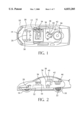
- FIG. 1 is a top plan exploded view of the toy car of the present invention.
- FIG. 2 is a side cross-section view of FIG. 1.
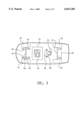
- FIG. 3 is a detailed phantom view of the chassis of the car of the present invention.
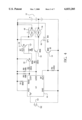
- FIG. 4 is a schematic of an example of electrical circuit useful in the present invention.
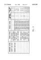
- FIG. 5 is a sample timing sequence for controlling a toy car with effects.
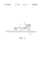
- FIG. 6 is a detailed view of one switching mechanism useful in the present invention.
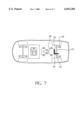
- FIG. 7 is an alternate embodiment of the present invention with a second electric motor connected to wheels forming a propulsion mechanism.
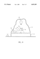
- FIG. 8 is an alternate embodiment of the invention in the form of a board game with a vibrating volcano at its center, where the volcano simulates eruption through vibration, sound and light.
- the toy vehicle 10 comprises a chassis 12 to which a car body 14 is mounted.
- chassis 12 and car body 14 are fabricated of light weight plastic such as ABS or other similar flexible semi-rigid materials which may be inexpensively and easily molded by conventional fabrication techniques.
- the vehicle 10 further includes a pair of front wheels 16 and a pair of rear wheels 18 mounted to chassis 12 via a front axle 20 and rear axle 22 connected to the chassis 12 through axle mounts, which in the present invention are merely slots in the chassis.
- the vehicle has its own propulsion mechanism, such as an electric motor 48 connected to the vehicle's rear wheels 18 (propulsion device) through a set of gears 50 and the rear wheel axles 22.
- axles 20, 22 and wheels 16,18 rotate freely within axle mounts on chassis 12. Additional support is provided to the axles 20,22 by front shock absorbers 24 and rear shock absorbers 26.
- improved vibrations may be achieved by mounting the axles 20, 22 to the chassis through spring type shock absorbers or other mechanical damping mechanism known to those skilled in the art. Spring isolation also increases the vertical vibration of the toy and will dampen the lateral vibration, thus increasing the toy's realism.
- the propulsion device could be continuous track (e.g. toy bull dozer), propeller (e.g. toy airplane) or paddle (e.g. toy boat).
- continuous track e.g. toy bull dozer
- propeller e.g. toy airplane
- paddle e.g. toy boat
- the front shock absorbers 24 also act as an electro-mechanical switch. When the front of the toy car is depressed the front shock absorbers 24 momentarily come into contact with metal plates 30 that are connected by electric wires to a electric power supply 32 and electric circuit 34 mounted in the chassis 12. The momentary closure of the switch 24, 30 activates the electric circuit 34 which then controls the toy through one or more programmed sequences of events.
- FIG. 6 demonstrates how the metal front shock absorbers 24, front axle 20 and metal contact plates 30 act as a switch.
- the body of the vehicle 14 When the body of the vehicle 14 is pressed down it causes the chassis 12 to lower along with the front shock absorbers 24 and the contact plates 30. However, the front axle 20 does not move because its height is fixed by the radius of the front wheels 16. As the front shock absorber 24 and the contact plates 30 lower, the front shock absorbers 24 are pressed by the front axle 20 against the contact plates 30, thus closing the switch. As soon as the vehicle body 14 is released the front shock absorbers 24 and the contact plates 30 lift and separate and the circuit is opened.
- the switch is activated by the insertion or removal of a gasoline nozzle. It will be obvious to those skilled in the art that other switch mechanisms, including push buttons, motion detectors, remote controls, or touch sensors could be used to accomplish the same task.
- the electric circuit 34 connects the power supply 32 to an electro-mechanical vibration generator mounted either to the chassis 12 or the toy body 14, causing the car 10 to vibrate.
- the vibration generator is an electric motor 36 with the shaft 38 of the motor 36 connected to the narrow end of a plastic wedge shaped rigid arm 40 that has two relatively heavy weights 42 attached on the wide end farthest from the motor shaft 38. With the motor 36 running, the weights 42 spin around the shaft 38 generating angular momentum. The angular momentum generated by the spinning masses 42 is transferred through the arm 40, shaft 38 and motor 36 to the chassis 12 which vibrates relative to the axles 20, 22 and wheels 16, 18.
- the motor 36 is mounted so that its shaft 38 is perpendicular to the plane encompassing the bottom of the chassis 12, thus causing the motor 36 to spin in a plane that is parallel with the plane of the chassis 12.
- the motor 36 could be mounted in other orientations in order to achieve different types of vibrations. While the present mechanism for causing vibrations is particularly rugged and cost efficient, many other types of electro-mechanical devices can be used to generate vibrations such as rockers or pistons.
- the electric circuit 34 provides power to a sound source, an electric speaker 46, mounted to the car body 14 or chassis 12. Together, the electric circuit 34 and speaker 46 generate a loud sound that simulates the sound of a race car accelerating its engine while its transmission is in the neutral position (i.e. "revving" its engine).
- FIG. 4 describes and electric circuit 34 of the type that can be used to accomplish the invention.
- the circuit is capable of operating a vibrating toy car, shown in FIG. 7, with sound and propulsion.
- the switching mechanism 52 is an internal push button that is depressed by inserting a toy gas can nozzle into the toy car's gas tank. This begins a timed sequence programmed into the integrated circuit 44 as shown in FIG. 5.
- the integrated circuit 44 is a programmable device capable of controlling timed events and generating analog signals to produce sound. During the initial sequence the car generates the sounds of a race car fueling.
- the sound signal is stored and synthesized by the integrated circuit 44 and amplified through a transistor 54 using electrical power supplied from the power supply 32, in this embodiment, consisting of three batteries.
- the amplified sound signal drives a speaker 46 which converts the electrical signal into an audible signal.
- the switch 52 is released and a new sequence of events begins.
- the integrated circuit generates an "on" signal for the vibration motor 36.
- This signal turns the vibration motor drive transistor 56 on, which in turn allows current from the power supply 32 to flow through the vibration motor 36 causing it to spin.
- the integrated circuit 44 While the vibration motor 36 is spinning, the integrated circuit 44 generates a series of sounds consisting of engine ignition sound followed by idling sounds. At this point, the integrated circuit 44 turns of the vibration motor 36 and at the same time generates a "peel out” sound. When the "peel out” sound ends the integrated circuit 44 generates an "on” signal for the propulsion motor 48.
- a two staged set of transistors 58 is used to amplify the on signal from the integrated circuit and drive the propulsion.
- the propulsion motor 48 turns the rear wheels 18 through a set of gears 50 causing the entire toy car 10 to roll forward.
- the integrated circuit 44 continues to control the toy through a similar series of vibration, sound, and propulsion as further described in FIG. 5.
- the toy vehicle disclosed has a plurality of sequences of events each consisting of two or more effects: ignition, peel out, racing, driving and braking. It will be obvious to those skilled in the art that the integrated circuit 44 can be programmed to accomplish, with the disclosed or similar circuitry, any desired sequence of events. These special effects may include any desired sounds, lights and propulsion (forward, reverse, circular, zig-zag), and vibration, in any sequence, serially or in combination.
- the electric circuit 34 also controls a set of lights mounted on the outside of the car body 14 causing the lights to turn on, or to flash on and off, in synchronization with the sound, propulsion and vibrations.
- the circuitry for a lighting circuit would be similar to the disclosed circuitry and is obvious to those skilled in the art.
- FIG. 8 shows the toy including a vibration generator 36, 40, 42, sound source 46 and light source 60.
- the chassis in the toy vehicle can be any platform 12, and similarly the body 14 can take any shape, such as a mountain or a building.
Abstract
Description
Claims (24)
Priority Applications (1)
| Application Number | Priority Date | Filing Date | Title |
|---|---|---|---|
| US09/020,325 US6033285A (en) | 1998-02-06 | 1998-02-06 | Vibrating toy car with special effects |
Applications Claiming Priority (1)
| Application Number | Priority Date | Filing Date | Title |
|---|---|---|---|
| US09/020,325 US6033285A (en) | 1998-02-06 | 1998-02-06 | Vibrating toy car with special effects |
Publications (1)
| Publication Number | Publication Date |
|---|---|
| US6033285A true US6033285A (en) | 2000-03-07 |
Family
ID=21797989
Family Applications (1)
| Application Number | Title | Priority Date | Filing Date |
|---|---|---|---|
| US09/020,325 Expired - Fee Related US6033285A (en) | 1998-02-06 | 1998-02-06 | Vibrating toy car with special effects |
Country Status (1)
| Country | Link |
|---|---|
| US (1) | US6033285A (en) |
Cited By (27)
| Publication number | Priority date | Publication date | Assignee | Title |
|---|---|---|---|---|
| US6179331B1 (en) * | 1999-02-05 | 2001-01-30 | Mattel, Inc. | Children's ride-on vehicle having a vibrating engine model |
| US6527619B1 (en) * | 2001-10-31 | 2003-03-04 | Mattel, Inc. | Projectile firing toy vehicle |
| US6609943B1 (en) * | 2002-02-05 | 2003-08-26 | Thinking Technology, Inc. | Electronic talking toy and doll combination |
| US6684556B1 (en) * | 2000-06-07 | 2004-02-03 | David B. Arbuckle | Remotely controlled vibrating fishing bait |
| US20040082266A1 (en) * | 1999-07-10 | 2004-04-29 | Ghaly Nabil N. | Interactive paly device and method |
| US20040092208A1 (en) * | 2002-11-01 | 2004-05-13 | Weiss Stephen N. | Remotely controlled toy vehicles with light(s) |
| US6755716B2 (en) | 2002-11-01 | 2004-06-29 | Mattel, Inc. | Projectile shooting toy |
| US6765356B1 (en) * | 1998-11-04 | 2004-07-20 | Lionel L.L.C. | Control and motor arrangement for use in model train |
| WO2005092462A1 (en) * | 2004-03-24 | 2005-10-06 | Genie Toys Plc | Toy vehicle |
| US20060009118A1 (en) * | 2004-05-28 | 2006-01-12 | Mattel, Inc. | Toy vehicle having rotatable light display |
| GB2410448B (en) * | 2002-11-01 | 2006-03-15 | Mattel Inc | Improved remotely controlled toy vehicles with light(s) |
| US20060099882A1 (en) * | 2004-11-08 | 2006-05-11 | Go Products, Inc. | Apparatus, method, and computer program product for toy vehicle |
| WO2006116408A2 (en) * | 2005-04-25 | 2006-11-02 | Joseph Sladky | Amusement device for cell phone |
| US20080132143A1 (en) * | 2005-01-14 | 2008-06-05 | Nikko Co., Ltd. | Reality Generating Device |
| US20080254707A1 (en) * | 2007-04-16 | 2008-10-16 | Retail Entertainment Concepts, Llc | Modular toy vehicle |
| US20080262980A1 (en) * | 2007-04-19 | 2008-10-23 | Ridemakerz, Llc | System and method for assembly of modular toy vehicle |
| US20080263454A1 (en) * | 2007-04-17 | 2008-10-23 | Ridemakerz, Llc | Method of providing a consumer profile accessible by an on-line interface and related to retail purchase of custom personalized toys |
| US20090075557A1 (en) * | 2007-09-13 | 2009-03-19 | Martin Arriola | Toy Illumination with Music |
| US20090156088A1 (en) * | 2005-09-09 | 2009-06-18 | Nikko Co., Ltd. | Ambience creation device, traveling toy, ambience creation method, and ambience creation program |
| US20090284206A1 (en) * | 2008-05-17 | 2009-11-19 | Diehl Ako Stiftung & Co. Kg | Motor controller for controlling an electric motor |
| US20090311941A1 (en) * | 2005-06-18 | 2009-12-17 | Jkid Limited | Portable Device |
| US20100048096A1 (en) * | 2006-01-13 | 2010-02-25 | Marc Lorelli | Simulated degradation features for remotely controlled vehicles |
| US20100062680A1 (en) * | 2008-06-25 | 2010-03-11 | Brandon Giraldez | Touch sensitive toy system |
| US20130072085A1 (en) * | 2010-05-31 | 2013-03-21 | Tomy Company ,Ltd. | Toy vehicle |
| US20140134917A1 (en) * | 2012-11-09 | 2014-05-15 | Bright Kingdom Development Ltd. | Toy with multiple light emitting diodes |
| US8764511B2 (en) | 2011-04-29 | 2014-07-01 | Mattel, Inc. | Toy vehicle |
| US10272350B2 (en) | 2017-06-14 | 2019-04-30 | Dynacraft Bsc, Inc. | Pulsating imitation speaker |
Citations (20)
| Publication number | Priority date | Publication date | Assignee | Title |
|---|---|---|---|---|
| US2832177A (en) * | 1954-12-16 | 1958-04-29 | Mueller Heinrich | Toy vehicle set |
| US3187462A (en) * | 1962-11-15 | 1965-06-08 | Ideal Toy Corp | Electrically propelled and steered toy vehicle |
| US3939605A (en) * | 1972-03-15 | 1976-02-24 | John Allen | Control of accessories for toy or model vehicles |
| US3953027A (en) * | 1975-02-12 | 1976-04-27 | Marvin Glass & Associates | Card matching apparatus including dispenser |
| US4083143A (en) * | 1972-03-15 | 1978-04-11 | John Allen | Control arrangement for toy and model vehicles |
| US4219957A (en) * | 1978-05-31 | 1980-09-02 | Takao Kakuta | Traveling toy |
| US4465949A (en) * | 1983-08-22 | 1984-08-14 | Knauff Robert J | Electromechanical frequency generator-modulator kinetic storage device |
| US4488375A (en) * | 1981-09-29 | 1984-12-18 | Hang Tjuk Industrial Col Ltd. | Toy vehicle with pivotable body |
| US4575357A (en) * | 1982-05-21 | 1986-03-11 | Flexibox Limited | Flexible couplings |
| US4580994A (en) * | 1983-12-15 | 1986-04-08 | Marvin Glass & Associates | Toy vehicle |
| US5088949A (en) * | 1991-01-11 | 1992-02-18 | Virgil Atkinson | Oscillation-driven vehicle |
| US5173072A (en) * | 1990-08-23 | 1992-12-22 | Tomy Company, Ltd. | Travelling toy vehicle with simulated startup vibration |
| US5195920A (en) * | 1989-02-16 | 1993-03-23 | Collier Harry B | Radio controlled model vehicle having coordinated sound effects system |
| US5203559A (en) * | 1992-02-07 | 1993-04-20 | Goldfarb Adolph E | Bowling apparatus having spring driven wind-up striker |
| US5334075A (en) * | 1991-08-23 | 1994-08-02 | Tomy Company, Ltd. | Remote control car steered upon motor reversal |
| US5482494A (en) * | 1993-05-26 | 1996-01-09 | Nikko Co., Ltd. | Toy vehicle having rolling oscillatory motion |
| US5482493A (en) * | 1994-02-22 | 1996-01-09 | Rapisarda; Carmen C. | Toys with a battery powered light emitting diode lighted by movement |
| US5713783A (en) * | 1996-02-14 | 1998-02-03 | Szoke; Anthony A. | Remote controlled toy crash vehicle apparatus |
| US5720646A (en) * | 1995-07-28 | 1998-02-24 | Shannon; Suel G. | Vehicle for use with games or demonstrative tools |
| US5791965A (en) * | 1995-06-07 | 1998-08-11 | Great American Fun Corp. | Light emitting apparatus for stuffed toys and the like |
-
1998
- 1998-02-06 US US09/020,325 patent/US6033285A/en not_active Expired - Fee Related
Patent Citations (20)
| Publication number | Priority date | Publication date | Assignee | Title |
|---|---|---|---|---|
| US2832177A (en) * | 1954-12-16 | 1958-04-29 | Mueller Heinrich | Toy vehicle set |
| US3187462A (en) * | 1962-11-15 | 1965-06-08 | Ideal Toy Corp | Electrically propelled and steered toy vehicle |
| US3939605A (en) * | 1972-03-15 | 1976-02-24 | John Allen | Control of accessories for toy or model vehicles |
| US4083143A (en) * | 1972-03-15 | 1978-04-11 | John Allen | Control arrangement for toy and model vehicles |
| US3953027A (en) * | 1975-02-12 | 1976-04-27 | Marvin Glass & Associates | Card matching apparatus including dispenser |
| US4219957A (en) * | 1978-05-31 | 1980-09-02 | Takao Kakuta | Traveling toy |
| US4488375A (en) * | 1981-09-29 | 1984-12-18 | Hang Tjuk Industrial Col Ltd. | Toy vehicle with pivotable body |
| US4575357A (en) * | 1982-05-21 | 1986-03-11 | Flexibox Limited | Flexible couplings |
| US4465949A (en) * | 1983-08-22 | 1984-08-14 | Knauff Robert J | Electromechanical frequency generator-modulator kinetic storage device |
| US4580994A (en) * | 1983-12-15 | 1986-04-08 | Marvin Glass & Associates | Toy vehicle |
| US5195920A (en) * | 1989-02-16 | 1993-03-23 | Collier Harry B | Radio controlled model vehicle having coordinated sound effects system |
| US5173072A (en) * | 1990-08-23 | 1992-12-22 | Tomy Company, Ltd. | Travelling toy vehicle with simulated startup vibration |
| US5088949A (en) * | 1991-01-11 | 1992-02-18 | Virgil Atkinson | Oscillation-driven vehicle |
| US5334075A (en) * | 1991-08-23 | 1994-08-02 | Tomy Company, Ltd. | Remote control car steered upon motor reversal |
| US5203559A (en) * | 1992-02-07 | 1993-04-20 | Goldfarb Adolph E | Bowling apparatus having spring driven wind-up striker |
| US5482494A (en) * | 1993-05-26 | 1996-01-09 | Nikko Co., Ltd. | Toy vehicle having rolling oscillatory motion |
| US5482493A (en) * | 1994-02-22 | 1996-01-09 | Rapisarda; Carmen C. | Toys with a battery powered light emitting diode lighted by movement |
| US5791965A (en) * | 1995-06-07 | 1998-08-11 | Great American Fun Corp. | Light emitting apparatus for stuffed toys and the like |
| US5720646A (en) * | 1995-07-28 | 1998-02-24 | Shannon; Suel G. | Vehicle for use with games or demonstrative tools |
| US5713783A (en) * | 1996-02-14 | 1998-02-03 | Szoke; Anthony A. | Remote controlled toy crash vehicle apparatus |
Non-Patent Citations (1)
| Title |
|---|
| Rear and bottom box panels of Dodge Viper GTS Toy Car by Buddy L, Inc. * |
Cited By (49)
| Publication number | Priority date | Publication date | Assignee | Title |
|---|---|---|---|---|
| US6765356B1 (en) * | 1998-11-04 | 2004-07-20 | Lionel L.L.C. | Control and motor arrangement for use in model train |
| US7211976B2 (en) | 1998-11-04 | 2007-05-01 | Lionel L.L.C. | Control and motor arrangement for use in model train |
| US20070285043A1 (en) * | 1998-11-04 | 2007-12-13 | Denen Dennis J | Control and motor arrangement for use in model train |
| US7656110B2 (en) | 1998-11-04 | 2010-02-02 | Lionel L.L.C. | Control and motor arrangement for use in model train |
| US20050023999A1 (en) * | 1998-11-04 | 2005-02-03 | Denen Dennis J. | Control and motor arrangement for use in model train |
| US6179331B1 (en) * | 1999-02-05 | 2001-01-30 | Mattel, Inc. | Children's ride-on vehicle having a vibrating engine model |
| US7018265B2 (en) * | 1999-07-10 | 2006-03-28 | Ghaly Nabil N | Interactive play device and method |
| US20040082266A1 (en) * | 1999-07-10 | 2004-04-29 | Ghaly Nabil N. | Interactive paly device and method |
| US6684556B1 (en) * | 2000-06-07 | 2004-02-03 | David B. Arbuckle | Remotely controlled vibrating fishing bait |
| EP1441821A4 (en) * | 2001-10-31 | 2004-12-29 | Mattel Inc | Projectile firing toy vehicle |
| EP1441821A1 (en) * | 2001-10-31 | 2004-08-04 | Mattel, Inc. | Projectile firing toy vehicle |
| WO2003045521A1 (en) * | 2001-10-31 | 2003-06-05 | Mattel, Inc. | Projectile firing toy vehicle |
| US6527619B1 (en) * | 2001-10-31 | 2003-03-04 | Mattel, Inc. | Projectile firing toy vehicle |
| US6609943B1 (en) * | 2002-02-05 | 2003-08-26 | Thinking Technology, Inc. | Electronic talking toy and doll combination |
| US6755716B2 (en) | 2002-11-01 | 2004-06-29 | Mattel, Inc. | Projectile shooting toy |
| US20040092208A1 (en) * | 2002-11-01 | 2004-05-13 | Weiss Stephen N. | Remotely controlled toy vehicles with light(s) |
| GB2410448B (en) * | 2002-11-01 | 2006-03-15 | Mattel Inc | Improved remotely controlled toy vehicles with light(s) |
| US7234992B2 (en) | 2002-11-01 | 2007-06-26 | Mattel, Inc. | Remotely controlled toy vehicles with light(s) |
| WO2005092462A1 (en) * | 2004-03-24 | 2005-10-06 | Genie Toys Plc | Toy vehicle |
| GB2428985A (en) * | 2004-03-24 | 2007-02-14 | Genie Toys Plc | Toy vehicle |
| US20070190895A1 (en) * | 2004-03-24 | 2007-08-16 | Genie Toys Plc, | Toy vehicle |
| US7367863B2 (en) | 2004-05-28 | 2008-05-06 | Mattel, Inc. | Toy vehicle having rotatable light display |
| US20060009118A1 (en) * | 2004-05-28 | 2006-01-12 | Mattel, Inc. | Toy vehicle having rotatable light display |
| US7988519B2 (en) * | 2004-11-08 | 2011-08-02 | Go Products, Inc. | Apparatus, method, and computer program product for toy vehicle |
| US20060099882A1 (en) * | 2004-11-08 | 2006-05-11 | Go Products, Inc. | Apparatus, method, and computer program product for toy vehicle |
| US20080132143A1 (en) * | 2005-01-14 | 2008-06-05 | Nikko Co., Ltd. | Reality Generating Device |
| WO2006116408A3 (en) * | 2005-04-25 | 2007-03-08 | Joseph Sladky | Amusement device for cell phone |
| WO2006116408A2 (en) * | 2005-04-25 | 2006-11-02 | Joseph Sladky | Amusement device for cell phone |
| US7927170B2 (en) * | 2005-06-18 | 2011-04-19 | Jkid Limited | Portable device |
| US20090311941A1 (en) * | 2005-06-18 | 2009-12-17 | Jkid Limited | Portable Device |
| US20090156088A1 (en) * | 2005-09-09 | 2009-06-18 | Nikko Co., Ltd. | Ambience creation device, traveling toy, ambience creation method, and ambience creation program |
| US8033888B2 (en) * | 2006-01-13 | 2011-10-11 | Marc Lorelli | Simulated degradation features for remotely controlled vehicles |
| US20100048096A1 (en) * | 2006-01-13 | 2010-02-25 | Marc Lorelli | Simulated degradation features for remotely controlled vehicles |
| US7896724B2 (en) | 2007-04-16 | 2011-03-01 | Ridemakerz, LLP | Modular toy vehicle |
| US8435094B2 (en) | 2007-04-16 | 2013-05-07 | Ridemakerz, Llc | Modular toy vehicle |
| US7568962B2 (en) | 2007-04-16 | 2009-08-04 | Ridemakerz, Llc | Modular toy vehicle |
| US20110143630A1 (en) * | 2007-04-16 | 2011-06-16 | Ridemakerz, Llc | Modular toy vehicle |
| US20080254707A1 (en) * | 2007-04-16 | 2008-10-16 | Retail Entertainment Concepts, Llc | Modular toy vehicle |
| US20080263454A1 (en) * | 2007-04-17 | 2008-10-23 | Ridemakerz, Llc | Method of providing a consumer profile accessible by an on-line interface and related to retail purchase of custom personalized toys |
| US8548819B2 (en) | 2007-04-17 | 2013-10-01 | Ridemakerz, Llc | Method of providing a consumer profile accessible by an on-line interface and related to retail purchase of custom personalized toys |
| US20080262980A1 (en) * | 2007-04-19 | 2008-10-23 | Ridemakerz, Llc | System and method for assembly of modular toy vehicle |
| US20090075557A1 (en) * | 2007-09-13 | 2009-03-19 | Martin Arriola | Toy Illumination with Music |
| US8179060B2 (en) * | 2008-05-17 | 2012-05-15 | Diehl Ako Stiftung & Co. Kg | Motor controller for controlling an electric motor |
| US20090284206A1 (en) * | 2008-05-17 | 2009-11-19 | Diehl Ako Stiftung & Co. Kg | Motor controller for controlling an electric motor |
| US20100062680A1 (en) * | 2008-06-25 | 2010-03-11 | Brandon Giraldez | Touch sensitive toy system |
| US20130072085A1 (en) * | 2010-05-31 | 2013-03-21 | Tomy Company ,Ltd. | Toy vehicle |
| US8764511B2 (en) | 2011-04-29 | 2014-07-01 | Mattel, Inc. | Toy vehicle |
| US20140134917A1 (en) * | 2012-11-09 | 2014-05-15 | Bright Kingdom Development Ltd. | Toy with multiple light emitting diodes |
| US10272350B2 (en) | 2017-06-14 | 2019-04-30 | Dynacraft Bsc, Inc. | Pulsating imitation speaker |
Similar Documents
| Publication | Publication Date | Title |
|---|---|---|
| US6033285A (en) | Vibrating toy car with special effects | |
| US6089951A (en) | Toy vehicle and trackset having lap-counting feature | |
| JP3429293B2 (en) | Wireless control bicycle | |
| US4389811A (en) | Bird action toy | |
| US4463515A (en) | Self-contained and self-propelled toy vehicle | |
| US5273478A (en) | Toy vehicle having motor sound | |
| JP2801882B2 (en) | Vehicle gaming machine | |
| WO2001056675A1 (en) | Remotely controlled skateboard having motion-responsive doll riding thereon | |
| JP2839346B2 (en) | Running toys | |
| AU755648B2 (en) | Children's ride-on vehicle having a vibrating engine model | |
| US6579145B1 (en) | Toy comprising interconnected figures having directionally selectable spring-loaded propulsion mechanisms | |
| US6699098B1 (en) | Animated musical alligator | |
| JP2009297454A (en) | Traveling toy | |
| JP3265099B2 (en) | Car for toys | |
| US5660575A (en) | Toys capable of being animated by depressing | |
| US4140325A (en) | Toy vehicle | |
| US9474987B1 (en) | Multiple sonic motion devices | |
| JPS6348311Y2 (en) | ||
| CN218306141U (en) | Toy walking tractor | |
| US6612897B2 (en) | Musical toy with a motor driven display | |
| JPH0327679Y2 (en) | ||
| US4680020A (en) | Toy vehicle having simulated engine noise | |
| JP3217559U (en) | Traveling toy | |
| JP3223256U (en) | Traveling toy | |
| JPH11188186A (en) | Rolling toy |
Legal Events
| Date | Code | Title | Description |
|---|---|---|---|
| AS | Assignment |
Owner name: TOY BIZ, INC., NEW YORK Free format text: ASSIGNMENT OF ASSIGNORS INTEREST;ASSIGNORS:FINE, ALAN;NIELSEN, PAUL;REEL/FRAME:009231/0342 Effective date: 19980601 |
|
| AS | Assignment |
Owner name: TOY BIZ, INC., NEW YORK Free format text: ASSIGNMENT OF ASSIGNORS INTEREST;ASSIGNORS:FINE, ALAN;NIELSEN, PAUL;REEL/FRAME:009418/0306 Effective date: 19980601 |
|
| AS | Assignment |
Owner name: UBS AG, STAMFORD BRANCH, AS COLLATERAL AGENT, CONN Free format text: SECURITY AGREEMENT;ASSIGNOR:TOY BIZ, INC.;REEL/FRAME:009614/0638 Effective date: 19980930 |
|
| AS | Assignment |
Owner name: MARVEL ENTERPRISES, INC., NEW YORK Free format text: CHANGE OF NAME;ASSIGNOR:TOY BIZ, INC.;REEL/FRAME:010495/0846 Effective date: 19981215 |
|
| AS | Assignment |
Owner name: MARVEL ENTERPRISES, INC. (F/K/A TOY BIZ, INC.), NE Free format text: RELEASE OF SECURITY INTEREST;ASSIGNOR:UBS AG, STAMFORD BRANCH;REEL/FRAME:012916/0635 Effective date: 19990225 |
|
| REMI | Maintenance fee reminder mailed | ||
| LAPS | Lapse for failure to pay maintenance fees | ||
| FP | Lapsed due to failure to pay maintenance fee |
Effective date: 20040307 |
|
| STCH | Information on status: patent discontinuation |
Free format text: PATENT EXPIRED DUE TO NONPAYMENT OF MAINTENANCE FEES UNDER 37 CFR 1.362 |