US6037555A - Rotary contact circuit breaker venting arrangement including current transformer - Google Patents
Rotary contact circuit breaker venting arrangement including current transformer Download PDFInfo
- Publication number
- US6037555A US6037555A US09/225,988 US22598899A US6037555A US 6037555 A US6037555 A US 6037555A US 22598899 A US22598899 A US 22598899A US 6037555 A US6037555 A US 6037555A
- Authority
- US
- United States
- Prior art keywords
- cassette
- breaker
- circuit breaker
- current transformer
- vent
- Prior art date
- Legal status (The legal status is an assumption and is not a legal conclusion. Google has not performed a legal analysis and makes no representation as to the accuracy of the status listed.)
- Expired - Lifetime
Links
Images


Classifications
-
- H—ELECTRICITY
- H01—ELECTRIC ELEMENTS
- H01H—ELECTRIC SWITCHES; RELAYS; SELECTORS; EMERGENCY PROTECTIVE DEVICES
- H01H1/00—Contacts
- H01H1/12—Contacts characterised by the manner in which co-operating contacts engage
- H01H1/14—Contacts characterised by the manner in which co-operating contacts engage by abutting
- H01H1/20—Bridging contacts
- H01H1/2041—Rotating bridge
- H01H1/2058—Rotating bridge being assembled in a cassette, which can be placed as a complete unit into a circuit breaker
-
- H—ELECTRICITY
- H01—ELECTRIC ELEMENTS
- H01H—ELECTRIC SWITCHES; RELAYS; SELECTORS; EMERGENCY PROTECTIVE DEVICES
- H01H9/00—Details of switching devices, not covered by groups H01H1/00 - H01H7/00
- H01H9/30—Means for extinguishing or preventing arc between current-carrying parts
- H01H9/34—Stationary parts for restricting or subdividing the arc, e.g. barrier plate
- H01H9/342—Venting arrangements for arc chutes
-
- H—ELECTRICITY
- H01—ELECTRIC ELEMENTS
- H01H—ELECTRIC SWITCHES; RELAYS; SELECTORS; EMERGENCY PROTECTIVE DEVICES
- H01H73/00—Protective overload circuit-breaking switches in which excess current opens the contacts by automatic release of mechanical energy stored by previous operation of a hand reset mechanism
- H01H73/02—Details
- H01H73/04—Contacts
- H01H73/045—Bridging contacts
Definitions
- the invention relates to rotary contact circuit breakers. More particularly, the invention relates to the exhausting of gasses generated within the circuit breaker by a short circuit interruption.
- the separation of the contacts due to a short circuit causes an electrical arc to form between the separating contacts.
- the arc causes the formation of relatively high pressure gasses as well as ionization of air molecules within the arc chamber of the circuit breaker.
- the gasses are hot and deleterious to electrical components.
- the ionized gasses are highly volatile and ignitable upon intermixing with ionized gasses from different electrical phases. The gasses, therefore, must be kept separate until the ionization has dissipated and temperature of the gasses has moderated.
- An exhaust port is conventionally employed to vent such gasses in a rotary contact circuit breaker, each pole or phase employs two sets of contacts, two contacts of which rotate about a common axis generally perpendicular to the current path from the line side to the load side of the circuit breaker.
- Each contact set in such an arrangement requires an exhaust port to expel gasses.
- One of the exhaust ports will be on the line side and one of the exhaust ports will be on the load side of the breaker.
- the exhaust port on the line side is located near the top of the beaker. Since gasses naturally flow in the direction of this port on the line side of the breaker, the port is effective.
- the gasses formed consequent to a short circuit naturally migrate toward the lower corner of the breaker. Thus, it is axiomatic that an exhaust port is located at this corner providing there is sufficient room to exhaust gasses from this port.
- a venting arrangement is created by providing cooperating cavities (when assembled) with a base, midcover, cassettes, current transformer (or thermomag) housing and spacers which provide a series of channels for routing ionized gasses independently of one another to an appropriate outlet.
- the venting arrangement of the invention conveys the gasses without damaging other components of the circuit breaker. Moreover, the arrangement maximizes venting volume and allows for minimization of the overall size of the circuit breaker.
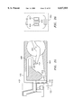
- FIG. 1 is a perspective view of one embodiment of the circuit breaker of the invention
- FIG. 2 is an exploded perspective view of the circuit breaker of FIG. 1 illustrating components in an assembled condition
- FIG. 3 is an exploded perspective view of a cassette of the invention
- FIG. 4 is a partial cross section assembled view of the components in FIG. 5 taken along section line 4--4;
- FIG. 5 is a partial cross section view of a cassette of the invention.
- FIG. 6 is an exploded perspective view of a group of three current transformers with housing, vent channels and end vent channels illustrated;
- FIG. 7 is semi-exploded perspective view of a current transformer within its housing and a vent channel
- FIG. 8 is semi-exploded perspective view of a current transformer as in FIG. 7 but with a second vent channel added on the housing;
- FIG. 9 is an exploded perspective view of a cassette assembly, current transformer assembly and load straps of the invention.
- FIG. 10 is a side view of a vent channel with attached components
- FIG. 11 is a cross section view of the components of FIG. 10 taken along section line 11--11;
- FIG. 12 is a cross section view of the components of FIG. 10 taken along section line 12--12;
- FIG. 13 is an enlarged view of the load end of the embodiment of FIG. 1 wherein mechanical interaction of several parts is illustrated;
- FIG. 14 is a load side elevation view of the first circuit breaker embodiment of the invention.
- FIG. 15 is a partially broken away top plan view of the first embodiment of the invention.
- FIG. 16 is a partial cross section illustration of the circuit breaker of FIG. 15;
- FIG. 17 is a perspective view of an alternative embodiment of the invention that employs the cassette as described above and a thermomag trip unit in place of the current transformer of the previous embodiment;
- FIG. 18 is an exploded perspective view of the housing portions of the trip unit illustrated in FIG. 17;
- FIG. 19 is a cross section view of the trip unit taken along section line 19--19 in FIG. 17;
- FIG. 20 is an exploded perspective view of the thermomag tripper and its housing
- FIG. 21 is a perspective view of another cassette embodiment of the invention.
- FIG. 22 is a cross section view of the cassette of FIG. 21 in a complementary housing
- FIG. 23 is a perspective view of another cassette embodiment of the invention.
- FIG. 24 is a cross section view of the cassette of FIG. 23 in a complementary housing
- FIG. 25 is a schematic cross section of another cassette and current transformer arrangement of the invention.
- FIG. 26 is a cross section view of an embodiment invention taken along section line 26--26 in FIG. 25;
- FIG. 27 is a perspective exploded view of another cassette and CT housing of the invention.
- FIG. 28 is a perspective view of the parts illustrated in FIG. 27 but 90° turned;
- FIG. 29 is an exploded perspective view of this embodiment of the invention with all internal subassemblies shown.
- FIG. 30 is an assembled view of this embodiment.
- FIG. 1 a first embodiment of the invention is illustrated in perspective assembled form.
- the entire device is referred to as 10 herein.
- Exterior features include a base 12 which provides support for and protection to the internal components discussed hereunder.
- Midcover 14 is dimensioned and shaped to reside atop base 12 and as an extension thereof and to cover the internal components. It should be noted that load side vent ports 16 are visible in FIG. 1.
- load side vent ports 16 are visible in FIG. 1.
- Base 12 includes bottom wall 20 and side walls 22 defining an interior cavity adapted to receive and support a plurality of internal electrical components.
- the adaptation in general will include locating tangs and stiffening ribs.
- locating tangs 24 are visible extending upwardly from bottom wall 20 and in line with stiffening ribs 26.
- Ribs 26 preferably include shoulder 28 at a height from bottom 20 equivalent to the extent of location tangs 24 to effectively provide a support surface for the internal electrical components.
- Extending from the line side of the base 12 are line strap spacers 30.
- two spacers 30 are provided at equal intervals between side walls 22 to divide the space between the side walls into three equal segments.
- Each spacer 30 includes a through bore 32 for mounting purposes.
- a groove 34 is also provided in sidewalls 22 to complement through bore 32 and is also for mounting purposes.
- Extending from bottom 20 at the line side edge of base 12 are stub walls 36 which support spacers 30 and protect internal components of circuit breaker 10.
- partitions 40 are complemented by sidewall extensions 44 (are on each side of base 12) which each provide a groove 46 for mounting circuit breaker 10 and similar features to partitions 40 for interconnection with internal components.
- the features of partitions 40 and sidewall extensions 44 that interconnect with internal components and particularly the gas exhaust structures are flange groove 48 which is identical among partitions and sidewall extensions and hollow 50.
- Groove 48 is preferably a ninety degree extended groove that receives a flange in the exhaust structures.
- Hollow 50 is a recess in each partition 40 and sidewall extension 44 to further locate and stabilize the internal structures.
- Midcover 60 fits flush to the outside with sidewalls 22 of base 12 and flush with individual partitions 40, spacers 30 sidewall extensions 44 and sideback extensions 31 with, respectively, partition caps 62, spacer caps 64, sidewall extension caps 66 and sideback extension caps 68.
- Bores 70 are for mounting the circuit breaker 10 to a support (not shown).
- the breaker comprises a plurality of cassette assemblies 80 each connected to one current transformer of a block of current transformers 140.
- the individual cassettes each include a load strap 150 each of which is attached through a current transformer.
- the cassettes 80 and the current transformer block 140 together, in addition to providing the conventional electrical function, also provide gas exhaust pathways for each rotary contact breaker cassette.
- FIG. 3 Considering the individual internal components in greater detail, reference is made to FIG. 3. It should be appreciated that since the invention is specifically directed only to exhaust gas pathway parts of the cassette, only parts relevant to this function are illustrated. It is within the level of skill of one of ordinary skill in the art to understand how to make and use the conventional (not discussed or shown) portions of the circuit breaker cassette.
- the cassette 80 is illustrated in FIG. 3 in an exploded perspective view to provide an understanding of the gas pathways presented at the line side 82 of the cassette, one of skill in the art will appreciate that the gas expansion area 84 is directly above the area where a contact is made (contacts not shown). Vent 86 is easily positioned in a location very conducive to exhausting the gasses.
- the gas expansion area opens from the contact area under contact 92.
- the expansion area provides (see FIG. 5) a generally rectangular area 94 which opens to a trapezoidal area 96 which steps downward from area 94 at step 98.
- Adjacent trapezoidal area 96 is diverter recess 100 including diverter step 102 which is provided to help locate diverter 104 in recess 100.
- diverter recess 100 further includes a slot 106 to receive a top edge of diverter 104.
- diverter 104 will slide laterally into the recess 100 with a top edge 108 of diverter 104 in slot 106 and a toe 110 (see FIGS. 4 and 5) of diverter 104 in contact with diverter step 102 until diverter stop 112 comes into contact with stop recess wall 114. It should be appreciated that all of the features described on what is the left side of the cassette in FIG. 3 are mirrored on the right side of the cassette.
- diverter 104 is less thick at the head 116 and more thick at the toe 110 when viewed relative to seal wall 118. This creates a passage dimension, when combined with cassette 80, that is effective in conveying exhaust gas. Exhaust exits 120 and 122 from cassette 80 are shown in FIG. 4.
- cassette 80 is provided on both sides thereof with gas shutoff 124 which resides in connection recess 126 extending inwardly from sidewall 128 of cassette 80.
- gas shutoff 124 which resides in connection recess 126 extending inwardly from sidewall 128 of cassette 80.
- These features are mirrored in the opposite sidewall of cassette 80 and provide an interlocking arrangement with a mating vent channel in the current transformers.
- the gas shutoff and its mating channel provide the required over surface and through-air clearance required by the UL standard.
- Cassette 80 further provides a vent recess 130 which allows an overlapped attachment to vent structures within the current transformer block 140.
- each cassette 80 is provided with groove 132 for overlapping with the CT housing to provide over surface clearances and notches 134, 136 and 138 for clearance with base.
- Each current transformer (CT) 142 is enclosed in a housing having distinct first and second sides. Housing side 144 is illustrated on the right side of each CT 142 in drawing FIG. 6 and housing side 146 on the left. The housing sides together form an opening 161 for through passage of a contact strap discussed hereunder.
- side 144 has an upper lip 148 which is receivable in housing side 146 in recess 150 and side 146 includes lower lip 149 which conversely to lip 148 is receivable in side 144.
- the lips 148 and 152 (a, b, c, d) assist to reliably attach the two housing sides together and are conventional features. All other internal features of housing sides 144 and 146 are also conventional and do not require discussion. Exterior features of each of the housing sides 144 and 146 however provide significant advantages in accordance with the invention.
- vent structure 180 Externally to each housing side, referring to FIGS. 6 and 7, is a depressed path 152 divided into paths 152a and 152b which join at each end of the paths.
- the paths 152a and 152b are enclosed upon attachment of vent structure 180 one of which is preferably located on each side of assembled housing sides 144 and 146. Housing side 144 and 146 provide location lug 154 and bifurcation lug 156 both of which aid in attachment of vent structure 180.
- depression 152a/152b continues to inlet 158 and outlet 160. Focusing on vent structure 180 (FIG. 7), connector member 182 includes several features adapted to connect the structure 180 to a cassette 80.
- shutoff recess 184 receives gas shutoff 124, wall 190 blocks gas escape from rearwardly of the pathway and tang 186 is received in groove 132.
- Bifurcated pathways 152c and 152d mate with pathways 152a and 152b respectively to form the centrally bifurcated exhaust gas conduit 152 the ends of which are radiused, see 188 at the inlet side of 192 at the outlet side (which culminates at port 16).
- Locating recess 194 communicates with location lug 154 and bifurcation 196 nests with bifurcation lug 156 when the vent structure 180 is attached to CT housing side 144 or 146.
- Vent structure 180 To help seal the pathway 152, upper pathway lip 200 and lower pathway lip 202 are provided on vent structure 180 and rest within the edges of depression 152a and 152b, respectively. Vent structure 180 finally includes base-midcover mating structure 204 which includes flange 206 for reception in groove 48 upon assembly of the device 10. Bore 208 provides for through passage of circuit breaker mounting screws.
- vent structures meant to be employed between two current transformers include the above discussed features on both sides whereas vent structures meant to be used on an end of the CT block 140 have such structures on one side.
- vent structures provide segregated pathways cassette-to-cassette to avoid mixing ionized exhaust gas until the ionization has diminished.
- FIG. 9 a linearly partially exposed perspective view of the operable portions of the device 10 of the invention is illustrated.
- Three cassettes 80 are illustrated for a three pole circuit breaker. These are attachable to current transformer block 140 as described hereinbefore.
- current transformer block 140 Through each CT 142 are openings 161 for cores 210 which are preferably positioned between the two coils of the current transformer to pass the current that generates the magnetic field.
- the cores 210 are bored 212 so that load lugs 240 may be attached with screws 214 through screw holes 218 electrically to load straps 216 by threaded holes 220.
- FIGS. 10-12 further understanding of the arrangement of the invention is provided.
- the figures represent a portion of a cassette attached to a current transformer complete with housing and two vent structures (one on each side of the current transformer housings).
- FIGS. 17-20 a second embodiment of the invention is introduced by illustrating only those portions of the device which differ from the previous embodiment. More specifically, the cassette illustrated above is not shown here as it does not change in this embodiment. Rather only the thermomagnetic tripping unit and housing is illustrated here which provides a venting arrangement of the invention.
- the unifying premise of the invention i.e. exhausting exhaust gasses above the load strap, obtains.
- a front housing 250 having three compartments 252 is mateble with a rear housing 254 also having three compartments 256. Visible in FIG. 18 are compartment partitions 258 which are mirrored in front housing 250 and mate at the parting line between these two housings. This provides separation of gasses flowing from different phase circuits which is beneficial for reasons noted earlier.
- An upper chamber 260a/260b is also shown atop the front and rear housing.
- vent structure 266 functions as does vent structure 180 of the prior embodiment in all respects and therefore does not require separate explanation here.
- upper bimetal housings 270 and lower bimetal housings 272. These housings together house the thermomag trip units of the device. Opening 276 in each upper housing allows portions of the thermomag unit 274 (FIG. 19) to extend through into chamber 266 where a mechanical trip is located.
- a profile 280 is shown which causes a bifurcated channel 282a and 282b to be formed around profile 280.
- Profile 280 preferably contacts either an interior surface of an exterior wall of housing 250 or 254 or a surface of compartment partitions 258 depending upon location. Compartment partitions 258 make contact on both major surfaces with adjacent bimetal housing profiles 280. The surface with which profile 280 makes contact, functions as a wall of the channel 282a or 282b.
- vent opening seals 284 which both properly locate the bimetal housing in the front housing 250 and help prevent gas mixing within front housing 250.
- vent channel seal 286 is provided at the rear of lower bimetal housing 272 and is to be received in vent channel inlet 288.
- Seal 286 includes notch 287 to provide a good overlapped seal to the cassette.
- Inlet 288 receives exhaust gas from the cassette which is not shown in the drawings of this embodiment but will be understood by one of ordinary skill in the art from the drawings in the foregoing embodiment.
- Chamber 260 houses a standard circuit breaker trip unit mechanism 290 (FIG. 19) that does not produce exhaust gasses.
- the trip units described in U.S. Pat. Nos. 5,392,016; 5,381,120; 5,121,092; and 5,146,195 (the entire contents of all of which are incorporated herein by reference) are similar to the type illustrated herein.
- venting of the load side 300 of the cassette 302 is accomplished by providing a scallop 304 having a generally L-shaped configuration which conveys exhaust gasses from the load side to the line side of the cassette.
- the scallop 304 in cassette 302 represents a portion of an exhaust flow channel which can be viewed in section in a completed form in FIG. 22.
- the channel is identified as 308.
- Channel 308 is completed by partition walls 310 from midcover 312 meeting partition walls 314 from base 316. Walls 310 and 312 meet in abutting relationship at 318.
- surface 320 acts as a spacer from partition walls 310, 312 and thus causes the walls not to meet surface 322 which forms the side of scallop 304.
- Scallop 304 extends to the line side 328 of cassette 302 and communicates preferably directly with exhaust opening 324.
- cassette 340 includes vent chimney 342 and overhang 344 on both sides thereof.
- the chimney 342 is in fluid communication with exhaust opening 346 and provides a directly upward path for exhaust gas to travel toward midcover channel 348.
- Overhang 344 is provided to form the floor of the channel 348.
- Base 352 is attached to spacers 354 in any of a number of known ways.
- Midcover 350 preferably includes spacer mates 356 which are received in groove 358 in spacer 354. Spacer mates 356 are thin in cross section to provide a larger midcover channel 348.
- midcover 350 Another feature of midcover 350 is channel separator 360 which preferably rests atop cassette 340 when midcover 350 is assembled with base 352. In the assembled condition, chimney 342 intersects midcover channel 348 at about 90°. Midcover channel 348 leads to an exhaust vent (not shown) at the line side of the cassette.
- the load side exhaust gasses are vented directly through the center of the current transformer.
- the current transformers are of the type described previously herein but preferably provide more space between the coils to allow for the slightly larger agglomeration of parts than simply the load terminal strap as illustrated in FIG. 26.
- a cross section of the rotary break circuit breaker cassette 400 is illustrated schematically with a rotor 402 contacts 404 and 406, load strap 408 and load terminal strap 410 shown. Also shown is an exhaust gas area 414 and a port 416.
- the cassette 400 is generally conventional and it is the current transformer housing and vent channels that provides the inventive venting arrangement.
- Vent channel 418 extends from the port 416 outwardly from cassette 400 and then steeply upward in vent riser 420.
- Vent riser 420 is located on both sides of the cassette so that the vent path will extend around both sides of the load terminal strap 410 in the current transformer 422 so that conduit volumetric capacity is not reduced.
- two individual exit risers 430 extend upwardly and to a first opening in the CT housing (not shown) similar to the foregoing CT housing embodiments.
- riser 420 reaches the mid height of current transformer 422 it hits vent-through-channels 424 and is directed through the coils of a current transformer 422.
- vent-through-channels 424 are closely adjacently placed with load terminal strap 410 in the sensor of the current transformer 422.
- cassette 500 is constructed differently to stagger the cassette load side openings 502 and 504.
- the purpose of stagging these openings is to provide a larger vent channel.
- the vent channel does not need to be split in half, as in the first embodiment, to handle gasses from adjacent cassettes. Rather, since the openings are staggered the gas channels can be full width between adjacent current transformer housings.
- opening 502 will communicate with channel 506 through channel inlet 508.
- extension 510 when CT housing 512 is connected to cassette 500, extends downwardly behind boss 514 of opening 502. Gasses conducted through channel 506 are vented from a vent 520 which can only be viewed in FIG. 28.
- the upper channel 516 is used by an adjacent cassette through an opening 504, reference being made to FIG. 28.
- Arrow 522 points to an opening in CT housing 512 such that channel 516b/516a (when assembled) will receive the gasses emitted from opening 504.
- Channel 506a/506b (assembled) receive the gasses from opening 502. Referring back to the channel of 516a/516b, the exit vent 526 is visible in FIG. 27.
- FIG. 29 an exploded view of the invention with several cassettes 500 side-by-side and CT housings 512 likewise side-by-side from the above discussion and thus figure those of skill in the art will understand the invention.
- FIG. 19 is also important to introduce additional elements necessary to form channels 516a/516b and 506a/506b.
- An electronic trip unit 530 is mounted atop a bank of CT housings 512 and includes rib structures 532 which are nested in the open top of each channel 516a/516b to seal the same.
- the bottom of channel 506a/506b is interior surface 536 of base 540.
Abstract
Description
Claims (12)
Priority Applications (3)
| Application Number | Priority Date | Filing Date | Title |
|---|---|---|---|
| US09/225,988 US6037555A (en) | 1999-01-05 | 1999-01-05 | Rotary contact circuit breaker venting arrangement including current transformer |
| PCT/US1999/031174 WO2000041197A1 (en) | 1999-01-05 | 1999-12-29 | Circuit breaker venting arrangement |
| EP99967745A EP1060490B1 (en) | 1999-01-05 | 1999-12-29 | Circuit breaker venting arrangement |
Applications Claiming Priority (1)
| Application Number | Priority Date | Filing Date | Title |
|---|---|---|---|
| US09/225,988 US6037555A (en) | 1999-01-05 | 1999-01-05 | Rotary contact circuit breaker venting arrangement including current transformer |
Publications (1)
| Publication Number | Publication Date |
|---|---|
| US6037555A true US6037555A (en) | 2000-03-14 |
Family
ID=22847096
Family Applications (1)
| Application Number | Title | Priority Date | Filing Date |
|---|---|---|---|
| US09/225,988 Expired - Lifetime US6037555A (en) | 1999-01-05 | 1999-01-05 | Rotary contact circuit breaker venting arrangement including current transformer |
Country Status (3)
| Country | Link |
|---|---|
| US (1) | US6037555A (en) |
| EP (1) | EP1060490B1 (en) |
| WO (1) | WO2000041197A1 (en) |
Cited By (36)
| Publication number | Priority date | Publication date | Assignee | Title |
|---|---|---|---|---|
| US6188036B1 (en) * | 1999-08-03 | 2001-02-13 | General Electric Company | Bottom vented circuit breaker capable of top down assembly onto equipment |
| US6232570B1 (en) * | 1999-09-16 | 2001-05-15 | General Electric Company | Arcing contact arrangement |
| US6515850B2 (en) * | 2000-07-03 | 2003-02-04 | Schneider Electric Industries Sa | Module combined with an electromagnetic switch appliance |
| US6828885B1 (en) * | 1999-02-04 | 2004-12-07 | Moeller Gmbh | Circuit breaker and method for producing same |
| US20050006350A1 (en) * | 2003-06-04 | 2005-01-13 | Buxton Clifford A. | Air guidance device for cooling a switch part of an electrical switch |
| US20050046528A1 (en) * | 2003-08-29 | 2005-03-03 | Ronald Ciarcia | Interlocking cassettes for dimensional stability |
| US20060152311A1 (en) * | 2002-11-27 | 2006-07-13 | Koji Ohkubo | Electromagnetic contactor |
| US20080074217A1 (en) * | 2006-09-25 | 2008-03-27 | Rockwell Automation Technologies, Inc. | Gas diverter for an electrical switching device |
| US20090002106A1 (en) * | 2007-06-28 | 2009-01-01 | General Electric Company | Circuit breaker apparatus |
| WO2009065706A2 (en) * | 2007-11-21 | 2009-05-28 | Abb S.P.A. | Arc gas exhaust passage for a circuit breaker with a double break contact arrangement |
| US20090277768A1 (en) * | 2008-05-08 | 2009-11-12 | Cooper Technologies Company | Low Oil Trip Assembly for a Fault Interrupter and Load Break Switch |
| WO2009137501A1 (en) | 2008-05-08 | 2009-11-12 | Cooper Technologies Company | Multiple arc chamber assemblies for a fault interrupter and load break switch |
| US20090278635A1 (en) * | 2008-05-08 | 2009-11-12 | Cooper Technologies Company | Fault Interrupter and Load Break Switch |
| US20090279223A1 (en) * | 2008-05-08 | 2009-11-12 | Cooper Technologies Company | Sensor Element for a Fault Interrupter and Load Break Switch |
| US20090279216A1 (en) * | 2008-05-08 | 2009-11-12 | Cooper Technologies Company | Adjustable Rating for a Fault Interrupter and Load Break Switch |
| US20090278636A1 (en) * | 2008-05-08 | 2009-11-12 | Cooper Technologies Company | Indicator for a fault interrupter and load break switch |
| US20100038222A1 (en) * | 2008-08-14 | 2010-02-18 | Cooper Technologies Company | Multi-Deck Transformer Switch |
| US20100038221A1 (en) * | 2008-08-14 | 2010-02-18 | Cooper Technologies Company | Tap Changer Switch |
| US20100097759A1 (en) * | 2008-10-22 | 2010-04-22 | Leviton Manufacturing Co., Inc. | Blast venting for electrical device |
| US7872203B2 (en) | 2008-08-14 | 2011-01-18 | Cooper Technologies Company | Dual voltage switch |
| US20110067988A1 (en) * | 2009-09-18 | 2011-03-24 | Leviton Manufacturing Co., Inc. | Electrical switching component |
| FR2950474A1 (en) * | 2009-09-18 | 2011-03-25 | Schneider Electric Ind Sas | Electrical interrupter device for e.g. tripolar circuit breaker, has chambers connected to channels that discharge onto upstream surface of case, where surface is positioned opposite to downstream surface placed in contact with trigger |
| FR2950473A1 (en) * | 2009-09-18 | 2011-03-25 | Schneider Electric Ind Sas | Unipolar cutoff unit useful in cutoff device for circuit-breaker, comprises rotating contact bridge, pair of fixed contacts connected with bridge, rotating rod having transverse opening, sealing shields, and arc extinction chambers |
| US20110090667A1 (en) * | 2009-10-15 | 2011-04-21 | Leviton Manufacturing Co., Inc. | Electrical component enclosure |
| WO2011033182A3 (en) * | 2009-09-18 | 2011-05-19 | Schneider Electric Industries Sas | Interrupter device having at least one single-pole phase unit comprising a contact bridge and circuit breaker comprising such a device |
| US20120175348A1 (en) * | 2009-09-18 | 2012-07-12 | Schneider Electric IndustriesSAS | Single-Pole Breaking Unit Comprising a Rotary Contact Bridge, Switchgear Device Comprising Such a Unit and Circuit Breaker Comprising Such a Device |
| US8331066B2 (en) | 2008-12-04 | 2012-12-11 | Cooper Technologies Company | Low force low oil trip mechanism |
| US8350168B2 (en) | 2010-06-30 | 2013-01-08 | Schneider Electric USA, Inc. | Quad break modular circuit breaker interrupter |
| CN102891025A (en) * | 2011-07-22 | 2013-01-23 | 西门子公司 | Switching device |
| FR2986659A1 (en) * | 2012-02-02 | 2013-08-09 | Schneider Electric Ind Sas | Unipolar cut off block i.e. ampoule for use in tripolar circuit breaker, has axle fixed at sidewalls of discharge channel to divide rotative valve into non-symmetrical surfaces that are moved to release position to release bypass sections |
| US20140021170A1 (en) * | 2012-07-23 | 2014-01-23 | Lsis Co., Ltd. | Circuit breaker |
| US9478373B2 (en) * | 2013-04-15 | 2016-10-25 | Abb Oy | Electric switch housing |
| US20170062156A1 (en) * | 2014-03-31 | 2017-03-02 | Schaltbau Gmbh | Multipolar power contactor |
| US9953789B2 (en) | 2009-09-18 | 2018-04-24 | Schneider Electric Industries Sas | Single-pole breaking unit comprising a rotary contact bridge, and a switchgear device, and circuit breaker comprising such a unit |
| US10984974B2 (en) * | 2018-12-20 | 2021-04-20 | Schneider Electric USA, Inc. | Line side power, double break, switch neutral electronic circuit breaker |
| US20220367136A1 (en) * | 2021-05-14 | 2022-11-17 | Siemens Industry, Inc. | Molded case circuit breaker with terminal cover having emboss guides for cable box cover alignment and fixing |
Citations (217)
| Publication number | Priority date | Publication date | Assignee | Title |
|---|---|---|---|---|
| US2340682A (en) * | 1942-05-06 | 1944-02-01 | Gen Electric | Electric contact element |
| US2719203A (en) * | 1952-05-02 | 1955-09-27 | Westinghouse Electric Corp | Circuit breakers |
| US2937254A (en) * | 1957-02-05 | 1960-05-17 | Gen Electric | Panelboard unit |
| US3158717A (en) * | 1962-07-18 | 1964-11-24 | Gen Electric | Electric circuit breaker including stop means for limiting movement of a toggle linkage |
| US3162739A (en) * | 1962-06-25 | 1964-12-22 | Gen Electric | Electric circuit breaker with improved trip means |
| US3197582A (en) * | 1962-07-30 | 1965-07-27 | Fed Pacific Electric Co | Enclosed circuit interrupter |
| DE1227978B (en) | 1963-10-04 | 1966-11-03 | Licentia Gmbh | Electrical switchgear, in particular contactor |
| US3307002A (en) * | 1965-02-04 | 1967-02-28 | Texas Instruments Inc | Multipole circuit breaker |
| US3517356A (en) * | 1967-07-24 | 1970-06-23 | Terasaki Denki Sangyo Kk | Circuit interrupter |
| US3631369A (en) * | 1970-04-27 | 1971-12-28 | Ite Imperial Corp | Blowoff means for circuit breaker latch |
| US3803455A (en) * | 1973-01-02 | 1974-04-09 | Gen Electric | Electric circuit breaker static trip unit with thermal override |
| BE819008A (en) | 1973-08-20 | 1974-12-16 | DIFFERENTIAL TRIGGER | |
| US3883781A (en) * | 1973-09-06 | 1975-05-13 | Westinghouse Electric Corp | Remote controlled circuit interrupter |
| US4129762A (en) * | 1976-07-30 | 1978-12-12 | Societe Anonyme Dite: Unelec | Circuit-breaker operating mechanism |
| US4144513A (en) * | 1977-08-18 | 1979-03-13 | Gould Inc. | Anti-rebound latch for current limiting switches |
| US4158119A (en) * | 1977-07-20 | 1979-06-12 | Gould Inc. | Means for breaking welds formed between circuit breaker contacts |
| US4165453A (en) * | 1976-08-09 | 1979-08-21 | Societe Anonyme Dite: Unelec | Switch with device to interlock the switch control if the contacts stick |
| US4166988A (en) * | 1978-04-19 | 1979-09-04 | General Electric Company | Compact three-pole circuit breaker |
| FR2410353B1 (en) | 1977-11-28 | 1980-08-22 | Merlin Gerin | |
| US4220934A (en) * | 1978-10-16 | 1980-09-02 | Westinghouse Electric Corp. | Current limiting circuit breaker with integral magnetic drive device housing and contact arm stop |
| US4255732A (en) * | 1978-10-16 | 1981-03-10 | Westinghouse Electric Corp. | Current limiting circuit breaker |
| US4259651A (en) * | 1978-10-16 | 1981-03-31 | Westinghouse Electric Corp. | Current limiting circuit interrupter with improved operating mechanism |
| US4263492A (en) * | 1979-09-21 | 1981-04-21 | Westinghouse Electric Corp. | Circuit breaker with anti-bounce mechanism |
| US4276527A (en) * | 1978-06-23 | 1981-06-30 | Merlin Gerin | Multipole electrical circuit breaker with improved interchangeable trip units |
| US4297663A (en) * | 1979-10-26 | 1981-10-27 | General Electric Company | Circuit breaker accessories packaged in a standardized molded case |
| US4301342A (en) * | 1980-06-23 | 1981-11-17 | General Electric Company | Circuit breaker condition indicator apparatus |
| US4360852A (en) * | 1981-04-01 | 1982-11-23 | Allis-Chalmers Corporation | Overcurrent and overtemperature protective circuit for power transistor system |
| US4368444A (en) * | 1980-08-29 | 1983-01-11 | Siemens Aktiengesellschaft | Low-voltage protective circuit breaker with locking lever |
| US4375021A (en) * | 1980-01-31 | 1983-02-22 | General Electric Company | Rapid electric-arc extinguishing assembly in circuit-breaking devices such as electric circuit breakers |
| US4375022A (en) * | 1979-03-23 | 1983-02-22 | Alsthom-Unelec | Circuit breaker fitted with a device for indicating a short circuit |
| US4376270A (en) * | 1980-09-15 | 1983-03-08 | Siemens Aktiengesellschaft | Circuit breaker |
| US4383146A (en) * | 1980-03-12 | 1983-05-10 | Merlin Gerin | Four-pole low voltage circuit breaker |
| US4392036A (en) * | 1980-08-29 | 1983-07-05 | Siemens Aktiengesellschaft | Low-voltage protective circuit breaker with a forked locking lever |
| US4393283A (en) * | 1980-04-10 | 1983-07-12 | Hosiden Electronics Co., Ltd. | Jack with plug actuated slide switch |
| US4401872A (en) * | 1981-05-18 | 1983-08-30 | Merlin Gerin | Operating mechanism of a low voltage electric circuit breaker |
| US4409573A (en) * | 1981-04-23 | 1983-10-11 | Siemens-Allis, Inc. | Electromagnetically actuated anti-rebound latch |
| FR2512582B1 (en) | 1981-09-10 | 1983-10-28 | Merlin Gerin | |
| EP0061092B1 (en) | 1981-03-20 | 1983-12-21 | BASF Aktiengesellschaft | Electrophotographic recording material |
| BE897691A (en) | 1982-09-08 | 1984-01-02 | Merlin Gerin | MIXED DIFFERENTIAL AND SHORT-CIRCUIT TRIGGER EQUIPPED WITH A COMMON HOMOPOLAR CURRENT CURRENT TRANSFORMER |
| US4435690A (en) * | 1982-04-26 | 1984-03-06 | Rte Corporation | Primary circuit breaker |
| US4467297A (en) * | 1981-05-07 | 1984-08-21 | Merlin Gerin | Multi-pole circuit breaker with interchangeable magneto-thermal tripping unit |
| US4468645A (en) * | 1981-10-05 | 1984-08-28 | Merlin Gerin | Multipole circuit breaker with removable trip unit |
| EP0117094A1 (en) | 1983-02-18 | 1984-08-29 | Heinemann Electric Company | A circuit breaker comprising parallel connected sections |
| US4470027A (en) * | 1982-07-16 | 1984-09-04 | Eaton Corporation | Molded case circuit breaker with improved high fault current interruption capability |
| US4479143A (en) * | 1980-12-16 | 1984-10-23 | Sharp Kabushiki Kaisha | Color imaging array and color imaging device |
| US4488133A (en) * | 1983-03-28 | 1984-12-11 | Siemens-Allis, Inc. | Contact assembly including spring loaded cam follower overcenter means |
| US4541032A (en) * | 1980-10-21 | 1985-09-10 | B/K Patent Development Company, Inc. | Modular electrical shunts for integrated circuit applications |
| US4546224A (en) * | 1982-10-07 | 1985-10-08 | Sace S.P.A. Costruzioni Elettromeccaniche | Electric switch in which the control lever travel is arrested if the contacts become welded together |
| US4550360A (en) * | 1984-05-21 | 1985-10-29 | General Electric Company | Circuit breaker static trip unit having automatic circuit trimming |
| US4562419A (en) * | 1983-12-22 | 1985-12-31 | Siemens Aktiengesellschaft | Electrodynamically opening contact system |
| FR2553943B1 (en) | 1983-10-24 | 1986-04-11 | Merlin Gerin | RESIDUAL DIFFERENTIAL DEVICE PROVIDED WITH A DEVICE FOR MONITORING THE ELECTRONIC POWER SOURCE |
| US4589052A (en) * | 1984-07-17 | 1986-05-13 | General Electric Company | Digital I2 T pickup, time bands and timing control circuits for static trip circuit breakers |
| US4595812A (en) * | 1983-09-21 | 1986-06-17 | Mitsubishi Denki Kabushiki Kaisha | Circuit interrupter with detachable optional accessories |
| US4611187A (en) * | 1984-02-15 | 1986-09-09 | General Electric Company | Circuit breaker contact arm latch mechanism for eliminating contact bounce |
| US4612430A (en) * | 1984-12-21 | 1986-09-16 | Square D Company | Anti-rebound latch |
| US4616198A (en) * | 1984-08-14 | 1986-10-07 | General Electric Company | Contact arrangement for a current limiting circuit breaker |
| US4622444A (en) * | 1984-07-20 | 1986-11-11 | Fuji Electric Co., Ltd. | Circuit breaker housing and attachment box |
| US4631625A (en) * | 1984-09-27 | 1986-12-23 | Siemens Energy & Automation, Inc. | Microprocessor controlled circuit breaker trip unit |
| US4642431A (en) * | 1985-07-18 | 1987-02-10 | Westinghouse Electric Corp. | Molded case circuit breaker with a movable electrical contact positioned by a camming spring loaded clip |
| US4644438A (en) * | 1983-06-03 | 1987-02-17 | Merlin Gerin | Current-limiting circuit breaker having a selective solid state trip unit |
| US4649247A (en) * | 1984-08-23 | 1987-03-10 | Siemens Aktiengesellschaft | Contact assembly for low-voltage circuit breakers with a two-arm contact lever |
| US4658322A (en) * | 1982-04-29 | 1987-04-14 | The United States Of America As Represented By The Secretary Of The Navy | Arcing fault detector |
| US4672501A (en) * | 1984-06-29 | 1987-06-09 | General Electric Company | Circuit breaker and protective relay unit |
| US4675481A (en) * | 1986-10-09 | 1987-06-23 | General Electric Company | Compact electric safety switch |
| US4682264A (en) * | 1985-02-25 | 1987-07-21 | Merlin Gerin | Circuit breaker with digital solid-state trip unit fitted with a calibration circuit |
| DE3047360C2 (en) | 1980-12-16 | 1987-08-20 | Karl Pfisterer Elektrotechnische Spezialartikel Gmbh & Co Kg, 7000 Stuttgart | Switching strip |
| US4689712A (en) * | 1985-02-25 | 1987-08-25 | Merlin Gerin S.A. | Circuit breaker with solid-state trip unit with a digital processing system shunted by an analog processing system |
| EP0140761B1 (en) | 1983-10-21 | 1987-09-09 | Merlin Gerin | Operating mechanism for a low-voltage multi-pole circuit breaker |
| US4694373A (en) * | 1985-02-25 | 1987-09-15 | Merlin Gerin | Circuit breaker with digital solid-state trip unit with optional functions |
| US4710845A (en) * | 1985-02-25 | 1987-12-01 | Merlin Gerin S.A. | Circuit breaker with solid-state trip unit with sampling and latching at the last signal peak |
| US4717985A (en) * | 1985-02-25 | 1988-01-05 | Merlin Gerin S.A. | Circuit breaker with digitized solid-state trip unit with inverse time tripping function |
| FR2592998B1 (en) | 1986-01-10 | 1988-03-18 | Merlin Gerin | TEST CIRCUIT FOR AN ELECTRONIC TRIGGER OF A DIFFERENTIAL CIRCUIT BREAKER. |
| US4733211A (en) * | 1987-01-13 | 1988-03-22 | General Electric Company | Molded case circuit breaker crossbar assembly |
| US4733321A (en) * | 1986-04-30 | 1988-03-22 | Merlin Gerin | Solid-state instantaneous trip device for a current limiting circuit breaker |
| US4764650A (en) * | 1985-10-31 | 1988-08-16 | Merlin Gerin | Molded case circuit breaker with removable arc chutes and disengageable transmission system between the operating mechanism and the poles |
| US4768007A (en) * | 1986-02-28 | 1988-08-30 | Merlin Gerin | Current breaking device with solid-state switch and built-in protective circuit breaker |
| US4780786A (en) * | 1986-08-08 | 1988-10-25 | Merlin Gerin | Solid-state trip unit of an electrical circuit breaker with contact wear indicator |
| US4831221A (en) * | 1987-12-16 | 1989-05-16 | General Electric Company | Molded case circuit breaker auxiliary switch unit |
| US4870531A (en) * | 1988-08-15 | 1989-09-26 | General Electric Company | Circuit breaker with removable display and keypad |
| US4884164A (en) * | 1989-02-01 | 1989-11-28 | General Electric Company | Molded case electronic circuit interrupter |
| US4884047A (en) * | 1987-12-10 | 1989-11-28 | Merlin Gerin | High rating multipole circuit breaker formed by two adjoined molded cases |
| US4883931A (en) * | 1987-06-18 | 1989-11-28 | Merlin Gerin | High pressure arc extinguishing chamber |
| US4900882A (en) * | 1987-07-02 | 1990-02-13 | Merlin Gerin | Rotating arc and expansion circuit breaker |
| US4910485A (en) * | 1987-10-26 | 1990-03-20 | Merlin Gerin | Multiple circuit breaker with double break rotary contact |
| US4914541A (en) * | 1988-01-28 | 1990-04-03 | Merlin Gerin | Solid-state trip device comprising an instantaneous tripping circuit independent from the supply voltage |
| US4916421A (en) * | 1987-10-01 | 1990-04-10 | General Electric Company | Contact arrangement for a current limiting circuit breaker |
| US4916420A (en) * | 1987-06-09 | 1990-04-10 | Merlin Gerin | Operating mechanism of a miniature electrical circuit breaker |
| US4926282A (en) * | 1987-06-12 | 1990-05-15 | Bicc Public Limited Company | Electric circuit breaking apparatus |
| DE3802184C2 (en) | 1988-01-26 | 1990-05-17 | Licentia Patent-Verwaltungs-Gmbh, 6000 Frankfurt, De | |
| US4935590A (en) * | 1988-03-01 | 1990-06-19 | Merlin Gerin | Gas-blast circuit breaker |
| US4937706A (en) * | 1987-12-10 | 1990-06-26 | Merlin Gerin | Ground fault current protective device |
| DE3843277A1 (en) | 1988-12-22 | 1990-06-28 | Bosch Gmbh Robert | Power output stage for electromagnetic loads |
| US4939492A (en) * | 1988-01-28 | 1990-07-03 | Merlin Gerin | Electromagnetic trip device with tripping threshold adjustment |
| US4943888A (en) * | 1989-07-10 | 1990-07-24 | General Electric Company | Electronic circuit breaker using digital circuitry having instantaneous trip capability |
| US4943691A (en) * | 1988-06-10 | 1990-07-24 | Merlin Gerin | Low-voltage limiting circuit breaker with leaktight extinguishing chamber |
| US4951019A (en) * | 1989-03-30 | 1990-08-21 | Westinghouse Electric Corp. | Electrical circuit breaker operating handle block |
| US4950855A (en) * | 1987-11-04 | 1990-08-21 | Merlin Gerin | Self-expansion electrical circuit breaker with variable extinguishing chamber volume |
| US4952897A (en) * | 1987-09-25 | 1990-08-28 | Merlin Gerin | Limiting circuit breaker |
| US4958135A (en) * | 1987-12-10 | 1990-09-18 | Merlin Gerin | High rating molded case multipole circuit breaker |
| US4965543A (en) * | 1988-11-16 | 1990-10-23 | Merin Gerin | Magnetic trip device with wide tripping threshold setting range |
| EP0394922A1 (en) | 1989-04-28 | 1990-10-31 | Asea Brown Boveri Ab | Contact arrangement for electric switching devices |
| GB2233155A (en) | 1989-04-27 | 1991-01-02 | Delta Circuits Protection | Electric circuit breaker |
| US4983788A (en) * | 1988-06-23 | 1991-01-08 | Cge Compagnia Generale Electtromeccanica S.P.A. | Electric switch mechanism for relays and contactors |
| US5001313A (en) * | 1989-02-27 | 1991-03-19 | Merlin Gerin | Rotating arc circuit breaker with centrifugal extinguishing gas effect |
| US5004878A (en) * | 1989-03-30 | 1991-04-02 | General Electric Company | Molded case circuit breaker movable contact arm arrangement |
| EP0224396B1 (en) | 1985-10-31 | 1991-06-05 | Merlin Gerin | Control mechanism for a low-tension electric circuit breaker |
| US5029301A (en) * | 1989-06-26 | 1991-07-02 | Merlin Gerin | Limiting circuit breaker equipped with an electromagnetic effect contact fall delay device |
| US5057655A (en) * | 1989-03-17 | 1991-10-15 | Merlin Gerin | Electrical circuit breaker with self-extinguishing expansion and insulating gas |
| EP0283358B1 (en) | 1987-03-09 | 1991-11-27 | Merlin Gerin | Static trip unit comprising a circuit for detecting the residual current |
| US5077627A (en) * | 1989-05-03 | 1991-12-31 | Merlin Gerin | Solid-state trip device for a protective circuit breaker of a three-phase mains system, enabling the type of fault to be detected |
| US5083081A (en) * | 1990-03-01 | 1992-01-21 | Merlin Gerin | Current sensor for an electronic trip device |
| EP0264313B1 (en) | 1986-09-23 | 1992-01-29 | Merlin Gerin | Electric differential-protection apparatus with a test circuit |
| US5095183A (en) * | 1989-01-17 | 1992-03-10 | Merlin Gerin | Gas-blast electrical circuit breaker |
| US5103198A (en) * | 1990-05-04 | 1992-04-07 | Merlin Gerin | Instantaneous trip device of a circuit breaker |
| EP0313422B1 (en) | 1987-10-09 | 1992-04-22 | Merlin Gerin | Static tripping device for a circuit breaker in a cast case |
| US5115371A (en) * | 1989-09-13 | 1992-05-19 | Merlin Gerin | Circuit breaker comprising an electronic trip device |
| EP0239460B1 (en) | 1986-03-26 | 1992-06-03 | Merlin Gerin | Electric switch having an ameliorated dielectric strength |
| US5120921A (en) * | 1990-09-27 | 1992-06-09 | Siemens Energy & Automation, Inc. | Circuit breaker including improved handle indication of contact position |
| US5121092A (en) | 1991-02-04 | 1992-06-09 | General Electric Company | Molded case circuit breaker thermal-magnetic trip accelerator |
| US5132865A (en) | 1989-09-13 | 1992-07-21 | Merlin Gerin | Ultra high-speed circuit breaker with galvanic isolation |
| US5138121A (en) | 1989-08-16 | 1992-08-11 | Siemens Aktiengesellschaft | Auxiliary contact mounting block |
| US5140115A (en) | 1991-02-25 | 1992-08-18 | General Electric Company | Circuit breaker contacts condition indicator |
| US5146195A (en) | 1991-05-16 | 1992-09-08 | General Electric Company | Molded case circuit breaker with linear responsive unit |
| US5153802A (en) | 1990-06-12 | 1992-10-06 | Merlin Gerin | Static switch |
| US5155315A (en) | 1989-12-11 | 1992-10-13 | Merlin Gerin | Hybrid medium voltage circuit breaker |
| EP0291374B1 (en) | 1987-05-11 | 1992-10-21 | Merlin Gerin | Trip bar for a multipole breaker block associated with an auxiliary trip block |
| EP0295155B1 (en) | 1987-05-11 | 1992-10-28 | Merlin Gerin | Modular breaker with an auxiliary tripping block associated with a multipole breaker block |
| US5166483A (en) | 1990-06-14 | 1992-11-24 | Merlin Gerin | Electrical circuit breaker with rotating arc and self-extinguishing expansion |
| US5172087A (en) | 1992-01-31 | 1992-12-15 | General Electric Company | Handle connector for multi-pole circuit breaker |
| EP0313106B1 (en) | 1987-03-12 | 1992-12-16 | Merlin Gerin Limited | Electrical switchgear |
| EP0283189B1 (en) | 1987-03-12 | 1992-12-16 | Merlin Gerin Limited | Electrical ring main unit |
| US5178504A (en) | 1990-05-29 | 1993-01-12 | Cge Compagnia Generale Elettromeccanica Spa | Plugged fastening device with snap-action locking for control and/or signalling units |
| EP0264314B1 (en) | 1986-09-23 | 1993-01-20 | Merlin Gerin | Multipole differential circuit breaker with a modular assembly |
| US5184717A (en) | 1991-05-29 | 1993-02-09 | Westinghouse Electric Corp. | Circuit breaker with welded contacts |
| US5187339A (en) | 1990-06-26 | 1993-02-16 | Merlin Gerin | Gas insulated high-voltage circuit breaker with pneumatic operating mechanism |
| US5198956A (en) | 1992-06-19 | 1993-03-30 | Square D Company | Overtemperature sensing and signaling circuit |
| US5200724A (en) | 1989-03-30 | 1993-04-06 | Westinghouse Electric Corp. | Electrical circuit breaker operating handle block |
| US5210385A (en) | 1989-07-26 | 1993-05-11 | Merlin Gerin | Low voltage circuit breaker with multiple contacts for high currents |
| EP0331586B1 (en) | 1988-03-04 | 1993-07-07 | Merlin Gerin | Actuating mechanism of an auxiliary tripping block for a modular circuit breaker |
| EP0235479B1 (en) | 1986-01-10 | 1993-08-04 | Merlin Gerin | Static tripping unit with test circuit for electrical circuit interruptor |
| EP0342133B1 (en) | 1988-05-13 | 1993-08-11 | Merlin Gerin | Operating mechanism for a miniature circuit breaker having a contact-welding indicator |
| US5239150A (en) | 1991-06-03 | 1993-08-24 | Merlin Gerin | Medium voltage circuit breaker with operating mechanism providing reduced operating energy |
| US5260533A (en) | 1991-10-18 | 1993-11-09 | Westinghouse Electric Corp. | Molded case current limiting circuit breaker |
| US5262744A (en) | 1991-01-22 | 1993-11-16 | General Electric Company | Molded case circuit breaker multi-pole crossbar assembly |
| FR2682531B1 (en) | 1991-10-15 | 1993-11-26 | Merlin Gerin | MULTIPOLAR CIRCUIT BREAKER WITH SINGLE POLE BLOCKS. |
| EP0407310B1 (en) | 1989-07-03 | 1993-12-01 | Merlin Gerin | Static trip unit with a desensibilisation system for earth protection |
| EP0367690B1 (en) | 1988-11-04 | 1993-12-29 | Merlin Gerin | Tripping circuit with test circuit and selfprotected remote control for opening |
| US5280144A (en) | 1991-10-17 | 1994-01-18 | Merlin Gerin | Hybrid circuit breaker with axial blowout coil |
| EP0371887B1 (en) | 1988-11-28 | 1994-01-26 | Merlin Gerin | Modular breaker with an auxiliary tripping block with independent or automatic resetting |
| US5296660A (en) | 1992-02-07 | 1994-03-22 | Merlin Gerin | Auxiliary shunt multiple contact breaking device |
| US5296664A (en) | 1992-11-16 | 1994-03-22 | Westinghouse Electric Corp. | Circuit breaker with positive off protection |
| US5298874A (en) | 1991-10-15 | 1994-03-29 | Merlin Gerin | Range of molded case low voltage circuit breakers |
| US5300907A (en) | 1992-02-07 | 1994-04-05 | Merlin Gerin | Operating mechanism of a molded case circuit breaker |
| US5310971A (en) | 1992-03-13 | 1994-05-10 | Merlin Gerin | Molded case circuit breaker with contact bridge slowed down at the end of repulsion travel |
| US5313180A (en) | 1992-03-13 | 1994-05-17 | Merlin Gerin | Molded case circuit breaker contact |
| US5317471A (en) | 1991-11-13 | 1994-05-31 | Gerin Merlin | Process and device for setting a thermal trip device with bimetal strip |
| EP0337900B1 (en) | 1988-04-14 | 1994-06-01 | Merlin Gerin | High sensitivity electromagnetic tripper |
| FR2699324A1 (en) | 1992-12-11 | 1994-06-17 | Gen Electric | Auxiliary compact switch for circuit breaker - has casing placed inside circuit breaker box and housing lever actuated by button of microswitch and driven too its original position by spring |
| US5331500A (en) | 1990-12-26 | 1994-07-19 | Merlin Gerin | Circuit breaker comprising a card interfacing with a trip device |
| US5334808A (en) | 1992-04-23 | 1994-08-02 | Merlin Gerin | Draw-out molded case circuit breaker |
| US5341191A (en) | 1991-10-18 | 1994-08-23 | Eaton Corporation | Molded case current limiting circuit breaker |
| US5347097A (en) | 1990-08-01 | 1994-09-13 | Merlin Gerin | Electrical circuit breaker with rotating arc and self-extinguishing expansion |
| US5347096A (en) | 1991-10-17 | 1994-09-13 | Merlin Gerin | Electrical circuit breaker with two vacuum cartridges in series |
| US5350892A (en) | 1991-11-20 | 1994-09-27 | Gec Alsthom Sa | Medium tension circuit-breaker for indoor or outdoor use |
| US5357394A (en) | 1991-10-10 | 1994-10-18 | Merlin Gerin | Circuit breaker with selective locking |
| US5357068A (en) | 1991-11-20 | 1994-10-18 | Gec Alsthom Sa | Sulfur hexafluoride isolating circuit-breaker and use thereof in prefabricated stations, substations, and bays |
| US5357066A (en) | 1991-10-29 | 1994-10-18 | Merlin Gerin | Operating mechanism for a four-pole circuit breaker |
| US5361052A (en) | 1993-07-02 | 1994-11-01 | General Electric Company | Industrial-rated circuit breaker having universal application |
| FR2697670B1 (en) | 1992-11-04 | 1994-12-02 | Merlin Gerin | Relay constituting a mechanical actuator to trip a circuit breaker or a differential switch. |
| EP0452230B1 (en) | 1990-04-09 | 1994-12-07 | Merlin Gerin | Driving mechanism for circuit breaker |
| US5373130A (en) | 1992-06-30 | 1994-12-13 | Merlin Gerin | Self-extinguishing expansion switch or circuit breaker |
| EP0394144B1 (en) | 1989-04-20 | 1994-12-28 | Merlin Gerin | Auxiliary switch with manual test for modular circuit breaker |
| US5379013A (en) | 1992-09-28 | 1995-01-03 | Merlin Gerin | Molded case circuit breaker with interchangeable trip units |
| US5381120A (en) | 1993-11-15 | 1995-01-10 | General Electric Company | Molded case circuit breaker thermal-magnetic trip unit |
| EP0375568B1 (en) | 1988-12-14 | 1995-01-11 | Merlin Gerin | Modulator assembly device for a multipole differential circuit breaker |
| US5392016A (en) | 1993-11-08 | 1995-02-21 | General Electric Company | Molded case circuit breaker mechanical rating plug |
| US5424701A (en) | 1994-02-25 | 1995-06-13 | General Electric | Operating mechanism for high ampere-rated circuit breakers |
| US5438176A (en) | 1992-10-13 | 1995-08-01 | Merlin Gerin | Three-position switch actuating mechanism |
| EP0665569A1 (en) | 1994-01-26 | 1995-08-02 | Schneider Electric Sa | Diffential trip unit |
| US5440088A (en) | 1992-09-29 | 1995-08-08 | Merlin Gerin | Molded case circuit breaker with auxiliary contacts |
| EP0399282B1 (en) | 1989-05-25 | 1995-08-30 | BTICINO S.r.l. | An automatic magneto-thermal protection switch having a high breaking capacity |
| US5449871A (en) | 1993-04-20 | 1995-09-12 | Merlin Gerin | Operating mechanism of a multipole electrical circuit breaker |
| US5450048A (en) | 1993-04-01 | 1995-09-12 | Merlin Gerin | Circuit breaker comprising a removable calibrating device |
| US5451729A (en) | 1993-03-17 | 1995-09-19 | Ellenberger & Poensgen Gmbh | Single or multipole circuit breaker |
| US5457295A (en) | 1992-09-28 | 1995-10-10 | Mitsubishi Denki Kabushiki Kaisha | Circuit breaker |
| US5467069A (en) | 1993-04-16 | 1995-11-14 | Merlin Gerin | Device for adjusting the tripping threshold of a multipole circuit breaker |
| US5469121A (en) | 1993-04-07 | 1995-11-21 | Merlin Gerin | Multiple current-limiting circuit breaker with electrodynamic repulsion |
| US5475558A (en) | 1991-07-09 | 1995-12-12 | Merlin Gerin | Electrical power distribution device with isolation monitoring |
| US5477016A (en) | 1993-02-16 | 1995-12-19 | Merlin Gerin | Circuit breaker with remote control and disconnection function |
| US5479143A (en) | 1993-04-07 | 1995-12-26 | Merlin Gerin | Multipole circuit breaker with modular assembly |
| US5483212A (en) | 1992-10-14 | 1996-01-09 | Klockner-Moeller Gmbh | Overload relay to be combined with contactors |
| US5485343A (en) | 1994-02-22 | 1996-01-16 | General Electric Company | Digital circuit interrupter with battery back-up facility |
| FR2714771B1 (en) | 1994-01-06 | 1996-02-02 | Merlin Gerin | Differential protection device for a power transformer. |
| USD367265S (en) | 1994-07-15 | 1996-02-20 | Mitsubishi Denki Kabushiki Kaisha | Circuit breaker for distribution |
| US5493083A (en) | 1993-02-16 | 1996-02-20 | Merlin Gerin | Rotary control device of a circuit breaker |
| EP0700140A1 (en) | 1994-09-01 | 1996-03-06 | ABB ELETTROCONDUTTURE S.p.A. | Electronic base circuit for overload relays depending from the line voltage |
| US5504290A (en) | 1993-02-16 | 1996-04-02 | Merlin Gerin | Remote controlled circuit breaker with recharging cam |
| US5504284A (en) | 1993-02-03 | 1996-04-02 | Merlin Gerin | Device for mechanical and electrical lockout of a remote control unit for a modular circuit breaker |
| US5510761A (en) | 1993-01-11 | 1996-04-23 | Klockner Moeller Gmbh | Contact system for a current limiting unit |
| US5512720A (en) | 1993-04-16 | 1996-04-30 | Merlin Gerin | Auxiliary trip device for a circuit breaker |
| US5515018A (en) | 1994-09-28 | 1996-05-07 | Siemens Energy & Automation, Inc. | Pivoting circuit breaker load terminal |
| US5519561A (en) | 1994-11-08 | 1996-05-21 | Eaton Corporation | Circuit breaker using bimetal of thermal-magnetic trip to sense current |
| US5534832A (en) | 1993-03-25 | 1996-07-09 | Telemecanique | Switch |
| US5534840A (en) | 1993-07-02 | 1996-07-09 | Schneider Electric Sa | Control and/or indicator unit |
| US5534674A (en) | 1993-11-02 | 1996-07-09 | Klockner-Moeller Gmbh | Current limiting contact system for circuit breakers |
| US5534835A (en) | 1995-03-30 | 1996-07-09 | Siemens Energy & Automation, Inc. | Circuit breaker with molded cam surfaces |
| US5539168A (en) | 1994-03-11 | 1996-07-23 | Klockner-Moeller Gmbh | Power circuit breaker having a housing structure with accessory equipment for the power circuit breaker |
| US5543595A (en) | 1994-02-02 | 1996-08-06 | Klockner-Moeller Gmbh | Circuit breaker with a blocking mechanism and a blocking mechanism for a circuit breaker |
| US5552755A (en) | 1992-09-11 | 1996-09-03 | Eaton Corporation | Circuit breaker with auxiliary switch actuated by cascaded actuating members |
| EP0196241B2 (en) | 1985-02-27 | 1996-09-04 | Merlin Gerin | Single pole and neutral differential circuit breaker |
| US5581219A (en) | 1991-10-24 | 1996-12-03 | Fuji Electric Co., Ltd. | Circuit breaker |
| US5604656A (en) | 1993-07-06 | 1997-02-18 | J. H. Fenner & Co., Limited | Electromechanical relays |
| US5608367A (en) | 1995-11-30 | 1997-03-04 | Eaton Corporation | Molded case circuit breaker with interchangeable trip unit having bimetal assembly which registers with permanent heater transformer airgap |
| EP0619591B1 (en) | 1993-04-08 | 1997-03-12 | Schneider Electric Sa | Magnetothermal trip unit |
| DE4419240C2 (en) | 1993-06-07 | 1997-06-05 | Weber Ag | Single or multi-pole housing to accommodate NH fuses |
| EP0567416B1 (en) | 1992-04-23 | 1997-07-16 | Schneider Electric Sa | Mechanic interlocking device of two moulded case circuit breakers |
| EP0595730B1 (en) | 1992-10-29 | 1997-08-06 | Schneider Electric Sa | Circuit-breaker with draw-out auxiliary circuit blocks |
Family Cites Families (4)
| Publication number | Priority date | Publication date | Assignee | Title |
|---|---|---|---|---|
| DE3621165A1 (en) * | 1985-07-09 | 1987-01-22 | Mitsubishi Electric Corp | ARC EXTINGUISHING DEVICE |
| FR2704352B1 (en) * | 1993-04-20 | 1995-06-23 | Merlin Gerin | Withdrawable circuit breaker with offset withdrawable base fixing plane. |
| US5453723A (en) * | 1994-06-23 | 1995-09-26 | Eaton Corporation | Two-pole compartmentalized ground fault miniature circuit breaker with increased current rating |
| US5493092A (en) * | 1994-10-12 | 1996-02-20 | Eaton Corporation | Shield for a line side of a circuit breaker for supporting cable and deflecting ionized gases |
-
1999
- 1999-01-05 US US09/225,988 patent/US6037555A/en not_active Expired - Lifetime
- 1999-12-29 WO PCT/US1999/031174 patent/WO2000041197A1/en active IP Right Grant
- 1999-12-29 EP EP99967745A patent/EP1060490B1/en not_active Expired - Lifetime
Patent Citations (229)
| Publication number | Priority date | Publication date | Assignee | Title |
|---|---|---|---|---|
| US2340682A (en) * | 1942-05-06 | 1944-02-01 | Gen Electric | Electric contact element |
| US2719203A (en) * | 1952-05-02 | 1955-09-27 | Westinghouse Electric Corp | Circuit breakers |
| US2937254A (en) * | 1957-02-05 | 1960-05-17 | Gen Electric | Panelboard unit |
| US3162739A (en) * | 1962-06-25 | 1964-12-22 | Gen Electric | Electric circuit breaker with improved trip means |
| US3158717A (en) * | 1962-07-18 | 1964-11-24 | Gen Electric | Electric circuit breaker including stop means for limiting movement of a toggle linkage |
| US3197582A (en) * | 1962-07-30 | 1965-07-27 | Fed Pacific Electric Co | Enclosed circuit interrupter |
| DE1227978B (en) | 1963-10-04 | 1966-11-03 | Licentia Gmbh | Electrical switchgear, in particular contactor |
| US3307002A (en) * | 1965-02-04 | 1967-02-28 | Texas Instruments Inc | Multipole circuit breaker |
| US3517356A (en) * | 1967-07-24 | 1970-06-23 | Terasaki Denki Sangyo Kk | Circuit interrupter |
| US3631369A (en) * | 1970-04-27 | 1971-12-28 | Ite Imperial Corp | Blowoff means for circuit breaker latch |
| US3803455A (en) * | 1973-01-02 | 1974-04-09 | Gen Electric | Electric circuit breaker static trip unit with thermal override |
| BE819008A (en) | 1973-08-20 | 1974-12-16 | DIFFERENTIAL TRIGGER | |
| US3883781A (en) * | 1973-09-06 | 1975-05-13 | Westinghouse Electric Corp | Remote controlled circuit interrupter |
| US4129762A (en) * | 1976-07-30 | 1978-12-12 | Societe Anonyme Dite: Unelec | Circuit-breaker operating mechanism |
| US4165453A (en) * | 1976-08-09 | 1979-08-21 | Societe Anonyme Dite: Unelec | Switch with device to interlock the switch control if the contacts stick |
| US4158119A (en) * | 1977-07-20 | 1979-06-12 | Gould Inc. | Means for breaking welds formed between circuit breaker contacts |
| US4144513A (en) * | 1977-08-18 | 1979-03-13 | Gould Inc. | Anti-rebound latch for current limiting switches |
| FR2410353B1 (en) | 1977-11-28 | 1980-08-22 | Merlin Gerin | |
| US4166988A (en) * | 1978-04-19 | 1979-09-04 | General Electric Company | Compact three-pole circuit breaker |
| US4276527A (en) * | 1978-06-23 | 1981-06-30 | Merlin Gerin | Multipole electrical circuit breaker with improved interchangeable trip units |
| US4220934A (en) * | 1978-10-16 | 1980-09-02 | Westinghouse Electric Corp. | Current limiting circuit breaker with integral magnetic drive device housing and contact arm stop |
| US4255732A (en) * | 1978-10-16 | 1981-03-10 | Westinghouse Electric Corp. | Current limiting circuit breaker |
| US4259651A (en) * | 1978-10-16 | 1981-03-31 | Westinghouse Electric Corp. | Current limiting circuit interrupter with improved operating mechanism |
| US4375022A (en) * | 1979-03-23 | 1983-02-22 | Alsthom-Unelec | Circuit breaker fitted with a device for indicating a short circuit |
| US4263492A (en) * | 1979-09-21 | 1981-04-21 | Westinghouse Electric Corp. | Circuit breaker with anti-bounce mechanism |
| US4297663A (en) * | 1979-10-26 | 1981-10-27 | General Electric Company | Circuit breaker accessories packaged in a standardized molded case |
| US4375021A (en) * | 1980-01-31 | 1983-02-22 | General Electric Company | Rapid electric-arc extinguishing assembly in circuit-breaking devices such as electric circuit breakers |
| US4383146A (en) * | 1980-03-12 | 1983-05-10 | Merlin Gerin | Four-pole low voltage circuit breaker |
| US4393283A (en) * | 1980-04-10 | 1983-07-12 | Hosiden Electronics Co., Ltd. | Jack with plug actuated slide switch |
| US4301342A (en) * | 1980-06-23 | 1981-11-17 | General Electric Company | Circuit breaker condition indicator apparatus |
| US4392036A (en) * | 1980-08-29 | 1983-07-05 | Siemens Aktiengesellschaft | Low-voltage protective circuit breaker with a forked locking lever |
| US4368444A (en) * | 1980-08-29 | 1983-01-11 | Siemens Aktiengesellschaft | Low-voltage protective circuit breaker with locking lever |
| US4376270A (en) * | 1980-09-15 | 1983-03-08 | Siemens Aktiengesellschaft | Circuit breaker |
| US4541032A (en) * | 1980-10-21 | 1985-09-10 | B/K Patent Development Company, Inc. | Modular electrical shunts for integrated circuit applications |
| US4479143A (en) * | 1980-12-16 | 1984-10-23 | Sharp Kabushiki Kaisha | Color imaging array and color imaging device |
| DE3047360C2 (en) | 1980-12-16 | 1987-08-20 | Karl Pfisterer Elektrotechnische Spezialartikel Gmbh & Co Kg, 7000 Stuttgart | Switching strip |
| EP0061092B1 (en) | 1981-03-20 | 1983-12-21 | BASF Aktiengesellschaft | Electrophotographic recording material |
| US4360852A (en) * | 1981-04-01 | 1982-11-23 | Allis-Chalmers Corporation | Overcurrent and overtemperature protective circuit for power transistor system |
| US4409573A (en) * | 1981-04-23 | 1983-10-11 | Siemens-Allis, Inc. | Electromagnetically actuated anti-rebound latch |
| EP0064906B1 (en) | 1981-05-07 | 1984-12-19 | Merlin Gerin | Multi-pole circuit breaker with an interchangeable thermal-magnetic trip unit |
| US4467297A (en) * | 1981-05-07 | 1984-08-21 | Merlin Gerin | Multi-pole circuit breaker with interchangeable magneto-thermal tripping unit |
| US4401872A (en) * | 1981-05-18 | 1983-08-30 | Merlin Gerin | Operating mechanism of a low voltage electric circuit breaker |
| EP0066486B1 (en) | 1981-05-18 | 1985-04-10 | Merlin Gerin | Operating mechanism for a low-voltage multi-pole circuit breaker |
| FR2512582B1 (en) | 1981-09-10 | 1983-10-28 | Merlin Gerin | |
| US4468645A (en) * | 1981-10-05 | 1984-08-28 | Merlin Gerin | Multipole circuit breaker with removable trip unit |
| EP0076719B1 (en) | 1981-10-05 | 1985-04-10 | Merlin Gerin | Multipole circuit breaker with removable trip unit |
| US4435690A (en) * | 1982-04-26 | 1984-03-06 | Rte Corporation | Primary circuit breaker |
| US4658322A (en) * | 1982-04-29 | 1987-04-14 | The United States Of America As Represented By The Secretary Of The Navy | Arcing fault detector |
| US4470027A (en) * | 1982-07-16 | 1984-09-04 | Eaton Corporation | Molded case circuit breaker with improved high fault current interruption capability |
| BE897691A (en) | 1982-09-08 | 1984-01-02 | Merlin Gerin | MIXED DIFFERENTIAL AND SHORT-CIRCUIT TRIGGER EQUIPPED WITH A COMMON HOMOPOLAR CURRENT CURRENT TRANSFORMER |
| US4546224A (en) * | 1982-10-07 | 1985-10-08 | Sace S.P.A. Costruzioni Elettromeccaniche | Electric switch in which the control lever travel is arrested if the contacts become welded together |
| US4492941A (en) * | 1983-02-18 | 1985-01-08 | Heinemann Electric Company | Circuit breaker comprising parallel connected sections |
| EP0117094A1 (en) | 1983-02-18 | 1984-08-29 | Heinemann Electric Company | A circuit breaker comprising parallel connected sections |
| US4488133A (en) * | 1983-03-28 | 1984-12-11 | Siemens-Allis, Inc. | Contact assembly including spring loaded cam follower overcenter means |
| US4644438A (en) * | 1983-06-03 | 1987-02-17 | Merlin Gerin | Current-limiting circuit breaker having a selective solid state trip unit |
| US4595812A (en) * | 1983-09-21 | 1986-06-17 | Mitsubishi Denki Kabushiki Kaisha | Circuit interrupter with detachable optional accessories |
| EP0140761B1 (en) | 1983-10-21 | 1987-09-09 | Merlin Gerin | Operating mechanism for a low-voltage multi-pole circuit breaker |
| FR2553943B1 (en) | 1983-10-24 | 1986-04-11 | Merlin Gerin | RESIDUAL DIFFERENTIAL DEVICE PROVIDED WITH A DEVICE FOR MONITORING THE ELECTRONIC POWER SOURCE |
| US4562419A (en) * | 1983-12-22 | 1985-12-31 | Siemens Aktiengesellschaft | Electrodynamically opening contact system |
| US4611187A (en) * | 1984-02-15 | 1986-09-09 | General Electric Company | Circuit breaker contact arm latch mechanism for eliminating contact bounce |
| US4550360A (en) * | 1984-05-21 | 1985-10-29 | General Electric Company | Circuit breaker static trip unit having automatic circuit trimming |
| US4672501A (en) * | 1984-06-29 | 1987-06-09 | General Electric Company | Circuit breaker and protective relay unit |
| US4589052A (en) * | 1984-07-17 | 1986-05-13 | General Electric Company | Digital I2 T pickup, time bands and timing control circuits for static trip circuit breakers |
| US4622444A (en) * | 1984-07-20 | 1986-11-11 | Fuji Electric Co., Ltd. | Circuit breaker housing and attachment box |
| US4616198A (en) * | 1984-08-14 | 1986-10-07 | General Electric Company | Contact arrangement for a current limiting circuit breaker |
| EP0174904B1 (en) | 1984-08-23 | 1988-05-04 | Siemens Aktiengesellschaft | Contact device for a low voltage circuit breaker with a two-armed contact lever |
| US4649247A (en) * | 1984-08-23 | 1987-03-10 | Siemens Aktiengesellschaft | Contact assembly for low-voltage circuit breakers with a two-arm contact lever |
| US4631625A (en) * | 1984-09-27 | 1986-12-23 | Siemens Energy & Automation, Inc. | Microprocessor controlled circuit breaker trip unit |
| US4612430A (en) * | 1984-12-21 | 1986-09-16 | Square D Company | Anti-rebound latch |
| US4682264A (en) * | 1985-02-25 | 1987-07-21 | Merlin Gerin | Circuit breaker with digital solid-state trip unit fitted with a calibration circuit |
| US4689712A (en) * | 1985-02-25 | 1987-08-25 | Merlin Gerin S.A. | Circuit breaker with solid-state trip unit with a digital processing system shunted by an analog processing system |
| US4694373A (en) * | 1985-02-25 | 1987-09-15 | Merlin Gerin | Circuit breaker with digital solid-state trip unit with optional functions |
| US4710845A (en) * | 1985-02-25 | 1987-12-01 | Merlin Gerin S.A. | Circuit breaker with solid-state trip unit with sampling and latching at the last signal peak |
| US4717985A (en) * | 1985-02-25 | 1988-01-05 | Merlin Gerin S.A. | Circuit breaker with digitized solid-state trip unit with inverse time tripping function |
| EP0196241B2 (en) | 1985-02-27 | 1996-09-04 | Merlin Gerin | Single pole and neutral differential circuit breaker |
| US4642431A (en) * | 1985-07-18 | 1987-02-10 | Westinghouse Electric Corp. | Molded case circuit breaker with a movable electrical contact positioned by a camming spring loaded clip |
| EP0224396B1 (en) | 1985-10-31 | 1991-06-05 | Merlin Gerin | Control mechanism for a low-tension electric circuit breaker |
| US4764650A (en) * | 1985-10-31 | 1988-08-16 | Merlin Gerin | Molded case circuit breaker with removable arc chutes and disengageable transmission system between the operating mechanism and the poles |
| FR2592998B1 (en) | 1986-01-10 | 1988-03-18 | Merlin Gerin | TEST CIRCUIT FOR AN ELECTRONIC TRIGGER OF A DIFFERENTIAL CIRCUIT BREAKER. |
| EP0235479B1 (en) | 1986-01-10 | 1993-08-04 | Merlin Gerin | Static tripping unit with test circuit for electrical circuit interruptor |
| US4768007A (en) * | 1986-02-28 | 1988-08-30 | Merlin Gerin | Current breaking device with solid-state switch and built-in protective circuit breaker |
| EP0239460B1 (en) | 1986-03-26 | 1992-06-03 | Merlin Gerin | Electric switch having an ameliorated dielectric strength |
| US4733321A (en) * | 1986-04-30 | 1988-03-22 | Merlin Gerin | Solid-state instantaneous trip device for a current limiting circuit breaker |
| US4780786A (en) * | 1986-08-08 | 1988-10-25 | Merlin Gerin | Solid-state trip unit of an electrical circuit breaker with contact wear indicator |
| EP0258090B1 (en) | 1986-08-08 | 1992-03-25 | Merlin Gerin | Static tripping device for a circuit breaker with electronic contact wear indication |
| EP0264313B1 (en) | 1986-09-23 | 1992-01-29 | Merlin Gerin | Electric differential-protection apparatus with a test circuit |
| EP0264314B1 (en) | 1986-09-23 | 1993-01-20 | Merlin Gerin | Multipole differential circuit breaker with a modular assembly |
| US4675481A (en) * | 1986-10-09 | 1987-06-23 | General Electric Company | Compact electric safety switch |
| US4733211A (en) * | 1987-01-13 | 1988-03-22 | General Electric Company | Molded case circuit breaker crossbar assembly |
| EP0283358B1 (en) | 1987-03-09 | 1991-11-27 | Merlin Gerin | Static trip unit comprising a circuit for detecting the residual current |
| EP0313106B1 (en) | 1987-03-12 | 1992-12-16 | Merlin Gerin Limited | Electrical switchgear |
| EP0283189B1 (en) | 1987-03-12 | 1992-12-16 | Merlin Gerin Limited | Electrical ring main unit |
| EP0291374B1 (en) | 1987-05-11 | 1992-10-21 | Merlin Gerin | Trip bar for a multipole breaker block associated with an auxiliary trip block |
| EP0295155B1 (en) | 1987-05-11 | 1992-10-28 | Merlin Gerin | Modular breaker with an auxiliary tripping block associated with a multipole breaker block |
| US4916420A (en) * | 1987-06-09 | 1990-04-10 | Merlin Gerin | Operating mechanism of a miniature electrical circuit breaker |
| US4926282A (en) * | 1987-06-12 | 1990-05-15 | Bicc Public Limited Company | Electric circuit breaking apparatus |
| US4883931A (en) * | 1987-06-18 | 1989-11-28 | Merlin Gerin | High pressure arc extinguishing chamber |
| US4900882A (en) * | 1987-07-02 | 1990-02-13 | Merlin Gerin | Rotating arc and expansion circuit breaker |
| US4952897A (en) * | 1987-09-25 | 1990-08-28 | Merlin Gerin | Limiting circuit breaker |
| EP0309923B1 (en) | 1987-10-01 | 1994-12-14 | CGE- COMPAGNIA GENERALE ELETTROMECCANICA S.p.A. | Improved contact arrangement for a current limiting circuit breaker adapted to be actuated both manually and by an actuating electromagnet |
| US4916421A (en) * | 1987-10-01 | 1990-04-10 | General Electric Company | Contact arrangement for a current limiting circuit breaker |
| EP0313422B1 (en) | 1987-10-09 | 1992-04-22 | Merlin Gerin | Static tripping device for a circuit breaker in a cast case |
| US4910485A (en) * | 1987-10-26 | 1990-03-20 | Merlin Gerin | Multiple circuit breaker with double break rotary contact |
| EP0314540B1 (en) | 1987-10-26 | 1993-09-29 | Merlin Gerin | Opening device for a multipole circuit breaker with a rotating contact bridge |
| US4950855A (en) * | 1987-11-04 | 1990-08-21 | Merlin Gerin | Self-expansion electrical circuit breaker with variable extinguishing chamber volume |
| US4958135A (en) * | 1987-12-10 | 1990-09-18 | Merlin Gerin | High rating molded case multipole circuit breaker |
| US4884047A (en) * | 1987-12-10 | 1989-11-28 | Merlin Gerin | High rating multipole circuit breaker formed by two adjoined molded cases |
| US4937706A (en) * | 1987-12-10 | 1990-06-26 | Merlin Gerin | Ground fault current protective device |
| US4831221A (en) * | 1987-12-16 | 1989-05-16 | General Electric Company | Molded case circuit breaker auxiliary switch unit |
| DE3802184C2 (en) | 1988-01-26 | 1990-05-17 | Licentia Patent-Verwaltungs-Gmbh, 6000 Frankfurt, De | |
| US4939492A (en) * | 1988-01-28 | 1990-07-03 | Merlin Gerin | Electromagnetic trip device with tripping threshold adjustment |
| US4914541A (en) * | 1988-01-28 | 1990-04-03 | Merlin Gerin | Solid-state trip device comprising an instantaneous tripping circuit independent from the supply voltage |
| US4935590A (en) * | 1988-03-01 | 1990-06-19 | Merlin Gerin | Gas-blast circuit breaker |
| EP0331586B1 (en) | 1988-03-04 | 1993-07-07 | Merlin Gerin | Actuating mechanism of an auxiliary tripping block for a modular circuit breaker |
| EP0337900B1 (en) | 1988-04-14 | 1994-06-01 | Merlin Gerin | High sensitivity electromagnetic tripper |
| EP0342133B1 (en) | 1988-05-13 | 1993-08-11 | Merlin Gerin | Operating mechanism for a miniature circuit breaker having a contact-welding indicator |
| US4943691A (en) * | 1988-06-10 | 1990-07-24 | Merlin Gerin | Low-voltage limiting circuit breaker with leaktight extinguishing chamber |
| US4983788A (en) * | 1988-06-23 | 1991-01-08 | Cge Compagnia Generale Electtromeccanica S.P.A. | Electric switch mechanism for relays and contactors |
| US4870531A (en) * | 1988-08-15 | 1989-09-26 | General Electric Company | Circuit breaker with removable display and keypad |
| EP0367690B1 (en) | 1988-11-04 | 1993-12-29 | Merlin Gerin | Tripping circuit with test circuit and selfprotected remote control for opening |
| US4965543A (en) * | 1988-11-16 | 1990-10-23 | Merin Gerin | Magnetic trip device with wide tripping threshold setting range |
| EP0371887B1 (en) | 1988-11-28 | 1994-01-26 | Merlin Gerin | Modular breaker with an auxiliary tripping block with independent or automatic resetting |
| EP0375568B1 (en) | 1988-12-14 | 1995-01-11 | Merlin Gerin | Modulator assembly device for a multipole differential circuit breaker |
| DE3843277A1 (en) | 1988-12-22 | 1990-06-28 | Bosch Gmbh Robert | Power output stage for electromagnetic loads |
| US5095183A (en) * | 1989-01-17 | 1992-03-10 | Merlin Gerin | Gas-blast electrical circuit breaker |
| US4884164A (en) * | 1989-02-01 | 1989-11-28 | General Electric Company | Molded case electronic circuit interrupter |
| US5001313A (en) * | 1989-02-27 | 1991-03-19 | Merlin Gerin | Rotating arc circuit breaker with centrifugal extinguishing gas effect |
| US5057655A (en) * | 1989-03-17 | 1991-10-15 | Merlin Gerin | Electrical circuit breaker with self-extinguishing expansion and insulating gas |
| US5200724A (en) | 1989-03-30 | 1993-04-06 | Westinghouse Electric Corp. | Electrical circuit breaker operating handle block |
| US5004878A (en) * | 1989-03-30 | 1991-04-02 | General Electric Company | Molded case circuit breaker movable contact arm arrangement |
| US4951019A (en) * | 1989-03-30 | 1990-08-21 | Westinghouse Electric Corp. | Electrical circuit breaker operating handle block |
| EP0394144B1 (en) | 1989-04-20 | 1994-12-28 | Merlin Gerin | Auxiliary switch with manual test for modular circuit breaker |
| GB2233155A (en) | 1989-04-27 | 1991-01-02 | Delta Circuits Protection | Electric circuit breaker |
| EP0394922A1 (en) | 1989-04-28 | 1990-10-31 | Asea Brown Boveri Ab | Contact arrangement for electric switching devices |
| US5030804A (en) * | 1989-04-28 | 1991-07-09 | Asea Brown Boveri Ab | Contact arrangement for electric switching devices |
| US5077627A (en) * | 1989-05-03 | 1991-12-31 | Merlin Gerin | Solid-state trip device for a protective circuit breaker of a three-phase mains system, enabling the type of fault to be detected |
| EP0399282B1 (en) | 1989-05-25 | 1995-08-30 | BTICINO S.r.l. | An automatic magneto-thermal protection switch having a high breaking capacity |
| US5029301A (en) * | 1989-06-26 | 1991-07-02 | Merlin Gerin | Limiting circuit breaker equipped with an electromagnetic effect contact fall delay device |
| EP0407310B1 (en) | 1989-07-03 | 1993-12-01 | Merlin Gerin | Static trip unit with a desensibilisation system for earth protection |
| US4943888A (en) * | 1989-07-10 | 1990-07-24 | General Electric Company | Electronic circuit breaker using digital circuitry having instantaneous trip capability |
| US5210385A (en) | 1989-07-26 | 1993-05-11 | Merlin Gerin | Low voltage circuit breaker with multiple contacts for high currents |
| US5138121A (en) | 1989-08-16 | 1992-08-11 | Siemens Aktiengesellschaft | Auxiliary contact mounting block |
| US5132865A (en) | 1989-09-13 | 1992-07-21 | Merlin Gerin | Ultra high-speed circuit breaker with galvanic isolation |
| US5115371A (en) * | 1989-09-13 | 1992-05-19 | Merlin Gerin | Circuit breaker comprising an electronic trip device |
| US5155315A (en) | 1989-12-11 | 1992-10-13 | Merlin Gerin | Hybrid medium voltage circuit breaker |
| US5083081A (en) * | 1990-03-01 | 1992-01-21 | Merlin Gerin | Current sensor for an electronic trip device |
| EP0452230B1 (en) | 1990-04-09 | 1994-12-07 | Merlin Gerin | Driving mechanism for circuit breaker |
| US5103198A (en) * | 1990-05-04 | 1992-04-07 | Merlin Gerin | Instantaneous trip device of a circuit breaker |
| US5178504A (en) | 1990-05-29 | 1993-01-12 | Cge Compagnia Generale Elettromeccanica Spa | Plugged fastening device with snap-action locking for control and/or signalling units |
| US5153802A (en) | 1990-06-12 | 1992-10-06 | Merlin Gerin | Static switch |
| US5166483A (en) | 1990-06-14 | 1992-11-24 | Merlin Gerin | Electrical circuit breaker with rotating arc and self-extinguishing expansion |
| US5187339A (en) | 1990-06-26 | 1993-02-16 | Merlin Gerin | Gas insulated high-voltage circuit breaker with pneumatic operating mechanism |
| US5347097A (en) | 1990-08-01 | 1994-09-13 | Merlin Gerin | Electrical circuit breaker with rotating arc and self-extinguishing expansion |
| US5120921A (en) * | 1990-09-27 | 1992-06-09 | Siemens Energy & Automation, Inc. | Circuit breaker including improved handle indication of contact position |
| US5331500A (en) | 1990-12-26 | 1994-07-19 | Merlin Gerin | Circuit breaker comprising a card interfacing with a trip device |
| US5262744A (en) | 1991-01-22 | 1993-11-16 | General Electric Company | Molded case circuit breaker multi-pole crossbar assembly |
| US5121092A (en) | 1991-02-04 | 1992-06-09 | General Electric Company | Molded case circuit breaker thermal-magnetic trip accelerator |
| US5140115A (en) | 1991-02-25 | 1992-08-18 | General Electric Company | Circuit breaker contacts condition indicator |
| US5146195A (en) | 1991-05-16 | 1992-09-08 | General Electric Company | Molded case circuit breaker with linear responsive unit |
| US5184717A (en) | 1991-05-29 | 1993-02-09 | Westinghouse Electric Corp. | Circuit breaker with welded contacts |
| US5239150A (en) | 1991-06-03 | 1993-08-24 | Merlin Gerin | Medium voltage circuit breaker with operating mechanism providing reduced operating energy |
| US5475558A (en) | 1991-07-09 | 1995-12-12 | Merlin Gerin | Electrical power distribution device with isolation monitoring |
| US5357394A (en) | 1991-10-10 | 1994-10-18 | Merlin Gerin | Circuit breaker with selective locking |
| US5281776A (en) | 1991-10-15 | 1994-01-25 | Merlin Gerin | Multipole circuit breaker with single-pole units |
| FR2682531B1 (en) | 1991-10-15 | 1993-11-26 | Merlin Gerin | MULTIPOLAR CIRCUIT BREAKER WITH SINGLE POLE BLOCKS. |
| US5298874A (en) | 1991-10-15 | 1994-03-29 | Merlin Gerin | Range of molded case low voltage circuit breakers |
| US5347096A (en) | 1991-10-17 | 1994-09-13 | Merlin Gerin | Electrical circuit breaker with two vacuum cartridges in series |
| US5280144A (en) | 1991-10-17 | 1994-01-18 | Merlin Gerin | Hybrid circuit breaker with axial blowout coil |
| US5341191A (en) | 1991-10-18 | 1994-08-23 | Eaton Corporation | Molded case current limiting circuit breaker |
| US5260533A (en) | 1991-10-18 | 1993-11-09 | Westinghouse Electric Corp. | Molded case current limiting circuit breaker |
| US5581219A (en) | 1991-10-24 | 1996-12-03 | Fuji Electric Co., Ltd. | Circuit breaker |
| US5357066A (en) | 1991-10-29 | 1994-10-18 | Merlin Gerin | Operating mechanism for a four-pole circuit breaker |
| US5317471A (en) | 1991-11-13 | 1994-05-31 | Gerin Merlin | Process and device for setting a thermal trip device with bimetal strip |
| US5350892A (en) | 1991-11-20 | 1994-09-27 | Gec Alsthom Sa | Medium tension circuit-breaker for indoor or outdoor use |
| US5357068A (en) | 1991-11-20 | 1994-10-18 | Gec Alsthom Sa | Sulfur hexafluoride isolating circuit-breaker and use thereof in prefabricated stations, substations, and bays |
| US5172087A (en) | 1992-01-31 | 1992-12-15 | General Electric Company | Handle connector for multi-pole circuit breaker |
| US5296660A (en) | 1992-02-07 | 1994-03-22 | Merlin Gerin | Auxiliary shunt multiple contact breaking device |
| EP0555158B1 (en) | 1992-02-07 | 1996-12-27 | Schneider Electric Sa | Operating mechanism for a moulded case circuit breaker |
| US5300907A (en) | 1992-02-07 | 1994-04-05 | Merlin Gerin | Operating mechanism of a molded case circuit breaker |
| US5310971A (en) | 1992-03-13 | 1994-05-10 | Merlin Gerin | Molded case circuit breaker with contact bridge slowed down at the end of repulsion travel |
| US5313180A (en) | 1992-03-13 | 1994-05-17 | Merlin Gerin | Molded case circuit breaker contact |
| US5334808A (en) | 1992-04-23 | 1994-08-02 | Merlin Gerin | Draw-out molded case circuit breaker |
| EP0567416B1 (en) | 1992-04-23 | 1997-07-16 | Schneider Electric Sa | Mechanic interlocking device of two moulded case circuit breakers |
| US5198956A (en) | 1992-06-19 | 1993-03-30 | Square D Company | Overtemperature sensing and signaling circuit |
| US5373130A (en) | 1992-06-30 | 1994-12-13 | Merlin Gerin | Self-extinguishing expansion switch or circuit breaker |
| US5552755A (en) | 1992-09-11 | 1996-09-03 | Eaton Corporation | Circuit breaker with auxiliary switch actuated by cascaded actuating members |
| US5379013A (en) | 1992-09-28 | 1995-01-03 | Merlin Gerin | Molded case circuit breaker with interchangeable trip units |
| US5457295A (en) | 1992-09-28 | 1995-10-10 | Mitsubishi Denki Kabushiki Kaisha | Circuit breaker |
| US5440088A (en) | 1992-09-29 | 1995-08-08 | Merlin Gerin | Molded case circuit breaker with auxiliary contacts |
| US5438176A (en) | 1992-10-13 | 1995-08-01 | Merlin Gerin | Three-position switch actuating mechanism |
| US5483212A (en) | 1992-10-14 | 1996-01-09 | Klockner-Moeller Gmbh | Overload relay to be combined with contactors |
| EP0595730B1 (en) | 1992-10-29 | 1997-08-06 | Schneider Electric Sa | Circuit-breaker with draw-out auxiliary circuit blocks |
| FR2697670B1 (en) | 1992-11-04 | 1994-12-02 | Merlin Gerin | Relay constituting a mechanical actuator to trip a circuit breaker or a differential switch. |
| US5296664A (en) | 1992-11-16 | 1994-03-22 | Westinghouse Electric Corp. | Circuit breaker with positive off protection |
| FR2699324A1 (en) | 1992-12-11 | 1994-06-17 | Gen Electric | Auxiliary compact switch for circuit breaker - has casing placed inside circuit breaker box and housing lever actuated by button of microswitch and driven too its original position by spring |
| US5510761A (en) | 1993-01-11 | 1996-04-23 | Klockner Moeller Gmbh | Contact system for a current limiting unit |
| US5504284A (en) | 1993-02-03 | 1996-04-02 | Merlin Gerin | Device for mechanical and electrical lockout of a remote control unit for a modular circuit breaker |
| US5504290A (en) | 1993-02-16 | 1996-04-02 | Merlin Gerin | Remote controlled circuit breaker with recharging cam |
| US5477016A (en) | 1993-02-16 | 1995-12-19 | Merlin Gerin | Circuit breaker with remote control and disconnection function |
| US5493083A (en) | 1993-02-16 | 1996-02-20 | Merlin Gerin | Rotary control device of a circuit breaker |
| US5451729A (en) | 1993-03-17 | 1995-09-19 | Ellenberger & Poensgen Gmbh | Single or multipole circuit breaker |
| US5534832A (en) | 1993-03-25 | 1996-07-09 | Telemecanique | Switch |
| US5450048A (en) | 1993-04-01 | 1995-09-12 | Merlin Gerin | Circuit breaker comprising a removable calibrating device |
| US5479143A (en) | 1993-04-07 | 1995-12-26 | Merlin Gerin | Multipole circuit breaker with modular assembly |
| US5469121A (en) | 1993-04-07 | 1995-11-21 | Merlin Gerin | Multiple current-limiting circuit breaker with electrodynamic repulsion |
| EP0619591B1 (en) | 1993-04-08 | 1997-03-12 | Schneider Electric Sa | Magnetothermal trip unit |
| US5512720A (en) | 1993-04-16 | 1996-04-30 | Merlin Gerin | Auxiliary trip device for a circuit breaker |
| US5467069A (en) | 1993-04-16 | 1995-11-14 | Merlin Gerin | Device for adjusting the tripping threshold of a multipole circuit breaker |
| US5449871A (en) | 1993-04-20 | 1995-09-12 | Merlin Gerin | Operating mechanism of a multipole electrical circuit breaker |
| DE4419240C2 (en) | 1993-06-07 | 1997-06-05 | Weber Ag | Single or multi-pole housing to accommodate NH fuses |
| US5361052A (en) | 1993-07-02 | 1994-11-01 | General Electric Company | Industrial-rated circuit breaker having universal application |
| US5534840A (en) | 1993-07-02 | 1996-07-09 | Schneider Electric Sa | Control and/or indicator unit |
| US5604656A (en) | 1993-07-06 | 1997-02-18 | J. H. Fenner & Co., Limited | Electromechanical relays |
| US5534674A (en) | 1993-11-02 | 1996-07-09 | Klockner-Moeller Gmbh | Current limiting contact system for circuit breakers |
| US5392016A (en) | 1993-11-08 | 1995-02-21 | General Electric Company | Molded case circuit breaker mechanical rating plug |
| US5381120A (en) | 1993-11-15 | 1995-01-10 | General Electric Company | Molded case circuit breaker thermal-magnetic trip unit |
| FR2714771B1 (en) | 1994-01-06 | 1996-02-02 | Merlin Gerin | Differential protection device for a power transformer. |
| US5784233A (en) | 1994-01-06 | 1998-07-21 | Schneider Electric Sa | Differential protection device of a power transformer |
| EP0665569A1 (en) | 1994-01-26 | 1995-08-02 | Schneider Electric Sa | Diffential trip unit |
| US5543595A (en) | 1994-02-02 | 1996-08-06 | Klockner-Moeller Gmbh | Circuit breaker with a blocking mechanism and a blocking mechanism for a circuit breaker |
| US5485343A (en) | 1994-02-22 | 1996-01-16 | General Electric Company | Digital circuit interrupter with battery back-up facility |
| US5424701A (en) | 1994-02-25 | 1995-06-13 | General Electric | Operating mechanism for high ampere-rated circuit breakers |
| US5539168A (en) | 1994-03-11 | 1996-07-23 | Klockner-Moeller Gmbh | Power circuit breaker having a housing structure with accessory equipment for the power circuit breaker |
| USD367265S (en) | 1994-07-15 | 1996-02-20 | Mitsubishi Denki Kabushiki Kaisha | Circuit breaker for distribution |
| EP0700140A1 (en) | 1994-09-01 | 1996-03-06 | ABB ELETTROCONDUTTURE S.p.A. | Electronic base circuit for overload relays depending from the line voltage |
| US5515018A (en) | 1994-09-28 | 1996-05-07 | Siemens Energy & Automation, Inc. | Pivoting circuit breaker load terminal |
| US5519561A (en) | 1994-11-08 | 1996-05-21 | Eaton Corporation | Circuit breaker using bimetal of thermal-magnetic trip to sense current |
| US5534835A (en) | 1995-03-30 | 1996-07-09 | Siemens Energy & Automation, Inc. | Circuit breaker with molded cam surfaces |
| US5608367A (en) | 1995-11-30 | 1997-03-04 | Eaton Corporation | Molded case circuit breaker with interchangeable trip unit having bimetal assembly which registers with permanent heater transformer airgap |
Cited By (65)
| Publication number | Priority date | Publication date | Assignee | Title |
|---|---|---|---|---|
| US6828885B1 (en) * | 1999-02-04 | 2004-12-07 | Moeller Gmbh | Circuit breaker and method for producing same |
| US6188036B1 (en) * | 1999-08-03 | 2001-02-13 | General Electric Company | Bottom vented circuit breaker capable of top down assembly onto equipment |
| US6232570B1 (en) * | 1999-09-16 | 2001-05-15 | General Electric Company | Arcing contact arrangement |
| US6515850B2 (en) * | 2000-07-03 | 2003-02-04 | Schneider Electric Industries Sa | Module combined with an electromagnetic switch appliance |
| US20060152311A1 (en) * | 2002-11-27 | 2006-07-13 | Koji Ohkubo | Electromagnetic contactor |
| US7157997B2 (en) * | 2002-11-27 | 2007-01-02 | Fuji Electric Fa Components & Systems Co., Ltd. | Electromagnetic contactor |
| US20050006350A1 (en) * | 2003-06-04 | 2005-01-13 | Buxton Clifford A. | Air guidance device for cooling a switch part of an electrical switch |
| US7199318B2 (en) * | 2003-06-04 | 2007-04-03 | Siemens Aktiengesellschaft | Air guidance device for cooling a switch part of an electrical switch |
| US6930573B2 (en) | 2003-08-29 | 2005-08-16 | General Electric Company | Interlocking cassettes for dimensional stability |
| US20050046528A1 (en) * | 2003-08-29 | 2005-03-03 | Ronald Ciarcia | Interlocking cassettes for dimensional stability |
| US20080074217A1 (en) * | 2006-09-25 | 2008-03-27 | Rockwell Automation Technologies, Inc. | Gas diverter for an electrical switching device |
| US7750770B2 (en) * | 2006-09-25 | 2010-07-06 | Rockwell Automation Technologies, Inc. | Gas diverter for an electrical switching device |
| US20090002106A1 (en) * | 2007-06-28 | 2009-01-01 | General Electric Company | Circuit breaker apparatus |
| US7633365B2 (en) * | 2007-06-28 | 2009-12-15 | General Electric Company | Circuit breaker apparatus |
| WO2009065706A2 (en) * | 2007-11-21 | 2009-05-28 | Abb S.P.A. | Arc gas exhaust passage for a circuit breaker with a double break contact arrangement |
| WO2009065706A3 (en) * | 2007-11-21 | 2009-08-27 | Abb S.P.A. | Arc gas exhaust passage for a circuit breaker with a double break contact arrangement |
| US20090279216A1 (en) * | 2008-05-08 | 2009-11-12 | Cooper Technologies Company | Adjustable Rating for a Fault Interrupter and Load Break Switch |
| EP2289084A4 (en) * | 2008-05-08 | 2014-10-29 | Cooper Technologies Co | Fault interrupter and load break switch |
| US8004377B2 (en) | 2008-05-08 | 2011-08-23 | Cooper Technologies Company | Indicator for a fault interrupter and load break switch |
| US20090278636A1 (en) * | 2008-05-08 | 2009-11-12 | Cooper Technologies Company | Indicator for a fault interrupter and load break switch |
| WO2009137490A1 (en) * | 2008-05-08 | 2009-11-12 | Cooper Technologies Company | Fault interrupter and load break switch |
| US20090278635A1 (en) * | 2008-05-08 | 2009-11-12 | Cooper Technologies Company | Fault Interrupter and Load Break Switch |
| US20090279223A1 (en) * | 2008-05-08 | 2009-11-12 | Cooper Technologies Company | Sensor Element for a Fault Interrupter and Load Break Switch |
| US7952461B2 (en) | 2008-05-08 | 2011-05-31 | Cooper Technologies Company | Sensor element for a fault interrupter and load break switch |
| US7936541B2 (en) | 2008-05-08 | 2011-05-03 | Cooper Technologies Company | Adjustable rating for a fault interrupter and load break switch |
| WO2009137501A1 (en) | 2008-05-08 | 2009-11-12 | Cooper Technologies Company | Multiple arc chamber assemblies for a fault interrupter and load break switch |
| US7920037B2 (en) | 2008-05-08 | 2011-04-05 | Cooper Technologies Company | Fault interrupter and load break switch |
| US20090277768A1 (en) * | 2008-05-08 | 2009-11-12 | Cooper Technologies Company | Low Oil Trip Assembly for a Fault Interrupter and Load Break Switch |
| EP2289084A1 (en) * | 2008-05-08 | 2011-03-02 | Cooper Technologies Company | Fault interrupter and load break switch |
| US20100038222A1 (en) * | 2008-08-14 | 2010-02-18 | Cooper Technologies Company | Multi-Deck Transformer Switch |
| US7872203B2 (en) | 2008-08-14 | 2011-01-18 | Cooper Technologies Company | Dual voltage switch |
| US8153916B2 (en) | 2008-08-14 | 2012-04-10 | Cooper Technologies Company | Tap changer switch |
| US8013263B2 (en) | 2008-08-14 | 2011-09-06 | Cooper Technologies Company | Multi-deck transformer switch |
| US20100038221A1 (en) * | 2008-08-14 | 2010-02-18 | Cooper Technologies Company | Tap Changer Switch |
| US7843682B2 (en) | 2008-10-22 | 2010-11-30 | Levitron Manufacturing Co., Inc. | Blast venting for electrical device |
| US20100097759A1 (en) * | 2008-10-22 | 2010-04-22 | Leviton Manufacturing Co., Inc. | Blast venting for electrical device |
| US8331066B2 (en) | 2008-12-04 | 2012-12-11 | Cooper Technologies Company | Low force low oil trip mechanism |
| FR2950473A1 (en) * | 2009-09-18 | 2011-03-25 | Schneider Electric Ind Sas | Unipolar cutoff unit useful in cutoff device for circuit-breaker, comprises rotating contact bridge, pair of fixed contacts connected with bridge, rotating rod having transverse opening, sealing shields, and arc extinction chambers |
| US8558129B2 (en) | 2009-09-18 | 2013-10-15 | Leviton Manufacturing Co., Inc. | Electrical switching component |
| US9953789B2 (en) | 2009-09-18 | 2018-04-24 | Schneider Electric Industries Sas | Single-pole breaking unit comprising a rotary contact bridge, and a switchgear device, and circuit breaker comprising such a unit |
| US20120175348A1 (en) * | 2009-09-18 | 2012-07-12 | Schneider Electric IndustriesSAS | Single-Pole Breaking Unit Comprising a Rotary Contact Bridge, Switchgear Device Comprising Such a Unit and Circuit Breaker Comprising Such a Device |
| CN102612725A (en) * | 2009-09-18 | 2012-07-25 | 施耐德电器工业公司 | Interrupter device having at least one single-pole phase unit comprising a contact bridge and circuit breaker comprising such a device |
| CN102612723A (en) * | 2009-09-18 | 2012-07-25 | 施耐德电器工业公司 | Single-pole cutoff unit comprising a rotary contact bridge, cutoff device comprising such a unit, and circuit breaker comprising such a device |
| US9159508B2 (en) | 2009-09-18 | 2015-10-13 | Schneider Electric Industries Sas | Switchgear device having at least one single-pole breaking unit comprising a contact bridge and circuit breaker comprising one such device |
| US8330062B2 (en) | 2009-09-18 | 2012-12-11 | Leviton Manufacturing Co., Inc. | Electrical switching component |
| FR2950474A1 (en) * | 2009-09-18 | 2011-03-25 | Schneider Electric Ind Sas | Electrical interrupter device for e.g. tripolar circuit breaker, has chambers connected to channels that discharge onto upstream surface of case, where surface is positioned opposite to downstream surface placed in contact with trigger |
| CN102612723B (en) * | 2009-09-18 | 2015-08-12 | 施耐德电器工业公司 | The one pole switching units comprising rotary contact bridge, the switching device comprising such unit and comprise the circuit breaker of such device |
| KR101539832B1 (en) * | 2009-09-18 | 2015-07-27 | 슈나이더 일렉트릭 인더스트리스 에스에이에스 | Single-pole cutoff unit comprising a rotary contact bridge, cutoff device comprising such a unit, and circuit breaker comprising such a device |
| JP2013505526A (en) * | 2009-09-18 | 2013-02-14 | シュネーデル、エレクトリック、インダストリーズ、エスアーエス | Open / close device having at least one unipolar blocking unit with contact bridge, and circuit breaker with said device |
| RU2556240C2 (en) * | 2009-09-18 | 2015-07-10 | Шнейдер Электрик Эндюстри Сас | Commutation switch having at least one single-pole tripping unit comprised of bridge contact and circuit breaker containing such commutation switch |
| WO2011033182A3 (en) * | 2009-09-18 | 2011-05-19 | Schneider Electric Industries Sas | Interrupter device having at least one single-pole phase unit comprising a contact bridge and circuit breaker comprising such a device |
| US20110067988A1 (en) * | 2009-09-18 | 2011-03-24 | Leviton Manufacturing Co., Inc. | Electrical switching component |
| US8281951B2 (en) | 2009-10-15 | 2012-10-09 | Leviton Manufacturing Co., Inc. | Electrical component enclosure |
| US20110090667A1 (en) * | 2009-10-15 | 2011-04-21 | Leviton Manufacturing Co., Inc. | Electrical component enclosure |
| US8350168B2 (en) | 2010-06-30 | 2013-01-08 | Schneider Electric USA, Inc. | Quad break modular circuit breaker interrupter |
| CN102891025A (en) * | 2011-07-22 | 2013-01-23 | 西门子公司 | Switching device |
| FR2986659A1 (en) * | 2012-02-02 | 2013-08-09 | Schneider Electric Ind Sas | Unipolar cut off block i.e. ampoule for use in tripolar circuit breaker, has axle fixed at sidewalls of discharge channel to divide rotative valve into non-symmetrical surfaces that are moved to release position to release bypass sections |
| US20140021170A1 (en) * | 2012-07-23 | 2014-01-23 | Lsis Co., Ltd. | Circuit breaker |
| US9287073B2 (en) * | 2012-07-23 | 2016-03-15 | Lsis Co., Ltd. | Circuit breaker |
| US9478373B2 (en) * | 2013-04-15 | 2016-10-25 | Abb Oy | Electric switch housing |
| US20170062156A1 (en) * | 2014-03-31 | 2017-03-02 | Schaltbau Gmbh | Multipolar power contactor |
| US9799471B2 (en) * | 2014-03-31 | 2017-10-24 | Schaltbau Gmbh | Multipolar power contactor |
| US10984974B2 (en) * | 2018-12-20 | 2021-04-20 | Schneider Electric USA, Inc. | Line side power, double break, switch neutral electronic circuit breaker |
| US20220367136A1 (en) * | 2021-05-14 | 2022-11-17 | Siemens Industry, Inc. | Molded case circuit breaker with terminal cover having emboss guides for cable box cover alignment and fixing |
| US11710612B2 (en) * | 2021-05-14 | 2023-07-25 | Siemens Industry, Inc. | Molded case circuit breaker with terminal cover having emboss guides for cable box cover alignment and fixing |
Also Published As
| Publication number | Publication date |
|---|---|
| EP1060490B1 (en) | 2007-01-31 |
| WO2000041197A9 (en) | 2001-11-01 |
| EP1060490A1 (en) | 2000-12-20 |
| WO2000041197A1 (en) | 2000-07-13 |
Similar Documents
| Publication | Publication Date | Title |
|---|---|---|
| US6037555A (en) | Rotary contact circuit breaker venting arrangement including current transformer | |
| US7915528B2 (en) | Face slide weatherproof electric enclosure | |
| CA2160337C (en) | Shield for a line side of a circuit breaker for supporting cable and deflecting ionized gases | |
| US5241289A (en) | Exhaust arc gas manifold | |
| JP5886910B2 (en) | Circuit breaker for wiring | |
| US5406449A (en) | Pullout type electric disconnect switch | |
| US4876424A (en) | Barrier with a venting scheme for a circuit breaker | |
| US6512192B1 (en) | Exhaust arc gas manifold | |
| JPH0251813A (en) | Breaker housed in molded case | |
| KR19990088040A (en) | High current electrical switching apparatus with poles interleaved and modules joined by interference fit of joining block in undercut grooves in molded casings | |
| JP5886918B2 (en) | Circuit breaker for wiring | |
| CN102667990B (en) | Functional spacer for separating bulbs in a multipolar cutoff device, and circuit breaker | |
| EP2871655B1 (en) | Molded case circuit breaker | |
| KR19990013999A (en) | switch | |
| CA2093711A1 (en) | Circuit breaker phase current barrier | |
| US5984730A (en) | Waterproof electric plug with fuse holder | |
| JP5575904B2 (en) | Assembly of multipolar switching device having double housing and circuit breaker comprising said assembly | |
| JP2000188805A (en) | Connection conductor device of distribution board | |
| US8378243B2 (en) | Arrangement comprising at least two separate switch pole housings and having a joining facility for joining the switch pole housings and a multi-pole electric switching device comprising such an arrangement | |
| US6005207A (en) | Multi-part circuit breaker housing | |
| US7545247B2 (en) | Electrical switching apparatus, and case and terminal shield therefor | |
| US20020027489A1 (en) | Circuit breaker support and assembly | |
| HU225923B1 (en) | Electrical connection device for two electrical apparatus such as an electrical protection device combined with a controlled switch, and electrical apparatus adapted to such device. | |
| US20190157028A1 (en) | Low-voltage multipolar circuit breaker | |
| CN212810218U (en) | Zero-arcing shield shell, zero-arcing shield structure and circuit breaker |
Legal Events
| Date | Code | Title | Description |
|---|---|---|---|
| AS | Assignment |
Owner name: GENERAL ELECTRIC COMPANY, CONNECTICUT Free format text: ASSIGNMENT OF ASSIGNORS INTEREST;ASSIGNORS:CASTONGUAY, ROGER N.;DOUGHTY, DENNIS J.;ROBARGE, DEAN A.;AND OTHERS;REEL/FRAME:010089/0243 Effective date: 19990204 Owner name: GENERAL ELECTRIC COMPANY, CONNECTICUT Free format text: ASSIGNMENT OF ASSIGNORS INTEREST;ASSIGNOR:KRANZ, STEFAN;REEL/FRAME:010089/0214 Effective date: 19990621 Owner name: GENERAL ELECTRIC COMPANY, CONNECTICUT Free format text: ASSIGNMENT OF ASSIGNORS INTEREST;ASSIGNOR:RAMAKRISHNAN, BHASKAR;REEL/FRAME:010089/0226 Effective date: 19990511 |
|
| STCF | Information on status: patent grant |
Free format text: PATENTED CASE |
|
| CC | Certificate of correction | ||
| FPAY | Fee payment |
Year of fee payment: 4 |
|
| REMI | Maintenance fee reminder mailed | ||
| FPAY | Fee payment |
Year of fee payment: 8 |
|
| SULP | Surcharge for late payment |
Year of fee payment: 7 |
|
| FPAY | Fee payment |
Year of fee payment: 12 |
|
| AS | Assignment |
Owner name: ABB SCHWEIZ AG, SWITZERLAND Free format text: ASSIGNMENT OF ASSIGNORS INTEREST;ASSIGNOR:GENERAL ELECTRIC COMPANY;REEL/FRAME:052431/0538 Effective date: 20180720 |