US6050455A - Caseless dispenser container - Google Patents
Caseless dispenser container Download PDFInfo
- Publication number
- US6050455A US6050455A US09/390,926 US39092699A US6050455A US 6050455 A US6050455 A US 6050455A US 39092699 A US39092699 A US 39092699A US 6050455 A US6050455 A US 6050455A
- Authority
- US
- United States
- Prior art keywords
- container
- fluid
- cavity
- disposed
- dispensing
- Prior art date
- Legal status (The legal status is an assumption and is not a legal conclusion. Google has not performed a legal analysis and makes no representation as to the accuracy of the status listed.)
- Expired - Lifetime
Links
Images


Classifications
-
- B—PERFORMING OPERATIONS; TRANSPORTING
- B65—CONVEYING; PACKING; STORING; HANDLING THIN OR FILAMENTARY MATERIAL
- B65D—CONTAINERS FOR STORAGE OR TRANSPORT OF ARTICLES OR MATERIALS, e.g. BAGS, BARRELS, BOTTLES, BOXES, CANS, CARTONS, CRATES, DRUMS, JARS, TANKS, HOPPERS, FORWARDING CONTAINERS; ACCESSORIES, CLOSURES, OR FITTINGS THEREFOR; PACKAGING ELEMENTS; PACKAGES
- B65D21/00—Nestable, stackable or joinable containers; Containers of variable capacity
- B65D21/02—Containers specially shaped, or provided with fittings or attachments, to facilitate nesting, stacking, or joining together
-
- B—PERFORMING OPERATIONS; TRANSPORTING
- B65—CONVEYING; PACKING; STORING; HANDLING THIN OR FILAMENTARY MATERIAL
- B65D—CONTAINERS FOR STORAGE OR TRANSPORT OF ARTICLES OR MATERIALS, e.g. BAGS, BARRELS, BOTTLES, BOXES, CANS, CARTONS, CRATES, DRUMS, JARS, TANKS, HOPPERS, FORWARDING CONTAINERS; ACCESSORIES, CLOSURES, OR FITTINGS THEREFOR; PACKAGING ELEMENTS; PACKAGES
- B65D1/00—Containers having bodies formed in one piece, e.g. by casting metallic material, by moulding plastics, by blowing vitreous material, by throwing ceramic material, by moulding pulped fibrous material, by deep-drawing operations performed on sheet material
- B65D1/12—Cans, casks, barrels, or drums
- B65D1/20—Cans, casks, barrels, or drums characterised by location or arrangement of filling or discharge apertures
Definitions
- the present invention relates generally to dispenser containers, and particularly relates to a caseless dispenser container used for transporting, storing, and dispensing fluids such as dairy products.
- the invention relates to a molded, thin-walled container capable of being stacked one upon a like container, allowing the containers to be stacked on a pallet and stretch-wrapped so that the containers may be conveniently stored and shipped without using returnable, disposable, or replaceable shipping cases.
- a shipping case may contain between four (4) and six (6) containers therein. Shipping cases formed of wire or plastic, corrugated boxes, or other corrugated materials provide structural support to the individual containers during shipment. The shipping cases have served this purpose for many years in the industry.
- the end user removes the individual containers from the shipping cases. Again, additional labor is required to unload the containers from the shipping cases.
- Floor space is also required to store the empty shipping cases until they are returned to the manufacturing facility.
- the well-known polybag When storing fluid products, the well-known polybag is used.
- the container i.e., the polybag
- the container is itself lightweight and conforms to its environment due to the inherent flexibility of the container, it has other drawbacks.
- a dispensing tube must be secured to the polybag, and the bag and tube properly oriented for receipt into a special case or conform to the dimensions of the cooler unit in which it is stored during dispensing. It is difficult to orient the tube used with the bag with the case inserted into the cooler unit.
- the present invention is directed to a new and improved caseless dispenser container which eliminates the need for separate shipping cases and provides increased strength for stacking containers one atop another without compromising, and in fact facilitating, use at a dispensing site.
- the caseless dispensing container includes a six-sided or parallelepiped housing that forms a hollow fluid cavity or chamber.
- An integrally formed handle is formed in the container.
- a first or fill opening is provided in the container for filling the cavity with fluid and also serving as a vent opening during dispensing.
- a second or dispensing opening is provided in a second face adjacent a bottom wall of the container with a spout oriented for fluid dispensing.
- At least one structural support rib is provided in the sidewalls to add strength to the container and allow containers to be stacked one atop another.
- the lower surface of the container cavity is sloped toward the dispensing opening for maximizing drainage.
- a structural support rib is conformed to simultaneously serve as a tube storage slot for holding a dispensing tube in place during shipment and handling.
- integrally formed support feet of the container are specially configured to increase the support area over which vertical loads may be transferred from one container to another when disposed in stacked relation.
- FIG. 1 is a front elevational view of a first preferred embodiment of a caseless dispensing container
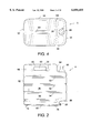
- FIG. 2 is a left side elevational view thereof
- FIG. 3 is a right side elevational view thereof
- FIG. 4 is a top plan view thereof
- FIG. 5 is a bottom plan view thereof
- FIG. 6 is a rear elevational view thereof
- FIG. 7 is a side elevational view illustrating a pair of caseless dispenser containers in stacked relation
- FIG. 8 is a perspective view taken generally from the top and right-hand side of a second preferred embodiment of a caseless dispenser container
- FIG. 9 is a perspective view taken generally from the bottom and right-hand side thereof.
- FIG. 10 is a front elevational view thereof
- FIG. 11 is a right side elevational view thereof, the left side elevational view being a substantial mirror image thereof;
- FIG. 12 is a rear elevational view thereof
- FIG. 13 is a top plan view thereof
- FIG. 14 is a bottom plan view thereof
- FIG. 15 is a cross-sectional view taken generally along the lines A--A of FIG. 11;
- FIG. 16 is a cross-sectional view taken generally along the lines B--B of FIG. 10;
- FIG. 17 is a cross-sectional view taken generally along the lines D--D of FIG. 10;
- FIG. 18 is a cross-sectional view taken generally along the lines E--E of FIG. 10;
- FIG. 19 is a cross-sectional view taken generally along the lines C--C of FIG. 10.
- FIG. 20 is a perspective view of the inventive containers in a preferred stacking relation.
- FIGS. 1-7 show a caseless dispenser container A which is in the general form of a parallelepiped.
- the dispenser of FIGS. 1-7 is, for example, a three (3) gallon caseless dispenser container used in the dairy industry. It will be appreciated that the invention is not limited to caseless dispenser containers used in the dairy industry but that this development finds particular application in this field because of the longstanding nature of the containers and shipping procedures used without substantial change over the years.
- Front and rear walls 30, 32 (FIG. 2) of the caseless dispenser container are disposed in generally parallel relation, as are side walls 34, 36, and the top and bottom surfaces 38, 40.
- the walls are integrally formed together from a blow molded, thin-walled plastic defining an interior cavity that stores the fluid product ultimately dispensed therefrom.
- At least one stiffening rib and as shown here, four stiffening ribs 50, 52, 54, 56 are employed for adding strength and rigidity to the structure.
- the ribs in the preferred embodiment are defined by continuous sidewall depressions, i.e., inwardly extending ribs, that extend about the entire periphery of the container in generally parallel relation about the front and rear walls 30, 32 and the sidewalls 34, 36.
- the strengthening ribs permit the structure to be formed from thin walls, thus achieving a reduction in the amount of plastic used relative to known containers, while still maintaining the desired strength and rigidity to stack containers one atop another as is presently achieved with separate shipping cases (stacking of the containers one atop another is best illustrated in FIG. 7). Accordingly, other strengthening rib configurations that achieve these objectives can be used without departing from the scope and intent of the subject invention.
- the goal of using a thin-walled structure while maintaining the ability to stack filled containers one on top another for ease of transport and storage, as well as substantial cost reductions associated with eliminating the shipping cases, is uniquely achieved with the preferred embodiment.
- integrally formed handle 60 is formed adjacent or as a part of the upper wall 38. Finger receiving opening 62 is defined beneath the handle and allows a user to easily grasp and handle the container.
- the handle is generally centered over the center of gravity of the container for ease in handling, although it will be understood that still other arrangements can be used without departing from the scope and intent of the subject invention.
- the upper surface of the handle 60 defines a substantial portion of the upper wall 38. This permits the downward or loading forces to be easily transferred from the upper wall to the front wall, rear wall, and the side walls of the container.
- the generally H-shaped configuration (FIG. 4) provides a suitable stable platform surface for supporting the next adjacent container stacked thereon while providing an ergonomic handle.
- other locations for the integrally formed handle are contemplated, although the location in the top wall is convenient since its configuration can add to the desired strength and load bearing features while still providing an easily accessed and ergonomically styled handle for carrying the container.
- a recess 64 is formed in the top wall 38, or disposed inwardly from the front wall 30.
- the recess 64 has a height and depth that accommodates a fill spout 66.
- the recess 64 is of suitable depth so that the fill spout 66 is functional and does not interfere with the stacking relationship of adjacent containers.
- the fill spout is of suitable diameter to allow rapid filling of the dairy product into the container.
- the fill opening subsequently serves as a vent opening during dispensing.
- the configuration of the bottom wall 40 is particularly illustrated in FIGS. 1, 2, 3, and 5. It has a slope or incline from the rear wall 32 toward the front wall 30 (FIGS. 2 and 3). As will be appreciated, the sloping surface facilitates draining of the fluid from the cavity when it is placed on a generally horizontal surface.
- feet 70, 72, 74, 76 extend outwardly at spaced, corner locations of the generally planar bottom wall 40.
- the individual feet have an elongated oval configuration (FIG. 5) that provides a suitable surface area for supporting the container.
- each of the feet has a generally domed configuration with generally planar central regions, providing a stable support for the container.
- the feet are also conveniently located to engage or rest on the parallel portions of the H-shaped upper wall 38 of a next adjacent container when disposed in stacked relation. This provides a column-like transfer of the weight or vertical forces from one container to another in the stacked position.
- the bottom surface has a slight V-shaped conformation or slope from side to side (FIG. 1).
- Portions 80, 82 extend from the respective sidewalls 34, 36. Each portion tapers downwardly from the respective sidewall intersecting at a generally centrally-running valley, which also tapers back-to-front toward the second or dispensing opening 84.
- the dual incline or sloped arrangement as described urges the fluid from the container.
- the dispensing opening is preferably formed in a recess 86 that extends upwardly from the bottom wall and inwardly from the front wall 30.
- the recess 86 is intended to allow easy container dispensing, even when disposed in stacked relation as shown in FIG. 7. Neither the vent opening 66 nor the dispensing opening 84 of adjacent containers overlap or obstruct the other's use in the preferred arrangement.
- the rear wall 32 may include an additional rib section 90.
- the strengthening rib extends over only the rear wall, again, to strengthen and rigidify the rear wall so as to transfer forces from the upper surface 30 to the lower surface 40.
- the lowermost rib 56 has a slightly modified or tapered entry, defining an inlet channel 92 (FIG. 3)to the remainder of the rib.
- the V-shaped walls defining the inwardly extending rib spread open or diverge from one another to receive a flexible dispensing hose 94 therein.
- the lowermost rib 56 serves the dual function of strengthening and rigidifying the container structure, while also serving as a storage means or storage recess area for the flexible tubing associated with the dispensing opening 84.
- the stacked relationship of dispensing containers is best shown in FIG. 7.
- the upper surface of the lower container supports the individual feet extending from the next adjacent upper container.
- Vertical forces are transferred generally evenly over the upper surface and, in addition, the bridging handle 60 provides added strength and rigidity between the parallel portions of the H-shaped top wall.
- the vertical forces are transferred down the side walls and the front and rear walls to the base or bottom.
- the strengthening ribs are removed from the illustration of FIG. 7 for simplification only and it will be recognized that the ribs serve a crucial function in the transfer of the vertical forces.
- the recesses 64, 86 are both located adjacent the front wall 30 of the respective containers so that adequate space is provided for manipulating the vent opening 66, as well as the dispensing opening 84 and the flexible tubing associated therewith.
- FIGS. 8-19 illustrate a second preferred embodiment of a caseless dispenser container, shown as a five (5) gallon container.
- like numerals refer to like elements and new numerals refer to new elements.
- the overall structure and function is the same of the containers is the same. That is, a series of generally parallel ribs are disposed substantially continuously about the periphery of the sidewalls and front and rear walls. Because of the increased size or capacity of this container, an additional one or two strengthening ribs 100, 102 are required.
- the ribs in this embodiment are also slightly different than those described with reference to FIGS. 1-7.
- the ribs are defined by generally U-shaped portions that do not extend about the entire periphery of the container, but do extend about substantially the entire periphery of the container.
- a rib may be defined by first and second U-shaped sections denoted by a, b. Terminal ends of these rib portions are defined in the sidewalls and are spaced adjacent an additional, vertically oriented rib 104. Again, this illustrates that the structural ribs need not adopt a predetermined configuration, but rather must be capable of effectively transferring forces from the upper wall to the base surface.
- the fill/vent opening is also disposed on a raised land 106 in the recess 64' of the top surface 38'.
- the venting structure (FIG. 10) preferably does not extend beyond the upper surface so that the vent is operable when the containers are in stacked relation.
- the feet have slightly different conformations.
- the feet disposed most closely adjacent the front wall i.e., 70', 76' are still of an elongated, oval configuration.
- the pair of feet 108, 110 disposed adjacent the rear wall have a hemispherical or rounded configuration.
- the location of the feet at spaced regions that coincide with the substantially planar, parallel regions of the H-shaped top surface advantageously transfers the vertical forces from one container to another disposed in stacked relation.
- the second preferred embodiment also adopts the dual taper or slope (i.e. from side to side by portions 80', 82', and the rear to front taper by the sloping bottom wall) provided in the bottom of the cavity so that fluid is effectively drained from the cavity and toward the dispensing opening 84'. This is best illustrated in FIGS. 10, 12 and 15-18.
- the dual function of the lowermost rib is retained in the second preferred embodiment. That is, the terminal end of the lowermost rib diverges open to receive the flexible hose that is connected at one end to the dispensing opening 84' and is squeezed between the sidewall that define the rib during storage.
- FIG. 20 illustrates one preferred conformation of stacking the containers one atop the other.
- the containers are disposed in horizontal relation so that the strengthening ribs are oriented in vertical fashion.
- the containers are arranged end to end on one level and then offset and arranged end to end on the next adjacent level. This provides a stable stacked array that advantageously transfers the vertical loads from one level to the other and ultimately to a supporting pallet or surface (not shown).
Abstract
Description
Claims (14)
Priority Applications (1)
| Application Number | Priority Date | Filing Date | Title |
|---|---|---|---|
| US09/390,926 US6050455A (en) | 1998-06-29 | 1999-09-07 | Caseless dispenser container |
Applications Claiming Priority (2)
| Application Number | Priority Date | Filing Date | Title |
|---|---|---|---|
| US09/114,244 US6068161A (en) | 1997-07-01 | 1998-06-29 | Stackable, thin-walled containers having a structural load distributing feature permitting caseless shipping |
| US09/390,926 US6050455A (en) | 1998-06-29 | 1999-09-07 | Caseless dispenser container |
Related Parent Applications (1)
| Application Number | Title | Priority Date | Filing Date |
|---|---|---|---|
| US09/114,244 Continuation-In-Part US6068161A (en) | 1997-07-01 | 1998-06-29 | Stackable, thin-walled containers having a structural load distributing feature permitting caseless shipping |
Publications (1)
| Publication Number | Publication Date |
|---|---|
| US6050455A true US6050455A (en) | 2000-04-18 |
Family
ID=22354149
Family Applications (1)
| Application Number | Title | Priority Date | Filing Date |
|---|---|---|---|
| US09/390,926 Expired - Lifetime US6050455A (en) | 1998-06-29 | 1999-09-07 | Caseless dispenser container |
Country Status (1)
| Country | Link |
|---|---|
| US (1) | US6050455A (en) |
Cited By (30)
| Publication number | Priority date | Publication date | Assignee | Title |
|---|---|---|---|---|
| US6474505B1 (en) * | 2000-12-29 | 2002-11-05 | Spartanburg Stainless Products, Inc. | Modular liquid container and dispensing system |
| US6588612B1 (en) | 2002-01-17 | 2003-07-08 | Plastipak Packaging, Inc. | Plastic container with stacking recesses |
| US20040007488A1 (en) * | 1997-07-01 | 2004-01-15 | Creative Edge Design Group, Ltd. | Increased reservoir for fluid container |
| US20040112926A1 (en) * | 2002-12-17 | 2004-06-17 | Burton Barnett | Fluid container |
| US20040178222A1 (en) * | 2002-05-23 | 2004-09-16 | Clausen Kenneth F. | Refrigerator liquid dispenser |
| US6854710B2 (en) | 2001-10-25 | 2005-02-15 | Illinois Tool Works Inc. | Valve assembly |
| USRE38785E1 (en) * | 1998-04-30 | 2005-08-30 | Ronald S. Carlson | Liquid storing and dispensing unit |
| US20060131334A1 (en) * | 2004-11-29 | 2006-06-22 | Carlson Ronald S | Stackable container for storing and dispensing liquid |
| US20060260971A1 (en) * | 2004-11-20 | 2006-11-23 | Consolidated Container Company Lp | Stackable containers and methods of manufacturing, stacking, and shipping the same |
| US20070095696A1 (en) * | 1997-07-01 | 2007-05-03 | Creative Edge Design Group, Ltd. | Stackable, thin-walled containers |
| US20070221606A1 (en) * | 2006-03-23 | 2007-09-27 | Eiten Carl T | Liquid Container |
| US20070246488A1 (en) * | 2006-04-20 | 2007-10-25 | Warren Cash | Container |
| US20070261983A1 (en) * | 2006-05-09 | 2007-11-15 | Silgan Plastics Corporation | Stacking containers |
| US20080035637A1 (en) * | 2006-08-09 | 2008-02-14 | Producers Dairy Foods, Inc. | Self-supporting liquid container for boxless storage, shipping and display |
| US20080217200A1 (en) * | 2007-03-05 | 2008-09-11 | Dean Intellectual Property Services Ii, L.P. | Stackable Liquid Container |
| US20090294453A1 (en) * | 2008-05-27 | 2009-12-03 | Christopher Brown | Stackable low permeation fuel tank |
| US20100206759A1 (en) * | 2007-03-05 | 2010-08-19 | Dean Intellectual Property ServicesII, Inc. | Stackable liquid container with tunnel-shaped base |
| US20110100856A1 (en) * | 2009-10-29 | 2011-05-05 | Michael Scot Rosko | Interlocking stacking container |
| US20120305554A1 (en) * | 2010-05-04 | 2012-12-06 | Brandal Johnston | Water Hose Cooler |
| US8403144B2 (en) | 2007-03-05 | 2013-03-26 | Dean Intellectual Property Services Ii, Inc. | Liquid container: system for distribution |
| WO2014164790A1 (en) * | 2013-03-11 | 2014-10-09 | Reeves Douglas E | Dual component packaging kit |
| US20160089647A1 (en) * | 2014-09-26 | 2016-03-31 | Carrier Corporation | Re-fillable syrup bin for beverage machine |
| USD764295S1 (en) | 2013-03-15 | 2016-08-23 | Mccormick & Company, Incorporated | Dispensing container for liquids |
| US9809353B2 (en) | 2013-03-15 | 2017-11-07 | Mccormick & Company, Incorporated | Dispensing container for liquids |
| US20170369204A1 (en) * | 2014-12-10 | 2017-12-28 | Dbh Enterprises, Inc. | Gravity assisted portable fuel container |
| US10246242B2 (en) | 2013-03-11 | 2019-04-02 | Douglas E. Reeves | Dual component packaging kit |
| US20190248552A1 (en) * | 2018-02-13 | 2019-08-15 | Stackcan Llc | Container Vent, Dispenser and Holding System |
| US10604311B2 (en) * | 2017-06-19 | 2020-03-31 | Carlisle Intangible, LLC | Rigid package for moisture-sensitive adhesive |
| US20210114771A1 (en) * | 2019-08-31 | 2021-04-22 | Winthrop Innovations, LLC | Storage tank with fluid transfer |
| US11072465B2 (en) * | 2016-03-21 | 2021-07-27 | The Sherwin-Williams Company | Storage container with spout |
Citations (6)
| Publication number | Priority date | Publication date | Assignee | Title |
|---|---|---|---|---|
| US1746332A (en) * | 1927-05-14 | 1930-02-11 | Henry E Barroll | Container |
| US3782602A (en) * | 1973-03-14 | 1974-01-01 | M Page | Frozen water containers with liquid dispenser for camping |
| US4372455A (en) * | 1980-01-18 | 1983-02-08 | National Can Corporation | Thin walled plastic container construction |
| US5163587A (en) * | 1989-12-11 | 1992-11-17 | Rehrig-Pacific Co. | Syrup delivery system |
| US5375741A (en) * | 1993-05-12 | 1994-12-27 | Encon, Inc. | Container for bulk material and its method of manufacture |
| US5794818A (en) * | 1995-11-09 | 1998-08-18 | Romeo-Rim, Inc. | Container for bulk materials |
-
1999
- 1999-09-07 US US09/390,926 patent/US6050455A/en not_active Expired - Lifetime
Patent Citations (6)
| Publication number | Priority date | Publication date | Assignee | Title |
|---|---|---|---|---|
| US1746332A (en) * | 1927-05-14 | 1930-02-11 | Henry E Barroll | Container |
| US3782602A (en) * | 1973-03-14 | 1974-01-01 | M Page | Frozen water containers with liquid dispenser for camping |
| US4372455A (en) * | 1980-01-18 | 1983-02-08 | National Can Corporation | Thin walled plastic container construction |
| US5163587A (en) * | 1989-12-11 | 1992-11-17 | Rehrig-Pacific Co. | Syrup delivery system |
| US5375741A (en) * | 1993-05-12 | 1994-12-27 | Encon, Inc. | Container for bulk material and its method of manufacture |
| US5794818A (en) * | 1995-11-09 | 1998-08-18 | Romeo-Rim, Inc. | Container for bulk materials |
Cited By (43)
| Publication number | Priority date | Publication date | Assignee | Title |
|---|---|---|---|---|
| US20070095696A1 (en) * | 1997-07-01 | 2007-05-03 | Creative Edge Design Group, Ltd. | Stackable, thin-walled containers |
| US7000794B2 (en) | 1997-07-01 | 2006-02-21 | Creative Edge Design Group, Ltd. | Increased reservoir for fluid container |
| US20040007488A1 (en) * | 1997-07-01 | 2004-01-15 | Creative Edge Design Group, Ltd. | Increased reservoir for fluid container |
| USRE38785E1 (en) * | 1998-04-30 | 2005-08-30 | Ronald S. Carlson | Liquid storing and dispensing unit |
| US6474505B1 (en) * | 2000-12-29 | 2002-11-05 | Spartanburg Stainless Products, Inc. | Modular liquid container and dispensing system |
| US6854710B2 (en) | 2001-10-25 | 2005-02-15 | Illinois Tool Works Inc. | Valve assembly |
| US6588612B1 (en) | 2002-01-17 | 2003-07-08 | Plastipak Packaging, Inc. | Plastic container with stacking recesses |
| US6935533B2 (en) * | 2002-05-23 | 2005-08-30 | Rubbermaid Incorporated | Refrigerator liquid dispenser |
| US20040178222A1 (en) * | 2002-05-23 | 2004-09-16 | Clausen Kenneth F. | Refrigerator liquid dispenser |
| US20040112926A1 (en) * | 2002-12-17 | 2004-06-17 | Burton Barnett | Fluid container |
| US7048150B2 (en) * | 2002-12-17 | 2006-05-23 | B&B Company, A California Partnership | Fluid container |
| US20060260971A1 (en) * | 2004-11-20 | 2006-11-23 | Consolidated Container Company Lp | Stackable containers and methods of manufacturing, stacking, and shipping the same |
| US7699171B2 (en) | 2004-11-20 | 2010-04-20 | Consolidated Container Company Lp | Stackable containers and methods of manufacturing, stacking, and shipping the same |
| US8544649B2 (en) | 2004-11-20 | 2013-10-01 | Consolidated Container Company Lp | Stackable containers and methods of manufacturing, stacking, and shipping the same |
| US8065857B2 (en) | 2004-11-20 | 2011-11-29 | Consolidated Container Company Lp | Stackable containers and methods of manufacturing, stacking, and shipping the same |
| US20100199609A1 (en) * | 2004-11-20 | 2010-08-12 | Consolidated Container Company Lp | Stackable containers and methods of manufacturing, stacking, and shipping the same |
| US20060131334A1 (en) * | 2004-11-29 | 2006-06-22 | Carlson Ronald S | Stackable container for storing and dispensing liquid |
| US20070221606A1 (en) * | 2006-03-23 | 2007-09-27 | Eiten Carl T | Liquid Container |
| US8893924B2 (en) * | 2006-04-20 | 2014-11-25 | Anthony B. Michellutti | Stackable container for storing and/or dispensing liquids |
| US20070246488A1 (en) * | 2006-04-20 | 2007-10-25 | Warren Cash | Container |
| US20070261983A1 (en) * | 2006-05-09 | 2007-11-15 | Silgan Plastics Corporation | Stacking containers |
| US20080035637A1 (en) * | 2006-08-09 | 2008-02-14 | Producers Dairy Foods, Inc. | Self-supporting liquid container for boxless storage, shipping and display |
| US8047392B2 (en) | 2007-03-05 | 2011-11-01 | Dean Intellectual Property Services Ii, Inc. | Stackable liquid container |
| US20100206759A1 (en) * | 2007-03-05 | 2010-08-19 | Dean Intellectual Property ServicesII, Inc. | Stackable liquid container with tunnel-shaped base |
| US8235214B2 (en) | 2007-03-05 | 2012-08-07 | Dean Intellectual Property Services Ii, Inc. | Stackable liquid container with tunnel-shaped base |
| US8403144B2 (en) | 2007-03-05 | 2013-03-26 | Dean Intellectual Property Services Ii, Inc. | Liquid container: system for distribution |
| US20080217200A1 (en) * | 2007-03-05 | 2008-09-11 | Dean Intellectual Property Services Ii, L.P. | Stackable Liquid Container |
| US20090294453A1 (en) * | 2008-05-27 | 2009-12-03 | Christopher Brown | Stackable low permeation fuel tank |
| US20110100856A1 (en) * | 2009-10-29 | 2011-05-05 | Michael Scot Rosko | Interlocking stacking container |
| US20120305554A1 (en) * | 2010-05-04 | 2012-12-06 | Brandal Johnston | Water Hose Cooler |
| WO2014164790A1 (en) * | 2013-03-11 | 2014-10-09 | Reeves Douglas E | Dual component packaging kit |
| US10246242B2 (en) | 2013-03-11 | 2019-04-02 | Douglas E. Reeves | Dual component packaging kit |
| USD764295S1 (en) | 2013-03-15 | 2016-08-23 | Mccormick & Company, Incorporated | Dispensing container for liquids |
| US9809353B2 (en) | 2013-03-15 | 2017-11-07 | Mccormick & Company, Incorporated | Dispensing container for liquids |
| US20160089647A1 (en) * | 2014-09-26 | 2016-03-31 | Carrier Corporation | Re-fillable syrup bin for beverage machine |
| US10035115B2 (en) * | 2014-09-26 | 2018-07-31 | Taylor Commercial Foodservice Inc. | Re-fillable syrup bin for beverage machine |
| US20170369204A1 (en) * | 2014-12-10 | 2017-12-28 | Dbh Enterprises, Inc. | Gravity assisted portable fuel container |
| US11072465B2 (en) * | 2016-03-21 | 2021-07-27 | The Sherwin-Williams Company | Storage container with spout |
| US11485546B2 (en) | 2016-03-21 | 2022-11-01 | The Sherwin-Williams Company | Storage container with spout |
| US10604311B2 (en) * | 2017-06-19 | 2020-03-31 | Carlisle Intangible, LLC | Rigid package for moisture-sensitive adhesive |
| US20190248552A1 (en) * | 2018-02-13 | 2019-08-15 | Stackcan Llc | Container Vent, Dispenser and Holding System |
| US10829277B2 (en) * | 2018-02-13 | 2020-11-10 | Stackcan Llc | Container vent, dispenser and holding system |
| US20210114771A1 (en) * | 2019-08-31 | 2021-04-22 | Winthrop Innovations, LLC | Storage tank with fluid transfer |
Similar Documents
| Publication | Publication Date | Title |
|---|---|---|
| US6050455A (en) | Caseless dispenser container | |
| US6851563B1 (en) | Rack apparatus for storing and handling water bottles | |
| US6772912B1 (en) | Liquid storage and dispensing tank | |
| US5544777A (en) | Stackable plastic container with drain sump and pallet and method of making the same | |
| US8047392B2 (en) | Stackable liquid container | |
| AU745454B2 (en) | Stackable re-usable container | |
| US8123034B2 (en) | Nestable crate for containers | |
| US7322475B2 (en) | Nestable crate for containers | |
| US20060137295A1 (en) | Increased reservoir for fluid container | |
| US20070114200A1 (en) | Stackable bottle system | |
| HU220513B1 (en) | Package tray for bottles | |
| US9637302B2 (en) | Economically improved plastic bottle and package system | |
| US20080035637A1 (en) | Self-supporting liquid container for boxless storage, shipping and display | |
| US3080096A (en) | Containers for flowable materials | |
| AU3555602A (en) | Nesting stacking crate | |
| WO1992008648A1 (en) | Container having multiple dispensing means | |
| US6076697A (en) | Crate for cartons | |
| WO1996003327A1 (en) | Crenelated container case | |
| NL8204341A (en) | SERVING DOCUMENT. | |
| CA2427561C (en) | Container for spoonable food products | |
| WO2001062615A1 (en) | Bulk container | |
| CA2093244C (en) | Stackable plastic drum with drain sump and pallet and method of making the same | |
| WO1997020742A1 (en) | Collapsible load carrier | |
| HU183909B (en) | Plastic shelf for storing and transporting produces being in cupor box | |
| NL9500077A (en) | Device for storing liquid, in particular aggressive liquid. |
Legal Events
| Date | Code | Title | Description |
|---|---|---|---|
| AS | Assignment |
Owner name: CREATIVE EDGE GROUP, LTD., OHIO Free format text: ASSIGNMENT OF ASSIGNORS INTEREST;ASSIGNORS:SOEHNLEN, GREGORY M.;PANASEWICZ, DALE;REEL/FRAME:010228/0704;SIGNING DATES FROM 19981231 TO 19990514 |
|
| AS | Assignment |
Owner name: CREATIVE EDGE DESIGN GROUP, LTD., OHIO Free format text: CORRECTIVE ASSIGNMENT TO CORRECT ASSIGNEE'S NAME THAT WAS PREVIOUSLY RECORDED ON REEL 010228, FRAME 0704;ASSIGNORS:SOEHNLEN, GREGORY M.;PANASEWICZ, DALE;REEL/FRAME:010711/0937;SIGNING DATES FROM 19981016 TO 19990514 |
|
| STCF | Information on status: patent grant |
Free format text: PATENTED CASE |
|
| FPAY | Fee payment |
Year of fee payment: 4 |
|
| AS | Assignment |
Owner name: WELLS FARGO BANK, NATIONAL ASSOCIATION, ACTING THR Free format text: SECURITY AGREEMENT;ASSIGNOR:CREATIVE EDGE DESIGN GROUP, LTD.;REEL/FRAME:018039/0026 Effective date: 20060629 |
|
| FPAY | Fee payment |
Year of fee payment: 8 |
|
| AS | Assignment |
Owner name: PACKAGING TECHNOLOGIES, INC., WASHINGTON Free format text: SECURITY AGREEMENT;ASSIGNOR:CREATIVE EDGE DESIGN GROUP, LTD.;REEL/FRAME:021371/0242 Effective date: 20080808 |
|
| FPAY | Fee payment |
Year of fee payment: 12 |
|
| AS | Assignment |
Owner name: CREATIVE EDGE DESIGN GROUP, LTD., OHIO Free format text: RELEASE BY SECURED PARTY;ASSIGNOR:WELLS FARGO BANK, NATIONAL ASSOCIATION;REEL/FRAME:058507/0854 Effective date: 20211229 |