US6056826A - Vacuum coating device for coating substrates on all sides - Google Patents
Vacuum coating device for coating substrates on all sides Download PDFInfo
- Publication number
- US6056826A US6056826A US09/118,078 US11807898A US6056826A US 6056826 A US6056826 A US 6056826A US 11807898 A US11807898 A US 11807898A US 6056826 A US6056826 A US 6056826A
- Authority
- US
- United States
- Prior art keywords
- leg
- longitudinal axis
- substrate holder
- substrate
- planet carrier
- Prior art date
- Legal status (The legal status is an assumption and is not a legal conclusion. Google has not performed a legal analysis and makes no representation as to the accuracy of the status listed.)
- Expired - Lifetime
Links
Images

Classifications
-
- C—CHEMISTRY; METALLURGY
- C23—COATING METALLIC MATERIAL; COATING MATERIAL WITH METALLIC MATERIAL; CHEMICAL SURFACE TREATMENT; DIFFUSION TREATMENT OF METALLIC MATERIAL; COATING BY VACUUM EVAPORATION, BY SPUTTERING, BY ION IMPLANTATION OR BY CHEMICAL VAPOUR DEPOSITION, IN GENERAL; INHIBITING CORROSION OF METALLIC MATERIAL OR INCRUSTATION IN GENERAL
- C23C—COATING METALLIC MATERIAL; COATING MATERIAL WITH METALLIC MATERIAL; SURFACE TREATMENT OF METALLIC MATERIAL BY DIFFUSION INTO THE SURFACE, BY CHEMICAL CONVERSION OR SUBSTITUTION; COATING BY VACUUM EVAPORATION, BY SPUTTERING, BY ION IMPLANTATION OR BY CHEMICAL VAPOUR DEPOSITION, IN GENERAL
- C23C14/00—Coating by vacuum evaporation, by sputtering or by ion implantation of the coating forming material
- C23C14/22—Coating by vacuum evaporation, by sputtering or by ion implantation of the coating forming material characterised by the process of coating
- C23C14/50—Substrate holders
- C23C14/505—Substrate holders for rotation of the substrates
Definitions
- the invention relates to a vacuum coating unit to coat substrates on all sides by rotating the substrates in a material flow.
- the invention can be employed with various methods of vacuum deposition, including cathodic sputtering, ion plating, CVD (chemical vapor deposition), and other related methods.
- the substrates can be individually mounted on shafts and brought into the vapor flow as the substrates rotate around the shaft axis.
- coggears or rollers which roll on a stationary toothed rack or rail, are affixed to the ends of the shafts. Resistance layers were already applied, in the indicated manner, on tubular insulators.
- a method also is already known for affixing geometrically simple substrates, such as optical lenses and filters, on substrate holders and conducting them through a vapor flow while periodically executing complicated compound movements.
- Such devices or methods are suitable only for relatively small substrates whose profiling does not cause any problems with respect to a uniform layer thickness distribution.
- a method for positioning the substrates on substrate holders which are arranged so they can rotate in an essentially cylindrical cage.
- the vaporizer source is located in the interior of the cage, so that, with one rotation of the cage, the substrates are moved through the vapor flow (which is directed upwards).
- the substrate holders then carry out an additional rotation within the cage because of a superimposed drive, which can be described as an involute movement. In this manner, a rather good layer thickness distribution is attained according to the law of chance.
- Substrates that are geometrically shaped in a particularly complicated manner, for which even greater importance is placed on a uniform layer thickness distribution, distribution of the alloy elements in the layer, and a great adhesive strength by intermetallic diffusion, are, for example, turbine buckets for gas turbines, as they are used in aviation.
- turbine buckets for gas turbines as they are used in aviation.
- the problems connected with surface layers on such turbine buckets are described in the company publication "High Temperature Resistant Coatings for Super-Alloy" by Richard P. Seeling and Dr. Richard J. Stueber from the Chromalloy American Corporation, New York, USA. It has been extraordinarily difficult up to now to produce such substrates having layers with the required characteristics on a large industrial scale and at economically justifiable prices.
- a vapor deposition unit for the coating of substrates on all sides by rotating the substrates in a material flow also is known and is disclosed in West German Patent No. 2,813,180.
- This unit consists of a vacuum chamber with an elongated material source having a longitudinal axis and a transverse axis.
- the unit also has a substrate holder with several fasteners for the flat arrangement of several substrates above the material source. More specifically, the substrate holder has two parallel carrier arms arranged in the shape of a fork, whose longitudinal axes are arranged mirror-symmetrically to a vertical symmetric plane passing through the longitudinal axis of the material source.
- the substrate holder also has couplings for the substrates, which are arranged on the interior sides of the carrier arms set on one another.
- the rotation axes of the couplings are aligned vertical to the symmetric plane, and a driving shaft is correlated with each of the carrier arms in their longitudinal direction, each driving shaft being connected via angular gears with couplings, on the one hand, and with a motor, on the other hand.
- U.S. Pat. No. 5,558,909 a device for the coating of three-dimensional substrates with comparatively large dimensions, such as gear rims for automobile tires, is known and disclosed in U.S. Pat. No. 5,558,909.
- two substrates are arranged on a carrier, which pivots in the coating chamber and which has a Z-shaped middle part bent at right angles.
- the substrates are mounted on shafts on one of the right-angle bends running at an incline with respect to the rotational axis of the carrier.
- the shafts extend at right angles to this right-angle bend, and are held by the right-angle bend and driven by a motor.
- the substrate carrier rotates, whereby the substrates mounted on the shafts rotate around the substrate carrier axis and, further, rotate around their own inclined longitudinal axes.
- the goal of the invention is to provide a vacuum coating unit of the kind described above, which makes it possible to provide several complicatedly shaped substrates, such as turbine buckets, with metal or oxidic surface layers in a particularly uniform manner.
- the vacuum coating unit is employed in a vacuum chamber for holding a material source, and includes a substrate holder for holding the substrates opposite the material source and a drive correlated with the substrate holder for the production of a rotation and a displacement movement of the substrates.
- the unit also has a hollow arm or extension subdivided into three legs, each leg extending at an angle with respect to one another.
- the first leg of the arm is formed at an obtuse angle with respect to the second leg, and the second and third legs are joined together at a knee which forms approximately a right angle.
- the substrates are held at the end of the third leg, such that the longitudinal axis of the first leg approximately intersects the center of the space where the substrates are held.
- the arm is driven by a motor around the longitudinal axis of the first leg in a rotating manner and, moreover, can be moved back and forth over a predetermined distance in the direction of this longitudinal axis.
- the substrates are connected with a shaft in a rotary-stationary ("mosfest") manner, while the shaft is constructed as a propeller (i.e., a universal drive) shaft or as a flexible shaft and is conducted through the hollow extension along the longitudinal axis of each leg.
- the free end of the shaft is operatively connected with a motor.
- the shaft is coupled with the motor on one end and is firmly joined with the planet carrier of a planetary gear system on the other end.
- the free end of the third leg of the hollow extension is provided with the sun gear of the planetary gear system, which supports and engages the planet gears. The axis of each planet gear is then firmly connected with a substrate holder.
- FIG. 1 illustrates the vacuum coating unit with a manipulator arm for holding four turbine buckets in a side view
- FIG. 2 illustrates the embodiment of the unit shown in FIG. 1, but with the manipulator arm swiveled by 90°;
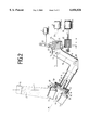
- FIG. 3 illustrates a top view of the planet gear and the substrate holders with the turbine buckets affixed on them in accordance with the embodiment shown in FIGS. 1 and 2.
- FIGS. 1-3 One preferred embodiment of the invention will now be described in detail, referring to FIGS. 1-3.
- a coating source 13 is situated stationary in a vacuum chamber, which is not depicted in detail.
- the coating source is suitable for coating the substrates 3, 3', 3", 3'"--in the represented case, four turbine buckets--with a wear-resistant and/or heat-resistant layer of material.
- the substrates 3, 3', 3", 3'" are affixed on a substrate holding device, which includes a hollow manipulator arm 6 having three legs 7, 8, and 9.
- the first two legs 7, 8 are connected at an obtuse angle ⁇ with respect to one another, while the second and third legs 8, 9 are connected at a right angle ⁇ with respect to one another.
- the legs 7, 8, 9 are constructed as hollow sections, which are joined firmly with one another or are constructed as an integral unit.
- a multipart driving shaft (formed from shaft links 14, 15, 16) passes through longitudinal boreholes in the three legs 7, 8, 9. (A detailed illustration of a section of shaft 16 is identified in FIGS. 1 and 2 by reference numeral 12.)
- the individual links of the shaft 14 are operatively connected by pairs of angular gears 17, 18.
- the shaft 14 is driven by a motor 21, whose rotations are transferred via the multipart shaft 14, 15, 16 to a holder 19 which holds the substrates 3, 3', 3", 3'".
- the holder 19 is connected to shaft 14, and includes a planetary gear system with a planet carrier 28 and four planet gears 30, 30', 30", 30'".
- the planet carrier 28 is connected in a stationary manner with the shaft 16, so that the planet carrier 28 turns with the shaft 16.
- the four planet gears 30, 30', 30", 30'" are supported on the planet carrier 28 in a rotatable manner, and each planet gear 30, 30', 30", 30'" engages a toothed sun gear 29 fixed on the end of the third leg 9 of the manipulator arm 6.
- each planet gear 30, 30', 30", 30'" is coupled with a substrate holder 32, 32', 32", 32'" through a shaft 31, 31', 31", 31'".
- the leg 7 is supported on a frame 20 in a rotatable manner.
- the leg 7 also has a toothed gear 23 fixedly mounted thereon, which in turn is coupled with a pinion 26.
- the pinion 26 is connected to a motor 10 through a shaft, so that the manipulator arm 6 can be rotated about axis 1 with the aid of the motor 10. For this reason, the manipulator arm 6 can assume the positions depicted in FIGS. 1 and 2.
- the manipulator arm 6 can be shifted by a distance "a" in a direction parallel to axis 1.
- the center of gravity A of the substrates 3, 3', 3", 3'" can be shifted by this distance a.
- a motor operator 11 is provided parallel to axis 1.
- the motor operator 11 moves a swiveling lever 22 via a rod, and the connecting link of this lever overlaps the toothed gear 23 and correspondingly shifts it.
- the shaft 24 of the motor 21 has a notched portion 27 which engages a slot 25 in the shaft 14 via a lifting cog, and is thus in operative connection with the multipart shaft 14, 15, 16.
- the shaft 24 of motor 21 transfers its rotation to the substrates 3, 3', 3", 3'", which are held by the substrate holders 32, 32', 32", 32'". Accordingly, opposite the operative axis b from the stationary coating source 13, the substrates 3,3',3",3'" can be shifted transversely by the extent a and thereby simultaneously also rotated around the axis m. Further, as will be understood from the description above, each substrate is also rotated about its own axis by the action of the planet gears 30, 30', 30", 30'".
- the substrates 3, 3', 3", 3'" can be shifted and turned in such a way with respect to coating source 13 that all parts of the jacket surfaces of the substrates can be uniformly coated by particle flow 2 of source 13. It is clear that instead of the four substrates 3, 3', 3", 3'" indicated in FIG. 3, another number of substrates can also be provided, if the planetary gear system or its planet carrier 28 is provided with a corresponding number of planet gears and substrate holders.
Abstract
Description
Claims (21)
Applications Claiming Priority (2)
| Application Number | Priority Date | Filing Date | Title |
|---|---|---|---|
| DE19730993A DE19730993B4 (en) | 1997-07-18 | 1997-07-18 | Vacuum coating device for coating substrates on all sides by rotation of the substrates in the particle stream |
| DE19730993 | 1997-07-18 |
Publications (1)
| Publication Number | Publication Date |
|---|---|
| US6056826A true US6056826A (en) | 2000-05-02 |
Family
ID=7836211
Family Applications (1)
| Application Number | Title | Priority Date | Filing Date |
|---|---|---|---|
| US09/118,078 Expired - Lifetime US6056826A (en) | 1997-07-18 | 1998-07-17 | Vacuum coating device for coating substrates on all sides |
Country Status (4)
| Country | Link |
|---|---|
| US (1) | US6056826A (en) |
| EP (1) | EP0892081B1 (en) |
| JP (1) | JPH1192930A (en) |
| DE (2) | DE19730993B4 (en) |
Cited By (10)
| Publication number | Priority date | Publication date | Assignee | Title |
|---|---|---|---|---|
| US20020183840A1 (en) * | 1998-06-05 | 2002-12-05 | Triflo Medical, Inc. | Mechanical heart valve |
| US20050034979A1 (en) * | 2003-08-11 | 2005-02-17 | Veeco Instruments Inc. | Method and apparatus for surface processing of a substrate |
| US20070246855A1 (en) * | 2006-04-21 | 2007-10-25 | Stephen Spruell | Method and Apparatus for Multi-Stream Metered Extrusion |
| US20080223291A1 (en) * | 2007-03-13 | 2008-09-18 | General Electric Company | Vacuum coater device and mechanism for supporting and manipulating workpieces in same |
| WO2009039261A1 (en) * | 2007-09-18 | 2009-03-26 | Veeco Instruments Inc. | Method and apparatus for surface processing of a substrate using an energetic particle beam |
| US20090098306A1 (en) * | 2003-08-11 | 2009-04-16 | Veeco Instruments Inc. | Method and Apparatus for Surface Processing of a Substrate Using an Energetic Particle Beam |
| US20100179346A1 (en) * | 2007-06-11 | 2010-07-15 | Norbert Klein | Method for hydrogenating glycerol |
| EP2540860A3 (en) * | 2011-06-27 | 2015-03-04 | United Technologies Corporation | Planetary manipulator for PVD coating system |
| TWI480403B (en) * | 2010-10-26 | 2015-04-11 | Hon Hai Prec Ind Co Ltd | Deposition device |
| US20150361556A1 (en) * | 2014-06-12 | 2015-12-17 | United Technologies Corporation | Deposition Apparatus and Use Methods |
Families Citing this family (3)
| Publication number | Priority date | Publication date | Assignee | Title |
|---|---|---|---|---|
| DE10116365C1 (en) * | 2001-04-02 | 2002-09-05 | Ald Vacuum Techn Ag | Supporting arm used for coating turbine blades comprises a holding device having a hollow shaft connected at its front end to a part to be coated |
| DE102004028348B4 (en) * | 2004-06-11 | 2006-12-21 | Mtu Aero Engines Gmbh | Process for coating components |
| AT513037B1 (en) * | 2012-09-21 | 2014-01-15 | Univ Wien Tech | Device for coating a substrate |
Citations (6)
| Publication number | Priority date | Publication date | Assignee | Title |
|---|---|---|---|---|
| US3783822A (en) * | 1972-05-10 | 1974-01-08 | J Wollam | Apparatus for use in deposition of films from a vapor phase |
| US4108107A (en) * | 1976-04-01 | 1978-08-22 | Airco, Inc. | Rotatable substrate holder for use in vacuum |
| DE2813180A1 (en) * | 1978-03-25 | 1979-10-04 | Leybold Heraeus Gmbh & Co Kg | VACUUM COATING SYSTEM FOR ALL SIDES COATING OF SUBSTRATES BY ROTATING THE SUBSTRATES IN THE MATERIAL FLOW |
| JPS62139878A (en) * | 1985-12-13 | 1987-06-23 | Toshiba Corp | Film forming device by plasma |
| DE29505497U1 (en) * | 1995-03-31 | 1995-06-08 | Balzers Hochvakuum | Coating station |
| US5558909A (en) * | 1996-01-17 | 1996-09-24 | Textron Automotive Interiors, Inc. | Apparatus and method for vacuum-metallizing articles with significant deposition onto three-dimensional surfaces |
Family Cites Families (2)
| Publication number | Priority date | Publication date | Assignee | Title |
|---|---|---|---|---|
| US4485759A (en) * | 1983-01-19 | 1984-12-04 | Multi-Arc Vacuum Systems Inc. | Planetary substrate support apparatus for vapor vacuum deposition coating |
| JP2592311B2 (en) * | 1988-10-19 | 1997-03-19 | 富士写真フイルム株式会社 | Method and apparatus for manufacturing magneto-optical recording medium |
-
1997
- 1997-07-18 DE DE19730993A patent/DE19730993B4/en not_active Expired - Fee Related
-
1998
- 1998-06-18 DE DE59814116T patent/DE59814116D1/en not_active Expired - Lifetime
- 1998-06-18 EP EP98111271A patent/EP0892081B1/en not_active Expired - Lifetime
- 1998-07-16 JP JP10201886A patent/JPH1192930A/en active Pending
- 1998-07-17 US US09/118,078 patent/US6056826A/en not_active Expired - Lifetime
Patent Citations (7)
| Publication number | Priority date | Publication date | Assignee | Title |
|---|---|---|---|---|
| US3783822A (en) * | 1972-05-10 | 1974-01-08 | J Wollam | Apparatus for use in deposition of films from a vapor phase |
| US4108107A (en) * | 1976-04-01 | 1978-08-22 | Airco, Inc. | Rotatable substrate holder for use in vacuum |
| DE2813180A1 (en) * | 1978-03-25 | 1979-10-04 | Leybold Heraeus Gmbh & Co Kg | VACUUM COATING SYSTEM FOR ALL SIDES COATING OF SUBSTRATES BY ROTATING THE SUBSTRATES IN THE MATERIAL FLOW |
| US4192253A (en) * | 1978-03-25 | 1980-03-11 | Leybold-Hereaus GmbH | Vacuum coating apparatus |
| JPS62139878A (en) * | 1985-12-13 | 1987-06-23 | Toshiba Corp | Film forming device by plasma |
| DE29505497U1 (en) * | 1995-03-31 | 1995-06-08 | Balzers Hochvakuum | Coating station |
| US5558909A (en) * | 1996-01-17 | 1996-09-24 | Textron Automotive Interiors, Inc. | Apparatus and method for vacuum-metallizing articles with significant deposition onto three-dimensional surfaces |
Cited By (23)
| Publication number | Priority date | Publication date | Assignee | Title |
|---|---|---|---|---|
| US20020183840A1 (en) * | 1998-06-05 | 2002-12-05 | Triflo Medical, Inc. | Mechanical heart valve |
| US20090098306A1 (en) * | 2003-08-11 | 2009-04-16 | Veeco Instruments Inc. | Method and Apparatus for Surface Processing of a Substrate Using an Energetic Particle Beam |
| US20050034979A1 (en) * | 2003-08-11 | 2005-02-17 | Veeco Instruments Inc. | Method and apparatus for surface processing of a substrate |
| US9206500B2 (en) | 2003-08-11 | 2015-12-08 | Boris Druz | Method and apparatus for surface processing of a substrate using an energetic particle beam |
| US20110089022A1 (en) * | 2003-08-11 | 2011-04-21 | Veeco Instruments Inc. | Method and apparatus for surface processing of a substrate |
| US7879201B2 (en) | 2003-08-11 | 2011-02-01 | Veeco Instruments Inc. | Method and apparatus for surface processing of a substrate |
| US8801987B2 (en) | 2006-04-21 | 2014-08-12 | Southwire Company, Llc | Method and apparatus for multi-stream metered extrusion |
| US20100247746A1 (en) * | 2006-04-21 | 2010-09-30 | Southwire Company | Method and Apparatus for Multi-Stream Metered Extrusion |
| US7754124B2 (en) | 2006-04-21 | 2010-07-13 | Southwire Company | Method and apparatus for multi-stream metered extrusion |
| US20070246855A1 (en) * | 2006-04-21 | 2007-10-25 | Stephen Spruell | Method and Apparatus for Multi-Stream Metered Extrusion |
| US20080223291A1 (en) * | 2007-03-13 | 2008-09-18 | General Electric Company | Vacuum coater device and mechanism for supporting and manipulating workpieces in same |
| EP1970463A3 (en) * | 2007-03-13 | 2009-02-25 | General Electric Company | Vacuum coater device and mechanism for supporting and manipulating workpieces in same |
| US7997227B2 (en) | 2007-03-13 | 2011-08-16 | General Electric Company | Vacuum coater device and mechanism for supporting and manipulating workpieces in same |
| US20100179346A1 (en) * | 2007-06-11 | 2010-07-15 | Norbert Klein | Method for hydrogenating glycerol |
| WO2009039261A1 (en) * | 2007-09-18 | 2009-03-26 | Veeco Instruments Inc. | Method and apparatus for surface processing of a substrate using an energetic particle beam |
| GB2465528B (en) * | 2007-09-18 | 2013-02-27 | Veeco Instr Inc | Method and apparatus for surface processing of a substrate using an energetic particle beam |
| GB2465528A (en) * | 2007-09-18 | 2010-05-26 | Vecco Instr Inc | Method and apparatus for surface processing of a substrate using an energetic particle beam |
| TWI480403B (en) * | 2010-10-26 | 2015-04-11 | Hon Hai Prec Ind Co Ltd | Deposition device |
| EP2540860A3 (en) * | 2011-06-27 | 2015-03-04 | United Technologies Corporation | Planetary manipulator for PVD coating system |
| US9109289B2 (en) | 2011-06-27 | 2015-08-18 | United Technologies Corporation | Manipulator for coating application |
| US20150361556A1 (en) * | 2014-06-12 | 2015-12-17 | United Technologies Corporation | Deposition Apparatus and Use Methods |
| US10889895B2 (en) * | 2014-06-12 | 2021-01-12 | Raytheon Technologies Corporation | Deposition apparatus and use methods |
| US11802339B2 (en) | 2014-06-12 | 2023-10-31 | Rtx Corporation | Deposition apparatus methods for sequential workpiece coating |
Also Published As
| Publication number | Publication date |
|---|---|
| DE19730993A1 (en) | 1999-01-21 |
| DE19730993B4 (en) | 2008-04-03 |
| EP0892081A2 (en) | 1999-01-20 |
| JPH1192930A (en) | 1999-04-06 |
| EP0892081A3 (en) | 2002-05-08 |
| DE59814116D1 (en) | 2007-12-20 |
| EP0892081B1 (en) | 2007-11-07 |
Similar Documents
| Publication | Publication Date | Title |
|---|---|---|
| US6056826A (en) | Vacuum coating device for coating substrates on all sides | |
| US4192253A (en) | Vacuum coating apparatus | |
| US5026469A (en) | Apparatus for holding and turning eyeglass lenses in a high-vacuum vapor deposition or sputtering system | |
| US5985036A (en) | Vacuum coating apparatus for overall coating of a substrate by rotation of the substrate in a stream of material | |
| EP0953656A3 (en) | Rotatable fixture for airfoils | |
| US2696662A (en) | Member to be used in thermic engines | |
| JPH05180280A (en) | Planet gear type gearing | |
| GB1562822A (en) | Vacuum deposition | |
| US5558909A (en) | Apparatus and method for vacuum-metallizing articles with significant deposition onto three-dimensional surfaces | |
| EP2540860A2 (en) | Planetary manipulator for PVD coating system | |
| US20020062791A1 (en) | Table | |
| TW201217561A (en) | Deposition device | |
| US20220341030A1 (en) | Metallic coating process for combustor panels using a barrel configuration | |
| WO2003035277A1 (en) | System for inverting substrate | |
| US5061356A (en) | Vacuum treatment apparatus and vacuum treatment method | |
| CN86205741U (en) | Coating device for physical vapor deposition | |
| US6632282B2 (en) | Planetary multi-substrate holder system for material deposition | |
| JP5721827B2 (en) | Vacuum coating apparatus and vacuum coating method | |
| JPH06108232A (en) | Method and apparatus for high ratio planetary drive for use in vacuum | |
| RU100519U1 (en) | INSTALLATION FOR APPLICATION OF NANOCOMPOSITE COATINGS ON PLANE SURFACES OF THE PARTS (OPTIONS) | |
| US20180312970A1 (en) | Vacuum chamber arrangement | |
| KR102592967B1 (en) | Atomic layer deposition apparatus and atomic layer deposition method | |
| EP4265819A1 (en) | Improved apparatus and method for coating articles by physical vapor deposition technique | |
| FR2465792A1 (en) | Vacuum vapour deposition appts. in which substrates are rotated - esp. suitable for producing corrosion resistant coatings on gas turbine blades | |
| EP4004253B1 (en) | Fixture to be used in pvd processes for cylindrical, elongated substrates |
Legal Events
| Date | Code | Title | Description |
|---|---|---|---|
| AS | Assignment |
Owner name: LEYBOLD SYSTEMS GMBH, GERMANY Free format text: ASSIGNMENT OF ASSIGNORS INTEREST;ASSIGNORS:RICK, ALFRED;EBERHARDT, HELMUT;ANDERLE, FRIEDRICH;AND OTHERS;REEL/FRAME:009653/0710;SIGNING DATES FROM 19981111 TO 19981201 |
|
| STCF | Information on status: patent grant |
Free format text: PATENTED CASE |
|
| FPAY | Fee payment |
Year of fee payment: 4 |
|
| AS | Assignment |
Owner name: ALD VACUUM TECHNOLOGIES AG, GERMANY Free format text: ASSIGNMENT OF ASSIGNORS INTEREST;ASSIGNOR:UNAXIS DEUTSCHLAND HOLDING GMBH;REEL/FRAME:016283/0121 Effective date: 20041117 Owner name: BALZERS UND LEYBOLD DEUTSCHLAND HOLDING AG, GERMAN Free format text: CHANGE OF NAME;ASSIGNOR:LEYBOLD SYSTEMS GMBH;REEL/FRAME:016290/0001 Effective date: 20001017 |
|
| AS | Assignment |
Owner name: UNAXIS DEUTSCHLAND HOLDING GMBH, GERMANY Free format text: CHANGE OF NAME;ASSIGNOR:BALZERS UND LEYBOLD DEUTSCHLAND HOLDING AG;REEL/FRAME:017575/0317 Effective date: 20010116 |
|
| FPAY | Fee payment |
Year of fee payment: 8 |
|
| FEPP | Fee payment procedure |
Free format text: PAYOR NUMBER ASSIGNED (ORIGINAL EVENT CODE: ASPN); ENTITY STATUS OF PATENT OWNER: LARGE ENTITY |
|
| FPAY | Fee payment |
Year of fee payment: 12 |