US6056907A - In situ-formed debond layer for fibers - Google Patents
In situ-formed debond layer for fibers Download PDFInfo
- Publication number
- US6056907A US6056907A US08/831,282 US83128297A US6056907A US 6056907 A US6056907 A US 6056907A US 83128297 A US83128297 A US 83128297A US 6056907 A US6056907 A US 6056907A
- Authority
- US
- United States
- Prior art keywords
- metal
- composite
- fibers
- silicon carbide
- process according
- Prior art date
- Legal status (The legal status is an assumption and is not a legal conclusion. Google has not performed a legal analysis and makes no representation as to the accuracy of the status listed.)
- Expired - Fee Related
Links
Images


Classifications
-
- C—CHEMISTRY; METALLURGY
- C04—CEMENTS; CONCRETE; ARTIFICIAL STONE; CERAMICS; REFRACTORIES
- C04B—LIME, MAGNESIA; SLAG; CEMENTS; COMPOSITIONS THEREOF, e.g. MORTARS, CONCRETE OR LIKE BUILDING MATERIALS; ARTIFICIAL STONE; CERAMICS; REFRACTORIES; TREATMENT OF NATURAL STONE
- C04B41/00—After-treatment of mortars, concrete, artificial stone or ceramics; Treatment of natural stone
- C04B41/009—After-treatment of mortars, concrete, artificial stone or ceramics; Treatment of natural stone characterised by the material treated
-
- C—CHEMISTRY; METALLURGY
- C04—CEMENTS; CONCRETE; ARTIFICIAL STONE; CERAMICS; REFRACTORIES
- C04B—LIME, MAGNESIA; SLAG; CEMENTS; COMPOSITIONS THEREOF, e.g. MORTARS, CONCRETE OR LIKE BUILDING MATERIALS; ARTIFICIAL STONE; CERAMICS; REFRACTORIES; TREATMENT OF NATURAL STONE
- C04B35/00—Shaped ceramic products characterised by their composition; Ceramics compositions; Processing powders of inorganic compounds preparatory to the manufacturing of ceramic products
- C04B35/622—Forming processes; Processing powders of inorganic compounds preparatory to the manufacturing of ceramic products
- C04B35/626—Preparing or treating the powders individually or as batches ; preparing or treating macroscopic reinforcing agents for ceramic products, e.g. fibres; mechanical aspects section B
- C04B35/628—Coating the powders or the macroscopic reinforcing agents
- C04B35/62844—Coating fibres
- C04B35/62857—Coating fibres with non-oxide ceramics
- C04B35/62873—Carbon
-
- C—CHEMISTRY; METALLURGY
- C04—CEMENTS; CONCRETE; ARTIFICIAL STONE; CERAMICS; REFRACTORIES
- C04B—LIME, MAGNESIA; SLAG; CEMENTS; COMPOSITIONS THEREOF, e.g. MORTARS, CONCRETE OR LIKE BUILDING MATERIALS; ARTIFICIAL STONE; CERAMICS; REFRACTORIES; TREATMENT OF NATURAL STONE
- C04B35/00—Shaped ceramic products characterised by their composition; Ceramics compositions; Processing powders of inorganic compounds preparatory to the manufacturing of ceramic products
- C04B35/622—Forming processes; Processing powders of inorganic compounds preparatory to the manufacturing of ceramic products
- C04B35/626—Preparing or treating the powders individually or as batches ; preparing or treating macroscopic reinforcing agents for ceramic products, e.g. fibres; mechanical aspects section B
- C04B35/628—Coating the powders or the macroscopic reinforcing agents
- C04B35/62844—Coating fibres
- C04B35/62876—Coating fibres with metals
-
- C—CHEMISTRY; METALLURGY
- C04—CEMENTS; CONCRETE; ARTIFICIAL STONE; CERAMICS; REFRACTORIES
- C04B—LIME, MAGNESIA; SLAG; CEMENTS; COMPOSITIONS THEREOF, e.g. MORTARS, CONCRETE OR LIKE BUILDING MATERIALS; ARTIFICIAL STONE; CERAMICS; REFRACTORIES; TREATMENT OF NATURAL STONE
- C04B35/00—Shaped ceramic products characterised by their composition; Ceramics compositions; Processing powders of inorganic compounds preparatory to the manufacturing of ceramic products
- C04B35/622—Forming processes; Processing powders of inorganic compounds preparatory to the manufacturing of ceramic products
- C04B35/64—Burning or sintering processes
- C04B35/645—Pressure sintering
- C04B35/6455—Hot isostatic pressing
-
- C—CHEMISTRY; METALLURGY
- C04—CEMENTS; CONCRETE; ARTIFICIAL STONE; CERAMICS; REFRACTORIES
- C04B—LIME, MAGNESIA; SLAG; CEMENTS; COMPOSITIONS THEREOF, e.g. MORTARS, CONCRETE OR LIKE BUILDING MATERIALS; ARTIFICIAL STONE; CERAMICS; REFRACTORIES; TREATMENT OF NATURAL STONE
- C04B35/00—Shaped ceramic products characterised by their composition; Ceramics compositions; Processing powders of inorganic compounds preparatory to the manufacturing of ceramic products
- C04B35/71—Ceramic products containing macroscopic reinforcing agents
- C04B35/78—Ceramic products containing macroscopic reinforcing agents containing non-metallic materials
- C04B35/80—Fibres, filaments, whiskers, platelets, or the like
-
- C—CHEMISTRY; METALLURGY
- C04—CEMENTS; CONCRETE; ARTIFICIAL STONE; CERAMICS; REFRACTORIES
- C04B—LIME, MAGNESIA; SLAG; CEMENTS; COMPOSITIONS THEREOF, e.g. MORTARS, CONCRETE OR LIKE BUILDING MATERIALS; ARTIFICIAL STONE; CERAMICS; REFRACTORIES; TREATMENT OF NATURAL STONE
- C04B41/00—After-treatment of mortars, concrete, artificial stone or ceramics; Treatment of natural stone
- C04B41/45—Coating or impregnating, e.g. injection in masonry, partial coating of green or fired ceramics, organic coating compositions for adhering together two concrete elements
- C04B41/4584—Coating or impregnating of particulate or fibrous ceramic material
-
- C—CHEMISTRY; METALLURGY
- C04—CEMENTS; CONCRETE; ARTIFICIAL STONE; CERAMICS; REFRACTORIES
- C04B—LIME, MAGNESIA; SLAG; CEMENTS; COMPOSITIONS THEREOF, e.g. MORTARS, CONCRETE OR LIKE BUILDING MATERIALS; ARTIFICIAL STONE; CERAMICS; REFRACTORIES; TREATMENT OF NATURAL STONE
- C04B2235/00—Aspects relating to ceramic starting mixtures or sintered ceramic products
- C04B2235/02—Composition of constituents of the starting material or of secondary phases of the final product
- C04B2235/50—Constituents or additives of the starting mixture chosen for their shape or used because of their shape or their physical appearance
- C04B2235/52—Constituents or additives characterised by their shapes
- C04B2235/5208—Fibers
- C04B2235/5216—Inorganic
- C04B2235/524—Non-oxidic, e.g. borides, carbides, silicides or nitrides
- C04B2235/5244—Silicon carbide
-
- Y—GENERAL TAGGING OF NEW TECHNOLOGICAL DEVELOPMENTS; GENERAL TAGGING OF CROSS-SECTIONAL TECHNOLOGIES SPANNING OVER SEVERAL SECTIONS OF THE IPC; TECHNICAL SUBJECTS COVERED BY FORMER USPC CROSS-REFERENCE ART COLLECTIONS [XRACs] AND DIGESTS
- Y10—TECHNICAL SUBJECTS COVERED BY FORMER USPC
- Y10T—TECHNICAL SUBJECTS COVERED BY FORMER US CLASSIFICATION
- Y10T428/00—Stock material or miscellaneous articles
- Y10T428/249921—Web or sheet containing structurally defined element or component
- Y10T428/249924—Noninterengaged fiber-containing paper-free web or sheet which is not of specified porosity
- Y10T428/249928—Fiber embedded in a ceramic, glass, or carbon matrix
-
- Y—GENERAL TAGGING OF NEW TECHNOLOGICAL DEVELOPMENTS; GENERAL TAGGING OF CROSS-SECTIONAL TECHNOLOGIES SPANNING OVER SEVERAL SECTIONS OF THE IPC; TECHNICAL SUBJECTS COVERED BY FORMER USPC CROSS-REFERENCE ART COLLECTIONS [XRACs] AND DIGESTS
- Y10—TECHNICAL SUBJECTS COVERED BY FORMER USPC
- Y10T—TECHNICAL SUBJECTS COVERED BY FORMER US CLASSIFICATION
- Y10T428/00—Stock material or miscellaneous articles
- Y10T428/29—Coated or structually defined flake, particle, cell, strand, strand portion, rod, filament, macroscopic fiber or mass thereof
- Y10T428/2913—Rod, strand, filament or fiber
- Y10T428/2933—Coated or with bond, impregnation or core
- Y10T428/2938—Coating on discrete and individual rods, strands or filaments
-
- Y—GENERAL TAGGING OF NEW TECHNOLOGICAL DEVELOPMENTS; GENERAL TAGGING OF CROSS-SECTIONAL TECHNOLOGIES SPANNING OVER SEVERAL SECTIONS OF THE IPC; TECHNICAL SUBJECTS COVERED BY FORMER USPC CROSS-REFERENCE ART COLLECTIONS [XRACs] AND DIGESTS
- Y10—TECHNICAL SUBJECTS COVERED BY FORMER USPC
- Y10T—TECHNICAL SUBJECTS COVERED BY FORMER US CLASSIFICATION
- Y10T428/00—Stock material or miscellaneous articles
- Y10T428/29—Coated or structually defined flake, particle, cell, strand, strand portion, rod, filament, macroscopic fiber or mass thereof
- Y10T428/2913—Rod, strand, filament or fiber
- Y10T428/2933—Coated or with bond, impregnation or core
- Y10T428/2962—Silane, silicone or siloxane in coating
-
- Y—GENERAL TAGGING OF NEW TECHNOLOGICAL DEVELOPMENTS; GENERAL TAGGING OF CROSS-SECTIONAL TECHNOLOGIES SPANNING OVER SEVERAL SECTIONS OF THE IPC; TECHNICAL SUBJECTS COVERED BY FORMER USPC CROSS-REFERENCE ART COLLECTIONS [XRACs] AND DIGESTS
- Y10—TECHNICAL SUBJECTS COVERED BY FORMER USPC
- Y10T—TECHNICAL SUBJECTS COVERED BY FORMER US CLASSIFICATION
- Y10T428/00—Stock material or miscellaneous articles
- Y10T428/29—Coated or structually defined flake, particle, cell, strand, strand portion, rod, filament, macroscopic fiber or mass thereof
- Y10T428/2913—Rod, strand, filament or fiber
- Y10T428/2933—Coated or with bond, impregnation or core
- Y10T428/2971—Impregnation
Definitions
- This invention relates to an in situ method for producing debond coating on silicon carbide fibers to be incorporated in a composite and the resulting product.
- a debonding coating is formed on fibers, and especially silicon carbide fibers, by forming a thin film of a metal or metal silicon alloy on silicon carbide fibers and annealing the fibers at a temperature sufficient to produce an effective amount of a metal silicide and carbon to form a debond coating on the silicon carbide fibers.
- These fibers having the debond coating can be added to composite forming materials and the mixture can be treated to form a consolidated composite.
- a more preferred way to make the consolidated composite is to place the silicon carbide fibers with the initial metal film coating into the composite forming materials and then to heat the mixture to form the debond coating in situ on the fibers and to form the consolidated composite.
- Preferred heating techniques include high temperature annealing, hot-pressing, or hot isostatic pressing (HIP).
- FIGS. 1 (a)-(d) presents schematic cross-sectional views of the silicon carbide fiber and the possible layers in the reaction products.
- FIG. 2 is a process flow sheet illustrating the two embodiments of the process invention.
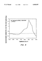
- FIG. 3 is differential scanning calorimetry heating trace (DSC) for the Ni/SiC multilayer sample.
- FIG. 4 is an X-ray diffraction scan (XRD) showing that the reaction product formed is Ni 2 Si.
- interphase modifications are required to control bonding between the fiber reinforcements and the matrix in composite materials.
- a debonding layer is beneficial for improving composite properties. Tailored debond layers promote multiple crack initiations, and crack deflection or branching during propagation, all of which absorb energy and make for tougher composite materials. Improved, in situ produced debond coatings have been formulated which may be used in composites to produce superior products.
- An in situ-formed debond coating may be synthesized by the following sequence. Using standard, low cost plating techniques, a thin film of nickel may be solution plated by either electrodeposition or electroless deposition on fibers in a SiC tow such as Nicalon fibers. A chemical coating technique, such as the two mentioned above, can penetrate the tow so that fewer missed or bare spots are anticipated. Further, the metal layer should be flexible so that spallation of the coating is minimized.
- Processing of the fibers into a composite would then proceed as normal such as with layup, matrix infiltration or coating, and consolidation.
- a high temperature anneal, hot-press, or hot isostatic pressing (HIP) would cause the nickel layer to react with the outermost portion of the SiC fiber and form nickel silicide, Ni 2 Si.
- Pressure is not required for the Ni+Si reaction to proceed. However, pressure is generally useful to consolidate the matrix phase of coated fibers.
- the carbon will either form small pockets or a complete layer in the interphase of the composite.
- the preferred temperature for carrying out the reaction is from about 350° C. to about 550° C.
- FIG. 1 (a) illustrates the cross-section of a silicon carbide fiber that has a thin coating of Ni prior to reaction. The amount of nickel deposited will control the amount of carbon released to form the debond layer.
- FIGS. 1 (b)-(d) show three potential scenarios for the debond layers after reaction.
- the resultant debond coating morphology will depend on the various surface and volume energies of the fiber, reaction products, and matrix as well as diffusion rates.
- the SiC fiber has a first inner layer of Ni 2 Si and an outer layer of carbon.
- the SiC fiber has an outer layer of a mechanically-weak mixture of carbon and Ni 2 Si.
- the SiC fiber has a first inner layer of carbon and an outer layer of Ni 2 Si. There is some evidence for the carbon collecting at the free surface (as in FIG. 1 (b)) when the Ni and SiC are reacted isolated from a matrix.
- the carbon reaction product is near the interface at all times. At the interface the carbon will perform its debonding function independent of which resultant morphology is produced. In either event, a weak mechanical bond or debonding layer is established between the remaining fiber and matrix. Clean deposition of a thin nickel layer will be the most important factor for quality control. When the nickel coating is applied, it is a layer. Once reacted, and especially if the mixture morphology occurs, the debond coating may not always be a "layer” anymore. It remains a coating, however, since it envelopes the fiber.
- the advantages of this direct technique are that the composite is easier and cheaper to fabricate. Due to more complete penetration of the fiber tow, the composite will have a better, more reliable performance during processing.
- the in situ formation of the debond layer means there is no extra processing steps required.
- the nickel-coated fibers also provide a high thermal conductivity path during heating. This process is shown on the left side of FIG. 2.
- the fibers with the pre-formed debond coating have to be embedded in a matrix to perform their debonding function. Conceivably, this could be done without heat, such as in the case of a cured polymer matrix. It is believed that all ceramic matrices would require heating. It is assumed in these processes that the chemical reactions caused by the heating will not destroy the carbon produced by the first reaction. For example, one would not want to put the fibers having the SiC/Ni 2 Si/C combination into an aluminum matrix because the Al and C would react to form aluminum carbide and there would no longer be a debond layer.
- metals besides nickel may be used in the practice of the invention.
- the function of the the metal thin film is to react with silicon carbide at the annealing temperature to form a debond coating of a metal silicide and carbon.
- Suitable metals in the invention are any metals that react with silicon carbide to form a metal silicide and carbon as reaction products.
- suitable metals include iron, copper, cobalt, tin, paladium, platinum and mixtures and alloys thereof.
- an Fe layer would perform in essentially the same manner as a nickel layer.
- nickel is preferred over iron because it would be difficult to electro-deposit the Fe as easily as the nickel, and oxidation of the Fe may become a problem.
- a metal silicon alloy may also be used, though it is less preferable.
- the two composite making processes result in products which may be in the same product if all the same materials were used in each case.
- some systems might be amenable to (1) the process where the metal coated fibers are placed in the composite and the consolidated composite is formed by heating with the simultaneous in situ-formed debond coating on the fibers or to (2) the process where the in situ-formed debond coating is first formed on the fibers and then these coated fibers are added to the composite, but not to both.
- This example illustrates the reaction which takes place between the adjacent Ni film and the silicon carbide.
- a Ni/SiC multilayer sample was synthesized as an analog of a fiber/matrix composite.
- the multilayer sample consisted of alternating Ni and SiC layers of equal thickness of 40 nm so that the bilayer pair was 80 nm.
- the total sample was made of 25 bilayers with a thickness of approximately 2,000 nm which is 2 microns.
- the multiple reaction interfaces mimic the numerous coated fiber interfaces found in composites and allows for easier determination of the reaction products via differential scanning calorimetry (DSC) and X-ray diffraction (XRD).
- FIG. 3 is the DSC output at a heating rate of 20° C. per minute for the Ni/SiC sample. It indicates a heat release and thus a chemical reaction was occurring. Samples which had been heat treated to specific temperatures and quenched were examined for reaction products by XRD. A temperature of 410° C. represents a temperature before the major peak in the DSC scan and a temperature of 510° C. represents a temperature after the major peak in the DSC scan.
- the XRD plot in FIG. 4 shows conclusively that one of the reaction products formed after the DSC scan to 510° C. was Ni 2 Si.
- the vertical, downward pointing arrows indicate the positions of expected x-ray diffraction peaks based upon previously published industry standard powder diffraction files. The number of the file or "card” is shown. The fact that three or more arrows line up establish that Ni 2 Si was present in the sample under analysis.
Abstract
A debonding layer is formed on fibers such as silicon carbide fibers by fing a thin film of a metal such as nickel or iron on the silicon carbide fibers and then annealing at a temperature of about 350-550° C. to form a debond layer of a metal silicide and carbon. These fibers having the debond coating can be added to composite forming materials and the mixture treated to form a consolidated composite. A one heating-step method to form a consolidated composite involves inserting the silicon carbide fibers with just the initial metal film coating into the composite forming materials and then heating the mixture to form the debond coating in situ on the fibers and to form the consolidated composite. Preferred heating techniques include high temperature annealing, hot-pressing, or hot isostatic pressing (HIP).
Description
1. Field of the Invention
This invention relates to an in situ method for producing debond coating on silicon carbide fibers to be incorporated in a composite and the resulting product.
2. Description of the Related Art
Current debond coatings are usually applied to fibers by chemical vapor deposition (CVD) or chemical vapor infiltration (CVI). These techniques are generally slow and costly. High temperatures, special atmospheres, special chemicals and special apparatus increase costs. Coatings sometimes contain defects due to touching fibers and incomplete spreading of fiber tows. Typical debond layer materials are carbon such as described by R. C. Loszewski in U.S. Pat. No. 5,024,889 and by H. Sakamoto in U.S. Pat. No. 5,055,430 and boron nitride as described by T. L. Jessen in U.S. Pat. No. 5,407,740 and R. Rice in U.S. Pat. No. 4,642,271. Special handling is generally used to prevent damage to the debond coatings. The ability to place a nickel coating on a fiber is shown by L. G. Morin in U.S. Pat. No. 4,942,090 on carbon fibers.
3. Objects of the Invention
It is an object of this invention to control bonding between the fiber reinforcements and the matrix in composite materials.
It is a further object of this invention to improve composite properties by providing a debonding layer on fibers in ceramic matrix composites.
It is a further object of this invention to provide tailored debond layers which absorb energy and make for tougher composite materials.
It is a further object of this invention to provide improved, in situ produced debond coatings on silicon carbide fibers which may be used in composites to produce superior products.
It is a further object of this invention to provide debond coatings on silicon carbide fibers where there is an outer layer containing nickel silicide, Ni2 Si, and carbon.
It is a further object of this invention to provide composite precursors where the composite forming material contains silicon carbide fibers with improved debond coatings.
These and further objects of the invention will become apparent as the description of the invention proceeds.
A debonding coating is formed on fibers, and especially silicon carbide fibers, by forming a thin film of a metal or metal silicon alloy on silicon carbide fibers and annealing the fibers at a temperature sufficient to produce an effective amount of a metal silicide and carbon to form a debond coating on the silicon carbide fibers. These fibers having the debond coating can be added to composite forming materials and the mixture can be treated to form a consolidated composite. A more preferred way to make the consolidated composite is to place the silicon carbide fibers with the initial metal film coating into the composite forming materials and then to heat the mixture to form the debond coating in situ on the fibers and to form the consolidated composite. Preferred heating techniques include high temperature annealing, hot-pressing, or hot isostatic pressing (HIP).
FIGS. 1 (a)-(d) presents schematic cross-sectional views of the silicon carbide fiber and the possible layers in the reaction products.
FIG. 2 is a process flow sheet illustrating the two embodiments of the process invention.
FIG. 3 is differential scanning calorimetry heating trace (DSC) for the Ni/SiC multilayer sample.
FIG. 4 is an X-ray diffraction scan (XRD) showing that the reaction product formed is Ni2 Si.
In general, interphase modifications are required to control bonding between the fiber reinforcements and the matrix in composite materials. For ceramic matrix composites a debonding layer is beneficial for improving composite properties. Tailored debond layers promote multiple crack initiations, and crack deflection or branching during propagation, all of which absorb energy and make for tougher composite materials. Improved, in situ produced debond coatings have been formulated which may be used in composites to produce superior products.
An in situ-formed debond coating may be synthesized by the following sequence. Using standard, low cost plating techniques, a thin film of nickel may be solution plated by either electrodeposition or electroless deposition on fibers in a SiC tow such as Nicalon fibers. A chemical coating technique, such as the two mentioned above, can penetrate the tow so that fewer missed or bare spots are anticipated. Further, the metal layer should be flexible so that spallation of the coating is minimized.
Processing of the fibers into a composite would then proceed as normal such as with layup, matrix infiltration or coating, and consolidation. During the final composite processing steps, a high temperature anneal, hot-press, or hot isostatic pressing (HIP), would cause the nickel layer to react with the outermost portion of the SiC fiber and form nickel silicide, Ni2 Si. Pressure is not required for the Ni+Si reaction to proceed. However, pressure is generally useful to consolidate the matrix phase of coated fibers.
Carbon must be released for this reaction to proceed since the reaction is:
4Ni+2SiC - - ->2Ni2 Si+2C
Depending on the heat treatment, the carbon will either form small pockets or a complete layer in the interphase of the composite. The preferred temperature for carrying out the reaction is from about 350° C. to about 550° C.
FIG. 1 (a) illustrates the cross-section of a silicon carbide fiber that has a thin coating of Ni prior to reaction. The amount of nickel deposited will control the amount of carbon released to form the debond layer.
FIGS. 1 (b)-(d) show three potential scenarios for the debond layers after reaction. The resultant debond coating morphology will depend on the various surface and volume energies of the fiber, reaction products, and matrix as well as diffusion rates. In FIG. 1 (b), the SiC fiber has a first inner layer of Ni2 Si and an outer layer of carbon. In FIG. 1 (c), the SiC fiber has an outer layer of a mechanically-weak mixture of carbon and Ni2 Si. In FIG. 1 (d), the SiC fiber has a first inner layer of carbon and an outer layer of Ni2 Si. There is some evidence for the carbon collecting at the free surface (as in FIG. 1 (b)) when the Ni and SiC are reacted isolated from a matrix. The short times and low temperatures involved in the reaction due to its large free energy change constrain the diffusion distance the carbon could achieve. Thus, the carbon reaction product is near the interface at all times. At the interface the carbon will perform its debonding function independent of which resultant morphology is produced. In either event, a weak mechanical bond or debonding layer is established between the remaining fiber and matrix. Clean deposition of a thin nickel layer will be the most important factor for quality control. When the nickel coating is applied, it is a layer. Once reacted, and especially if the mixture morphology occurs, the debond coating may not always be a "layer" anymore. It remains a coating, however, since it envelopes the fiber.
The advantages of this direct technique are that the composite is easier and cheaper to fabricate. Due to more complete penetration of the fiber tow, the composite will have a better, more reliable performance during processing. The in situ formation of the debond layer means there is no extra processing steps required. The nickel-coated fibers also provide a high thermal conductivity path during heating. This process is shown on the left side of FIG. 2.
An alternative procedure to make the composite is to form the debond layer at any time by heat treating the nickel-coated SiC fibers. Thus, if desirable, the debond layer could be formed prior to composite processing as shown on the right side of FIG. 4. This procedure, however, introduces an additional heating step.
The fibers with the pre-formed debond coating have to be embedded in a matrix to perform their debonding function. Conceivably, this could be done without heat, such as in the case of a cured polymer matrix. It is believed that all ceramic matrices would require heating. It is assumed in these processes that the chemical reactions caused by the heating will not destroy the carbon produced by the first reaction. For example, one would not want to put the fibers having the SiC/Ni2 Si/C combination into an aluminum matrix because the Al and C would react to form aluminum carbide and there would no longer be a debond layer.
Other metals besides nickel may be used in the practice of the invention. As described above with respect to nickel, the function of the the metal thin film is to react with silicon carbide at the annealing temperature to form a debond coating of a metal silicide and carbon. Suitable metals in the invention are any metals that react with silicon carbide to form a metal silicide and carbon as reaction products. Examples of other suitable metals include iron, copper, cobalt, tin, paladium, platinum and mixtures and alloys thereof. For example, an Fe layer would perform in essentially the same manner as a nickel layer. However, nickel is preferred over iron because it would be difficult to electro-deposit the Fe as easily as the nickel, and oxidation of the Fe may become a problem. A metal silicon alloy may also be used, though it is less preferable.
The two composite making processes result in products which may be in the same product if all the same materials were used in each case. However, some systems might be amenable to (1) the process where the metal coated fibers are placed in the composite and the consolidated composite is formed by heating with the simultaneous in situ-formed debond coating on the fibers or to (2) the process where the in situ-formed debond coating is first formed on the fibers and then these coated fibers are added to the composite, but not to both.
Having described the basic aspects of the invention, the following example is given to illustrate a specific embodiment thereof.
This example illustrates the reaction which takes place between the adjacent Ni film and the silicon carbide.
A Ni/SiC multilayer sample was synthesized as an analog of a fiber/matrix composite. The multilayer sample consisted of alternating Ni and SiC layers of equal thickness of 40 nm so that the bilayer pair was 80 nm. The total sample was made of 25 bilayers with a thickness of approximately 2,000 nm which is 2 microns. The multiple reaction interfaces mimic the numerous coated fiber interfaces found in composites and allows for easier determination of the reaction products via differential scanning calorimetry (DSC) and X-ray diffraction (XRD).
FIG. 3 is the DSC output at a heating rate of 20° C. per minute for the Ni/SiC sample. It indicates a heat release and thus a chemical reaction was occurring. Samples which had been heat treated to specific temperatures and quenched were examined for reaction products by XRD. A temperature of 410° C. represents a temperature before the major peak in the DSC scan and a temperature of 510° C. represents a temperature after the major peak in the DSC scan.
The XRD plot in FIG. 4 shows conclusively that one of the reaction products formed after the DSC scan to 510° C. was Ni2 Si. The vertical, downward pointing arrows indicate the positions of expected x-ray diffraction peaks based upon previously published industry standard powder diffraction files. The number of the file or "card" is shown. The fact that three or more arrows line up establish that Ni2 Si was present in the sample under analysis.
The carbon which is a by-product of the reaction, while not indicated in the XRD plot, must still be present due to mass conservation. Carbon is not easily observed by x-rays because carbon, being a low-Z element, does not scatter x-rays very effectively. The short times and low temperatures involved in the reaction constrain the diffusion distance the carbon could achieve. Thus, the carbon is inferred to be near the interface. At the interface the carbon will perform its debonding function. The higher modulus of the Ni2 Si is believed to make it very useful for debonding.
It is understood that the foregoing detailed description is given merely by way of illustration and that many variations may be made therein without departing from the spirit of this invention.
Claims (21)
1. A process of forming a debond coating on silicon carbide fibers comprising the steps of
a) forming a thin film of a metal or metal silicon alloy on silicon carbide fibers, wherein the metal or metal silicon alloy is selected as being capable of reacting with silicon carbide to form a metal silicide and carbon; and
b) annealing the fibers at a temperature sufficient to produce an effective amount of a metal silicide and carbon to form a debond coating on the silicon carbide fibers.
2. A process according to claim 1 wherein the annealing temperature is from 350° C. to 550° C.
3. A process according to claim 1, wherein the metal is selected from the group consisting of nickel, iron, copper, cobalt, tin, palladium, platinum and mixtures and alloys thereof.
4. A process according to claim 1, wherein the metal is nickel and the thin film of nickel is formed by solution plating.
5. A process according to claim 4, wherein the solution plating is by electrodeposition.
6. A process of forming a composite comprising the steps of:
a) forming a thin film of a metal or metal silicon alloy on silicon carbide fibers, wherein the metal or metal silicon alloy is selected as being capable of reacting with silicon carbide to form a metal silicide and carbon;
b) adding the coated fibers made in step (a) to a composite; and
c) heating the composite at a temperature sufficient to produce an effective amount of a metal silicide and carbon to form a debond coating on the silicon carbide fibers at or near the interface of the silicon carbide fibers in the composite.
7. A process according to claim 6 wherein the annealing temperature is from about 350° C. to about 550° C.
8. A process according to claim 6, wherein the metal is selected from the group consisting of nickel, iron, copper, cobalt, tin, palladium, platinum and mixtures and alloys thereof.
9. A process of forming a composite according to claim 6, wherein the heating is done by high temperature annealing, hot-pressing, or hot isostatic pressing (HIP).
10. A process of forming a composite according to claim 6, wherein the heating is done at a temperature of about 400° C.
11. A process according to claim 6, wherein the metal is nickel and the step of forming the thin film is by solution plating.
12. A process of forming a composite according to claim 6, wherein the heating is done under pressure.
13. A process of forming a composite comprising the steps of:
a) forming a thin film of a metal or metal silicon alloy on silicon carbide fibers, wherein the metal or metal silicon alloy is selected as being capable of reacting with silicon carbide to form a metal silicide and carbon;
b) annealing the fibers at a temperature sufficient to produce an effective amount of a metal silicide and carbon to form a debond coating on the silicon carbide fibers;
c) adding the fibers of step (b) to a composite; and
d) treating the composite of step (c) to form a consolidated composite.
14. A process according to claim 13 wherein the annealing temperature is from 350° C. to 550° C.
15. A process according to claim 13, wherein the metal is selected from the group consisting of nickel, iron, copper, cobalt, tin, palladium, platinum and mixtures and alloys thereof.
16. A process according to claim 13, where the treating of step (d) involves curing a polymer matrix.
17. A process according to claim 13, where the treating of step (d) involves heating to form the consolidated composite.
18. A process according to claim 17, wherein the heating is done by high temperature annealing.
19. A process according to claim 17, wherein the heating is done by hot-pressing.
20. A process according to claim 17, wherein the heating is done by hot isostatic pressing (HIP).
21. A process of forming a composite according to claim 13, wherein the annealing in step (b) is done at a temperature of about 400° C.
Priority Applications (2)
| Application Number | Priority Date | Filing Date | Title |
|---|---|---|---|
| US08/831,282 US6056907A (en) | 1997-03-31 | 1997-03-31 | In situ-formed debond layer for fibers |
| US09/518,926 US6376074B1 (en) | 1997-03-31 | 2000-03-03 | In situ-formed debond layer for fibers |
Applications Claiming Priority (1)
| Application Number | Priority Date | Filing Date | Title |
|---|---|---|---|
| US08/831,282 US6056907A (en) | 1997-03-31 | 1997-03-31 | In situ-formed debond layer for fibers |
Related Child Applications (1)
| Application Number | Title | Priority Date | Filing Date |
|---|---|---|---|
| US09/518,926 Division US6376074B1 (en) | 1997-03-31 | 2000-03-03 | In situ-formed debond layer for fibers |
Publications (1)
| Publication Number | Publication Date |
|---|---|
| US6056907A true US6056907A (en) | 2000-05-02 |
Family
ID=25258725
Family Applications (2)
| Application Number | Title | Priority Date | Filing Date |
|---|---|---|---|
| US08/831,282 Expired - Fee Related US6056907A (en) | 1997-03-31 | 1997-03-31 | In situ-formed debond layer for fibers |
| US09/518,926 Expired - Fee Related US6376074B1 (en) | 1997-03-31 | 2000-03-03 | In situ-formed debond layer for fibers |
Family Applications After (1)
| Application Number | Title | Priority Date | Filing Date |
|---|---|---|---|
| US09/518,926 Expired - Fee Related US6376074B1 (en) | 1997-03-31 | 2000-03-03 | In situ-formed debond layer for fibers |
Country Status (1)
| Country | Link |
|---|---|
| US (2) | US6056907A (en) |
Cited By (4)
| Publication number | Priority date | Publication date | Assignee | Title |
|---|---|---|---|---|
| US6228453B1 (en) * | 1995-06-07 | 2001-05-08 | Lanxide Technology Company, Lp | Composite materials comprising two jonal functions and methods for making the same |
| US20020122898A1 (en) * | 1999-01-27 | 2002-09-05 | Ringeisen Bradley R. | Generation of viable cell active biomaterial patterns by laser transfer |
| US6766764B1 (en) | 1999-01-27 | 2004-07-27 | The United States Of America As Represented By The Secretary Of The Navy | Matrix assisted pulsed laser evaporation direct write |
| US6936311B2 (en) | 1999-01-27 | 2005-08-30 | The United States Of America As Represented By The Secretary Of The Navy | Generation of biomaterial microarrays by laser transfer |
Families Citing this family (1)
| Publication number | Priority date | Publication date | Assignee | Title |
|---|---|---|---|---|
| WO2014159556A2 (en) | 2013-03-14 | 2014-10-02 | Rolls-Royce Corporation | Environmental barrier fiber coating |
Citations (7)
| Publication number | Priority date | Publication date | Assignee | Title |
|---|---|---|---|---|
| US5162271A (en) * | 1991-03-13 | 1992-11-10 | Northrop Corporation | Method of forming a ductile fiber coating for toughening non-oxide ceramic matrix composites |
| US5202059A (en) * | 1987-06-12 | 1993-04-13 | Lanxide Technology Company, Lp | Coated ceramic filler materials |
| US5580643A (en) * | 1987-06-12 | 1996-12-03 | Lanxide Technology Company, Lp | Composite materials and methods for making the same |
| US5593728A (en) * | 1994-11-01 | 1997-01-14 | Advanced Ceramics Corporation | Interface coating for ceramic fibers |
| US5682594A (en) * | 1987-06-12 | 1997-10-28 | Lanxide Technology Company, Lp | Composite materials and methods for making the same |
| US5707471A (en) * | 1991-12-20 | 1998-01-13 | Dow Corning Corporation | Method for making ceramic matrix composites |
| US5725825A (en) * | 1995-07-11 | 1998-03-10 | Minolta Co., Ltd. | Method of producing piezoelectric element |
Family Cites Families (8)
| Publication number | Priority date | Publication date | Assignee | Title |
|---|---|---|---|---|
| US4942090A (en) | 1982-03-16 | 1990-07-17 | American Cyanamid | Chaff comprising metal coated fibers |
| US4642271A (en) | 1985-02-11 | 1987-02-10 | The United States Of America As Represented By The Secretary Of The Navy | BN coating of ceramic fibers for ceramic fiber composites |
| JPS6212671A (en) | 1985-07-10 | 1987-01-21 | 株式会社日立製作所 | Fiber reinforced ceramics |
| US5024889A (en) | 1989-03-16 | 1991-06-18 | Avco Corporation | Surface treatment for silicon carbide filaments and product |
| US5045407A (en) | 1989-12-22 | 1991-09-03 | General Electric Company | Silicon carbide fiber-reinforced titanium base composites having improved interface properties |
| US5480707A (en) | 1993-10-06 | 1996-01-02 | Hyper-Thern High-Temperature Composites, Inc. | Toughened ceramic composite materials comprising coated refractory fibers in a ceramic matrix wherein the fibers are coated with carbon and an additional coating of ceramic material and carbon mixture |
| US5407740A (en) | 1994-01-07 | 1995-04-18 | The United States Of America As Represented By The Secretary Of The Navy | Ceramic composites with ceramic fibers |
| CA2175433A1 (en) | 1995-05-11 | 1996-11-12 | Gregg Alan Zank | Ceramic matrix composites using modified hydrogen silsesquioxane resin |
-
1997
- 1997-03-31 US US08/831,282 patent/US6056907A/en not_active Expired - Fee Related
-
2000
- 2000-03-03 US US09/518,926 patent/US6376074B1/en not_active Expired - Fee Related
Patent Citations (8)
| Publication number | Priority date | Publication date | Assignee | Title |
|---|---|---|---|---|
| US5202059A (en) * | 1987-06-12 | 1993-04-13 | Lanxide Technology Company, Lp | Coated ceramic filler materials |
| US5580643A (en) * | 1987-06-12 | 1996-12-03 | Lanxide Technology Company, Lp | Composite materials and methods for making the same |
| US5585165A (en) * | 1987-06-12 | 1996-12-17 | Lanxide Technology Company, Lp | Composite materials and methods for making the same |
| US5682594A (en) * | 1987-06-12 | 1997-10-28 | Lanxide Technology Company, Lp | Composite materials and methods for making the same |
| US5162271A (en) * | 1991-03-13 | 1992-11-10 | Northrop Corporation | Method of forming a ductile fiber coating for toughening non-oxide ceramic matrix composites |
| US5707471A (en) * | 1991-12-20 | 1998-01-13 | Dow Corning Corporation | Method for making ceramic matrix composites |
| US5593728A (en) * | 1994-11-01 | 1997-01-14 | Advanced Ceramics Corporation | Interface coating for ceramic fibers |
| US5725825A (en) * | 1995-07-11 | 1998-03-10 | Minolta Co., Ltd. | Method of producing piezoelectric element |
Cited By (5)
| Publication number | Priority date | Publication date | Assignee | Title |
|---|---|---|---|---|
| US6228453B1 (en) * | 1995-06-07 | 2001-05-08 | Lanxide Technology Company, Lp | Composite materials comprising two jonal functions and methods for making the same |
| US20020122898A1 (en) * | 1999-01-27 | 2002-09-05 | Ringeisen Bradley R. | Generation of viable cell active biomaterial patterns by laser transfer |
| US6766764B1 (en) | 1999-01-27 | 2004-07-27 | The United States Of America As Represented By The Secretary Of The Navy | Matrix assisted pulsed laser evaporation direct write |
| US6905738B2 (en) | 1999-01-27 | 2005-06-14 | The United States Of America As Represented By The Secretary Of The Navy | Generation of viable cell active biomaterial patterns by laser transfer |
| US6936311B2 (en) | 1999-01-27 | 2005-08-30 | The United States Of America As Represented By The Secretary Of The Navy | Generation of biomaterial microarrays by laser transfer |
Also Published As
| Publication number | Publication date |
|---|---|
| US6376074B1 (en) | 2002-04-23 |
Similar Documents
| Publication | Publication Date | Title |
|---|---|---|
| Meschter et al. | Silicide-matrix materials for high-temperature applications | |
| US5254397A (en) | Carbon fiber-reinforced composite material having a gradient carbide coating | |
| CA2275130C (en) | Composite material with ceramic matrix and sic fiber reinforcement, method for making same | |
| US5244748A (en) | Metal matrix coated fiber composites and the methods of manufacturing such composites | |
| EP0699642A2 (en) | Whisker or fiber reinforced polycrystalline cubic boron nitride and diamond | |
| US6056907A (en) | In situ-formed debond layer for fibers | |
| Mehan et al. | Interaction between silicon carbide and a nickel-based superalloy at elevated temperatures | |
| Frage et al. | The effect of Fe addition on the densification of B 4 C powder by spark plasma sintering | |
| Draper et al. | Compatibility of Fe–40Al with various fibers | |
| Tanaka et al. | Fabrication and evaluation of 3-dimensional tyranno fiber reinforced SiC composites by repeated infiltration of polycarbosilane | |
| EP0435039A1 (en) | Carbon fiber-reinforced composite material | |
| Everett et al. | In Situ-Formed Debond Layer for Fibers | |
| Edelstein et al. | OFFICE OF NAVAL RESEARCH DEPARTMENT OF THE NAVY CODE 00CC ARLINGTON VA 22217-5660 | |
| Banker | Metal matrix composite fabrication by liquid infiltration | |
| Nakano et al. | SIC and Si {sub 3} N {sub 4}-matrix composites according to the hot-pressing route | |
| EP0444426B1 (en) | Process for producing a silicon carbide whisker-reinforced silicon nitride composite material | |
| CN1325433C (en) | Ceramic-metal and ceramic-ceramic light composite material and manufacturing method thereof | |
| WO1989010432A1 (en) | Method of forming ceramic layer on metallic body | |
| JPH0881275A (en) | Production of fiber composite material having silicon carbide group | |
| Luo et al. | Effect of nickel on the interface and mechanical properties of SiCf/Cu composites | |
| Thornton | Fabrication of Metal Matrix Composite Materials | |
| Stinton | Ceramic composites by chemical vapor infiltration | |
| Sabouret et al. | Mechanical properties of continuous carbon fibre reinforced silicon nitride: Influence of fibre coatings | |
| JP3673011B2 (en) | Ceramic-based fiber composite material and manufacturing method thereof | |
| Boss et al. | Interface modification for fiber-reinforced titanium aluminide composites |
Legal Events
| Date | Code | Title | Description |
|---|---|---|---|
| AS | Assignment |
Owner name: NAVY, UNITED STATES OF AMERICA, THE, AS REPRESENTE Free format text: ASSIGNMENT OF ASSIGNORS INTEREST;ASSIGNORS:PEREPEZKO, JOHN H.;EVERETT, RICHARD K.;EDELSTEIN, ALAN S.;REEL/FRAME:008877/0777 Effective date: 19970331 |
|
| REMI | Maintenance fee reminder mailed | ||
| REMI | Maintenance fee reminder mailed | ||
| LAPS | Lapse for failure to pay maintenance fees | ||
| FP | Lapsed due to failure to pay maintenance fee |
Effective date: 20040502 |
|
| STCH | Information on status: patent discontinuation |
Free format text: PATENT EXPIRED DUE TO NONPAYMENT OF MAINTENANCE FEES UNDER 37 CFR 1.362 |