US6057805A - Broad band shaped element antenna - Google Patents
Broad band shaped element antenna Download PDFInfo
- Publication number
- US6057805A US6057805A US08/725,698 US72569896A US6057805A US 6057805 A US6057805 A US 6057805A US 72569896 A US72569896 A US 72569896A US 6057805 A US6057805 A US 6057805A
- Authority
- US
- United States
- Prior art keywords
- antenna
- elements
- triangular
- members
- megahertz
- Prior art date
- Legal status (The legal status is an assumption and is not a legal conclusion. Google has not performed a legal analysis and makes no representation as to the accuracy of the status listed.)
- Expired - Lifetime
Links
Images


Classifications
-
- H—ELECTRICITY
- H01—ELECTRIC ELEMENTS
- H01Q—ANTENNAS, i.e. RADIO AERIALS
- H01Q11/00—Electrically-long antennas having dimensions more than twice the shortest operating wavelength and consisting of conductive active radiating elements
- H01Q11/02—Non-resonant antennas, e.g. travelling-wave antenna
- H01Q11/10—Logperiodic antennas
-
- H—ELECTRICITY
- H01—ELECTRIC ELEMENTS
- H01Q—ANTENNAS, i.e. RADIO AERIALS
- H01Q5/00—Arrangements for simultaneous operation of antennas on two or more different wavebands, e.g. dual-band or multi-band arrangements
- H01Q5/40—Imbricated or interleaved structures; Combined or electromagnetically coupled arrangements, e.g. comprising two or more non-connected fed radiating elements
- H01Q5/48—Combinations of two or more dipole type antennas
-
- H—ELECTRICITY
- H01—ELECTRIC ELEMENTS
- H01Q—ANTENNAS, i.e. RADIO AERIALS
- H01Q9/00—Electrically-short antennas having dimensions not more than twice the operating wavelength and consisting of conductive active radiating elements
- H01Q9/04—Resonant antennas
- H01Q9/16—Resonant antennas with feed intermediate between the extremities of the antenna, e.g. centre-fed dipole
- H01Q9/28—Conical, cylindrical, cage, strip, gauze, or like elements having an extended radiating surface; Elements comprising two conical surfaces having collinear axes and adjacent apices and fed by two-conductor transmission lines
Definitions
- the present invention pertains to a broad band shaped element dipole antenna, particularly an apex fed opposed triangular element or "bowtie” antenna and a log periodic and triangular element antenna array, both including antenna elements extending normal to the plane of the triangular /elements at the distal ends of the triangular elements.
- Antennas used in analyzing electromagnetic radiation emissions from and the immunity of various devices to such radiation should have relatively broad band or so-called frequency independent operating capability.
- Such antennas should, also, desirably have minimum physical size and mechanical simplicity for portability as well as cost considerations.
- a half wave length dipole antenna is physically too large for many operating environments.
- physical size restraints often require the use of so-called electrically small antennas or antennas that resonate at a resonance frequency corresponding to about 0.1 wave length of the emitted or received signal.
- An antenna according to the invention in the above-referenced patent application includes a folded triangular element or "bowtie" dipole antenna which has been advantageous for minimizing antenna losses at the lower frequencies of the antenna frequency range than is possible with a conventional folded wire dipole antenna of the same physical size.
- Performance improvements for antennas which utilize the folded triangular shaped element dipole antenna in combination with a log periodic dipole array have also been realized with the antenna invention of the above-referenced patent application, which application is incorporated herein by reference.
- the folded triangular element antenna used alone, in combination with a log periodic antenna array or in combination with a single plane triangular shaped element antenna or a second folded triangular shaped element antenna may experience a phenomena known as mutual impedance which manifests itself as interference or parasitic coupling and caused by the folded triangular element antenna or the single plane triangular element antenna or the second folded triangular element antenna of an array.
- performance improvements may be obtained along the lines disclosed in the above-referenced patent application by providing a triangular element antenna without the complete folded configuration but constructed in accordance with the invention as described hereinbelow.
- the present invention provides an improved shaped element dipole antenna.
- the present invention also provides an improved shaped element dipole antenna and log periodic dipole antenna configured in an antenna array.
- the improved antenna and antenna array of the present invention is particularly adapted for measuring electromagnetic emissions from and the immunity of certain devices to such emissions, also known as electromagnetic compatibility testing. Such antenna are also useful in certain communications applications.
- a shaped element dipole antenna wherein opposed triangular shaped wire elements are connected to a signal source or a receiver and wherein the signal source or receiver is connected to the apex of each of the triangular elements and the triangular elements are physically and electrically connected to shaped wire elements which extend in planes substantially normal to the triangular shaped elements and may each have a generally rectangular configuration.
- the rectangular shaped elements may extend normal to the plane of the triangular shaped elements in one direction from such plane or in both directions.
- the antenna configuration of the present invention has a significantly lower resonance frequency than a so-called single wire dipole antenna of the same physical length and has the advantages of the antenna described in the above-referenced patent application while avoiding some of the mutual impedance or interference characteristics associated with a completely folded element antenna in accordance with the above-referenced patent application.
- the triangular element antenna with the transverse, generally rectangular shaped elements, in combination with a log periodic antenna array provides an antenna adapted for improved performance over a wide frequency range wherein a lower antenna factor (or higher gain) and a low voltage standing wave ratio (VSWR) characteristic is experienced at lower frequencies than is possible with a single triangular element (bowtie) antenna and log periodic antenna array or a folded bowtie antenna and log periodic antenna array of the same physical size.
- the antenna of the present invention also exhibits improved performance in an operating signal frequency range between the optimum frequency ranges of a log periodic dipole antenna array and the triangular element dipole antenna.
- the antenna of the present invention may be physically no larger than the antenna described and claimed in the above-referenced patent application, is mechanically less complicated, lighter in weight and may enjoy all of the advantages of the antennas described in the referenced patent application.
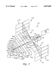
- FIG. 1 is a perspective view of a broad band shaped element antenna in accordance with the invention
- FIG. 2 is a perspective view of an alternate embodiment of an antenna in accordance with the invention.
- FIG. 2A is a schematic diagram for an antenna in accordance with the invention.
- FIG. 3 is a perspective view of a modified antenna similar to the embodiment shown in FIG. 2;
- FIGS. 4 through 6 are diagrams showing the performance characteristics of the antenna embodiment illustrated in FIG. 2.
- the antenna 10 is characterized by a pair of opposed triangular shaped antenna elements 12 and 14, having respective apexes 16 and 18 supported on a suitable support member 20.
- the triangular antenna element 12 has opposed, diverging, wire or metal tube outer strut members 22 and 24 interconnected by a base member 26 to form the triangular shaped element 12.
- the strut members 22 and 24 are also interconnected or merged with each other at the apex 16.
- Intermediate spaced apart diverging strut members 28 and 30 also extend between apex 16 and the base member 26.
- the triangular element 14 is also provided with opposed diverging strut members 22 and 24, a base member 26 and intermediate strut members 28 and 30 arranged in the same configuration as antenna element 12.
- the antenna 10 is further provided with transverse antenna elements 32 and 34 which are each characterized as respective rectangular wire or metal tube shaped elements having spaced apart strut members 36 and 38 generally parallel to the base members 26 and which are interconnected by plural, spaced apart generally parallel strut members 40, 42, 44 and 46 extending normal to strut members 36 and 38.
- the strut members 40, 42, 44 and 46 are connected, preferably, midway between their opposite ends to the base member 26 of each triangular antenna element 12 and 14.
- the support 20 may be connected to a further support member 48, comprising a boom or mast through which suitable conductors 50 and 52 are trained and are connected to the respective antenna apexes 16 and 18.
- the conductors 50 and 52 are also connected to a suitable balun transformer 54 disposed in an enclosure 56.
- the transformer 54 is connected to a suitable signal source 60, the reciprocal of which may be a receiver.
- the transverse antenna elements 32 and 34 have been determined to improve the performance of a triangular element or so-called "bowtie" antenna without causing some of the mutual impedance or interference problems associated with a folded triangular element antenna, at least with respect to operating at certain receiving or transmitting frequencies.
- the antenna elements 32 and 34 preferably extend in planes normal to the plane of the antenna elements 12 and 14. Although the plane of the antenna elements 12 and 14 may be the same, or the antenna elements 12 and 14 may be disposed in planes which are slightly offset from each other but parallel to each other, for purposes of this discussion it will be assumed that the antenna elements 12 and 14 are substantially coplanar and the antenna elements 32 and 34 extend in planes substantially parallel to each other but normal to the plane of the elements 12 and 14. Still further, the antenna elements 32 and 34 may be configured such that they extend in only one direction from the plane of the antenna elements 12 and 14, respectively, rather than being configured to extend substantially equidistant in opposite directions from the planes of the antenna elements 12 and 14, as illustrated in FIG. 1.
- An antenna 10 having an overall length, 1, between base members 26 of the respective antenna elements 12 and 14 of about 1.30 meters, an included angle between elements 22 and 24 of about sixty degrees at the respective apexes, an included angle of about twenty degrees between strut members 28 and 30, an overall width, b, of elements 32 and 34 of about 0.60 meters, a dimension b' of about 0.30 meters and a length or height, c, of elements 26, 36 and 38 of about 0.75 meters is suitable for operating frequencies in the range of twenty to two hundred megahertz.
- the struts described may be welded at their contiguous points.
- the diameters of the struts 22, 24, 26, 28, 30, 36, 38, 40, 42, 44 and 46 may be about 12.7 mm for an antenna having the other physical dimensions discussed hereinabove.
- the struts may be of other cross-sectional configurations and cross-sectional dimensions, if desired.
- the intermediate strut members 28, 30, 42 and 44 are desirable but are not required for inclusion in an antenna in accordance with the present invention.
- the antenna 80 includes the triangular element antenna shown in FIG. 1, that is, including the opposed triangular elements 12 and 14 and the respective transverse antenna elements 32 and 34 connected thereto, respectively.
- the apexes 16 and 18 are mechanically and electrically connected to spaced apart elongated boom members 82 and 84, formed of suitable conductive metal tubing, for example.
- the booms 82 and 84 may be mechanically connected to the aforementioned balun transformer enclosure 56, which is preferably constructed of a suitable non-conductive material.
- the boom members 82 and 84 also support a log periodic antenna array, generally designated by numeral 88, spaced along the boom members, as shown, and characterized by plural, opposed wire or metal tube dipole antenna elements of respective lengths required for transmitting and receiving radiation of selected frequencies, in a known manner.
- Representative ones of the opposed wire dipole elements of array 88 are shown and indicated by numerals 90a, 90b, 92a, 92b, 94a and 94b, 96a, 96b, 98a, 98b and so on through 108a, 108b, as shown in FIG. 2.
- twenty-three wire dipole antennas may be mounted on booms 82 and 84, by way of example, for an antenna operating at frequencies between twenty megahertz and two gigahertz. More or fewer dipole elements may be provided.
- the antennas described herein, for operation at twenty megahertz to two hundred megahertz may have ten dipole elements, for example.
- Alternate antenna elements on the opposite side of longitudinal centerline or axis 110 of antenna 80 are connected to respective ones of the booms 82 and 84 to provide the desired phase relationship for signals received or emitted by the antenna 80.
- Signal reception or transmission from source 60 is communicated to the distal ends 82a and 84a of the booms 82 and 84 by suitable conductors 112 and 114 which are electrically connected to source 60 through the aforementioned balun transformer 54 or as otherwise described herein.
- the balun 54 comprises a so-called common mode choke.
- FIG. 2A an arrangement as shown in FIG. 2A is actually preferred for blocking common mode currents in the boom conductors 82 and 84.
- a coaxial cable comprising the conductors 112 and 114 may be connected directly to source 60 and the outer conductor of the coaxial cable may form two parallel inductors which block common mode currents from capacitively coupling to the coaxial cable outer conductor creating an asymmetric operating condition.
- the parallel inductors of the aforementioned coaxial cable may also be tapped to provide some impedance matching to the capacitive impedance of the bowtie antenna. A schematic diagram illustrating this arrangement is shown in FIG. 2A.
- FIG. 3 another embodiment of an antenna similar to the antenna 80 is illustrated and generally designated by the numeral 81.
- the antenna 81 is substantially the same as the antenna 80 except the transverse rectangular elements 32 and 34 are replaced by elements 33 and 35, respectively, which extend in only one direction from the plane of the elements 12 and 14.
- the elements 33 and 35 may extend in a direction away from the log periodic antenna array 88 or in a direction toward the log periodic antenna array 88, as indicated by the alternate positions of element 33 and 35.
- the loading of the antenna elements 12 and 14 provided by the antenna elements 33 and 35 is expected to improve the performance of an antenna such as the antenna 81 in the frequency range discussed herein for the antennas 10 and 80.
- any of antennas 10, 80 or 81 lumped impedances 47, FIG. 1 may be utilized to modify antenna loading.
- FIG. 4 there is illustrated a diagram of antenna factor in decibels versus frequency in megahertz for the antenna 80 as compared with a similar antenna having triangular shaped or bowtie elements without the transverse elements 32 and 34 of the present invention.
- the dashed line curve 70 in FIG. 4 represents the antenna factor for the aforementioned antenna without the transverse elements 32 and 34 while the solid line 72 indicates the antenna factor for the antenna 80.
- FIG. 4 it will be noted from FIG. 4 that in a range of frequencies between about 75 megahertz to 200 megahertz, there is not a significant difference in the antenna factor between the two types of antennas. However, in a frequency range of transmitted or received signals of between about 25 megahertz to 70 megahertz, the antenna 80 shows marked improvement.
- antenna factor for the antennas described and claimed
- gain is applicable for applications of the antennas for transmitting electromagnetic radiation
- antenna factor is the figure of merit or applications wherein the antenna is receiving electromagnetic radiation signals.
- high gain is desirable under the same circumstances that a low antenna factor is desirable, depending on the application of the antenna.
- the ranges of frequencies discussed herein with respect to FIGS. 4 through 6, are for the antenna having the dimensions described above.
- the frequencies at which the antenna 80, for example, will show marked improvements will vary also.
- the optimum frequency range will be twelve megahertz to thirty-five megahertz and if the size of the antenna 80 is half that described above, the optimum frequency range discussed would be approximately fifty megahertz to one hundred forty megahertz.
- FIG. 5 there is illustrated a diagram of voltage standing wave ratio (VSWR) versus frequency in megahertz comparing the performance of the antenna 80, as indicated by the solid line 71, with the performance of a single plane bowtie and log periodic antenna, described in conjunction with FIG. 4, as indicated by the dashed line 73.
- VSWR voltage standing wave ratio
- FIG. 5 there is essentially no difference in VSWR for signals transmitted or received by the two types of antennas in a frequency range of between about 110 megahertz to 300 megahertz.
- the antenna 80 has a higher VSWR between about 62 megahertz and 130 megahertz, this VSWR is below a level of about 10:1, which is acceptable for many antenna applications, including those contemplated by the present invention.
- FIG. 5 voltage standing wave ratio
- the antenna 80 has an acceptable VSWR for operation in a frequency range of about 35 to 62 megahertz and, in particular, antenna 80 has an acceptable VSWR for operating frequencies lower than the capabilities of the antenna with the single plane triangular element or bowtie antenna.
- the comparisons of FIGS. 4 and 5 are for antennas having the same dimensions except, of course, for the addition of the transverse antenna elements 32 and 34. It should be mentioned that in electromagnetic compatibility testing, antennas with a VSWR of greater than 10:1 are commonly used. A VSWR of 100:1 may be experienced in some cases.
- the antenna factor and/or gain determines the low operating frequency limit, that is, an antenna factor of less than about 15 decibels.
- FIG. 6 there is illustrated a diagram of antenna factor in decibels versus frequency in megahertz for the antenna 80 as compared with an antenna having the same physical features and dimensions except for the use of a folded triangular element antenna in the array.
- the dashed curved line 77 in FIG. 6 represents the antenna factor versus frequency for a log periodic antenna array with a folded triangular element antenna in combination and indicating that in a frequency range of between about 65 megahertz to 105 megahertz, the antenna factor for the aforementioned antenna becomes greater than 10 decibels, an undesired characteristic.
- the solid line curve 79 in FIG. 6 is, as shown, a smoother curve, that is one having fewer abrupt changes in slope.
- antennas 10, 80 and 81 and the components included therein are believed to be within the purview of one of ordinary skill in the art of broad band antennas based on the foregoing description. Those elements not described in detail may be constructed using conventional materials for antennas for receiving and transmitting electromagnetic radiation in the frequency ranges indicated herein.
Abstract
Description
Claims (2)
Priority Applications (2)
| Application Number | Priority Date | Filing Date | Title |
|---|---|---|---|
| US08/725,698 US6057805A (en) | 1996-08-19 | 1996-10-03 | Broad band shaped element antenna |
| EP97113881A EP0825675A3 (en) | 1996-08-19 | 1997-08-12 | Broad band shaped element dipole antenna |
Applications Claiming Priority (2)
| Application Number | Priority Date | Filing Date | Title |
|---|---|---|---|
| US08/699,469 US5945962A (en) | 1996-08-19 | 1996-08-19 | Broad band shaped element dipole antenna |
| US08/725,698 US6057805A (en) | 1996-08-19 | 1996-10-03 | Broad band shaped element antenna |
Related Parent Applications (1)
| Application Number | Title | Priority Date | Filing Date |
|---|---|---|---|
| US08/699,469 Continuation-In-Part US5945962A (en) | 1996-08-19 | 1996-08-19 | Broad band shaped element dipole antenna |
Publications (1)
| Publication Number | Publication Date |
|---|---|
| US6057805A true US6057805A (en) | 2000-05-02 |
Family
ID=27106436
Family Applications (1)
| Application Number | Title | Priority Date | Filing Date |
|---|---|---|---|
| US08/725,698 Expired - Lifetime US6057805A (en) | 1996-08-19 | 1996-10-03 | Broad band shaped element antenna |
Country Status (2)
| Country | Link |
|---|---|
| US (1) | US6057805A (en) |
| EP (1) | EP0825675A3 (en) |
Cited By (16)
| Publication number | Priority date | Publication date | Assignee | Title |
|---|---|---|---|---|
| US6323821B1 (en) * | 1999-03-23 | 2001-11-27 | Tdk Rf Solutions, Inc. | Top loaded bow-tie antenna |
| US6329955B1 (en) * | 1998-10-26 | 2001-12-11 | Tdk Rf Solutions Inc. | Broadband antenna incorporating both electric and magnetic dipole radiators |
| US6483476B2 (en) * | 2000-12-07 | 2002-11-19 | Telex Communications, Inc. | One-piece Yagi-Uda antenna and process for making the same |
| WO2003034535A1 (en) * | 2001-10-15 | 2003-04-24 | Terk Technologies Corporation | Integral antenna for satellite radio band, television band and fm radio band |
| US6677913B2 (en) * | 2001-06-19 | 2004-01-13 | The Regents Of The University Of California | Log-periodic antenna |
| US6842156B2 (en) | 2001-08-10 | 2005-01-11 | Amplifier Research Corporation | Electromagnetic susceptibility testing apparatus |
| US20050145334A1 (en) * | 2002-07-03 | 2005-07-07 | Tokyo Electron Limited | Method and apparatus for non-invasive measurement and analysis of semiconductor process parameters |
| US6975278B2 (en) | 2003-02-28 | 2005-12-13 | Hong Kong Applied Science and Technology Research Institute, Co., Ltd. | Multiband branch radiator antenna element |
| US20070241982A1 (en) * | 2004-09-30 | 2007-10-18 | Alan Stigliani | Contoured triangular dipole antenna |
| US7432872B1 (en) * | 2007-04-27 | 2008-10-07 | The United States Of America As Represented By The Secretary | Compact aviation vertically polarized log periodic antenna |
| US20100302118A1 (en) * | 2009-05-28 | 2010-12-02 | Winegard Company | Compact high definition digital television antenna |
| CN104198834A (en) * | 2014-07-30 | 2014-12-10 | 中国电子科技集团公司第三十研究所 | Vehicle electromagnetic compatibility assessment method |
| US20170237174A1 (en) * | 2016-02-12 | 2017-08-17 | Netgear, Inc. | Broad Band Diversity Antenna System |
| US10594044B1 (en) | 2019-03-07 | 2020-03-17 | Jon C. Taenzer | Wide-direction antenna |
| CN112821078A (en) * | 2021-01-08 | 2021-05-18 | 湖南国科锐承电子科技有限公司 | Broadband miniaturized log-periodic antenna |
| CN112909507A (en) * | 2021-01-18 | 2021-06-04 | 四川大学 | Miniaturized three-dimensional log periodic antenna |
Families Citing this family (1)
| Publication number | Priority date | Publication date | Assignee | Title |
|---|---|---|---|---|
| CN105048057B (en) * | 2015-08-11 | 2018-06-05 | 泰兴市迅达通讯器材有限公司 | A kind of portable ultra wide band log-periodic antenna |
Citations (14)
| Publication number | Priority date | Publication date | Assignee | Title |
|---|---|---|---|---|
| US2175253A (en) * | 1938-02-15 | 1939-10-10 | Rca Corp | Short wave antenna |
| US2175254A (en) * | 1938-02-17 | 1939-10-10 | Rca Corp | Wide-band short-wave antenna and support therefor |
| US2642528A (en) * | 1949-06-17 | 1953-06-16 | Philco Corp | Antenna for television receivers |
| US3543277A (en) * | 1968-02-16 | 1970-11-24 | Martin Marietta Corp | Reduced size broadband antenna |
| US3573839A (en) * | 1969-04-24 | 1971-04-06 | James C Parker Jr | Foreshortened log-periodic antenna employing inductively loaded and folded dipoles |
| US3605102A (en) * | 1970-03-10 | 1971-09-14 | Talmadge F Frye | Directable multiband antenna |
| US3875572A (en) * | 1973-04-23 | 1975-04-01 | Kay Townes Inc | Broad-band antenna having folded dipoles with hairpin transformers |
| US4593289A (en) * | 1983-04-18 | 1986-06-03 | Butternut Electronics Co. | Multi-band dipole antenna with matching stubs |
| US4754287A (en) * | 1987-11-09 | 1988-06-28 | Gte Government Systems Corporation | Log periodic antenna with foreshortened radiating elements |
| US5057850A (en) * | 1990-09-24 | 1991-10-15 | Gte Government Systems Corporation | Foreshortened log-periodic dipole antenna |
| US5289198A (en) * | 1992-08-21 | 1994-02-22 | The United States Of America As Represented By The Secretary Of The Air Force | Double-folded monopole |
| US5293176A (en) * | 1991-11-18 | 1994-03-08 | Apti, Inc. | Folded cross grid dipole antenna element |
| US5367312A (en) * | 1992-03-20 | 1994-11-22 | Antenna Research Associates, Inc. | Biconical dipole antenna |
| US5418544A (en) * | 1993-04-16 | 1995-05-23 | Apti, Inc. | Stacked crossed grid dipole antenna array element |
Family Cites Families (6)
| Publication number | Priority date | Publication date | Assignee | Title |
|---|---|---|---|---|
| US2542528A (en) * | 1946-04-12 | 1951-02-20 | Appliance Corp Of America | Clothes-washing machine having a rockable tub |
| GB1485801A (en) * | 1974-02-02 | 1977-09-14 | Marconi Co Ltd | Wideband antenna arrangements |
| JPS62206903A (en) * | 1986-03-06 | 1987-09-11 | Takehiko Tsukiji | Antenna system |
| FR2650441B1 (en) * | 1988-05-16 | 1991-11-29 | Etu Rech Chimiq Lab | VERY BROADBAND RADIO ANTENNA WITH LOW STATIONARY WAVE RATE |
| JPH033503A (en) * | 1989-05-31 | 1991-01-09 | Komatsu Ltd | Folded antenna |
| GB9304695D0 (en) * | 1993-03-08 | 1993-04-28 | York Electronics Centre | Wideband antenna |
-
1996
- 1996-10-03 US US08/725,698 patent/US6057805A/en not_active Expired - Lifetime
-
1997
- 1997-08-12 EP EP97113881A patent/EP0825675A3/en not_active Withdrawn
Patent Citations (14)
| Publication number | Priority date | Publication date | Assignee | Title |
|---|---|---|---|---|
| US2175253A (en) * | 1938-02-15 | 1939-10-10 | Rca Corp | Short wave antenna |
| US2175254A (en) * | 1938-02-17 | 1939-10-10 | Rca Corp | Wide-band short-wave antenna and support therefor |
| US2642528A (en) * | 1949-06-17 | 1953-06-16 | Philco Corp | Antenna for television receivers |
| US3543277A (en) * | 1968-02-16 | 1970-11-24 | Martin Marietta Corp | Reduced size broadband antenna |
| US3573839A (en) * | 1969-04-24 | 1971-04-06 | James C Parker Jr | Foreshortened log-periodic antenna employing inductively loaded and folded dipoles |
| US3605102A (en) * | 1970-03-10 | 1971-09-14 | Talmadge F Frye | Directable multiband antenna |
| US3875572A (en) * | 1973-04-23 | 1975-04-01 | Kay Townes Inc | Broad-band antenna having folded dipoles with hairpin transformers |
| US4593289A (en) * | 1983-04-18 | 1986-06-03 | Butternut Electronics Co. | Multi-band dipole antenna with matching stubs |
| US4754287A (en) * | 1987-11-09 | 1988-06-28 | Gte Government Systems Corporation | Log periodic antenna with foreshortened radiating elements |
| US5057850A (en) * | 1990-09-24 | 1991-10-15 | Gte Government Systems Corporation | Foreshortened log-periodic dipole antenna |
| US5293176A (en) * | 1991-11-18 | 1994-03-08 | Apti, Inc. | Folded cross grid dipole antenna element |
| US5367312A (en) * | 1992-03-20 | 1994-11-22 | Antenna Research Associates, Inc. | Biconical dipole antenna |
| US5289198A (en) * | 1992-08-21 | 1994-02-22 | The United States Of America As Represented By The Secretary Of The Air Force | Double-folded monopole |
| US5418544A (en) * | 1993-04-16 | 1995-05-23 | Apti, Inc. | Stacked crossed grid dipole antenna array element |
Non-Patent Citations (2)
| Title |
|---|
| Balanis, Constantine A., Antenna Theory Analysis and Design, Chapter 8 "Broadbband Dipoles and Matching Techniques," New York: John Wiley & Sons, Inc., 1982, pp. 340-347. |
| Balanis, Constantine A., Antenna Theory Analysis and Design, Chapter 8 Broadbband Dipoles and Matching Techniques, New York: John Wiley & Sons, Inc., 1982, pp. 340 347. * |
Cited By (19)
| Publication number | Priority date | Publication date | Assignee | Title |
|---|---|---|---|---|
| US6329955B1 (en) * | 1998-10-26 | 2001-12-11 | Tdk Rf Solutions Inc. | Broadband antenna incorporating both electric and magnetic dipole radiators |
| US6323821B1 (en) * | 1999-03-23 | 2001-11-27 | Tdk Rf Solutions, Inc. | Top loaded bow-tie antenna |
| US6483476B2 (en) * | 2000-12-07 | 2002-11-19 | Telex Communications, Inc. | One-piece Yagi-Uda antenna and process for making the same |
| US6677913B2 (en) * | 2001-06-19 | 2004-01-13 | The Regents Of The University Of California | Log-periodic antenna |
| US6842156B2 (en) | 2001-08-10 | 2005-01-11 | Amplifier Research Corporation | Electromagnetic susceptibility testing apparatus |
| WO2003034535A1 (en) * | 2001-10-15 | 2003-04-24 | Terk Technologies Corporation | Integral antenna for satellite radio band, television band and fm radio band |
| US20050145334A1 (en) * | 2002-07-03 | 2005-07-07 | Tokyo Electron Limited | Method and apparatus for non-invasive measurement and analysis of semiconductor process parameters |
| US6975278B2 (en) | 2003-02-28 | 2005-12-13 | Hong Kong Applied Science and Technology Research Institute, Co., Ltd. | Multiband branch radiator antenna element |
| US20070241982A1 (en) * | 2004-09-30 | 2007-10-18 | Alan Stigliani | Contoured triangular dipole antenna |
| US7432872B1 (en) * | 2007-04-27 | 2008-10-07 | The United States Of America As Represented By The Secretary | Compact aviation vertically polarized log periodic antenna |
| US20100302118A1 (en) * | 2009-05-28 | 2010-12-02 | Winegard Company | Compact high definition digital television antenna |
| US8054237B2 (en) | 2009-05-28 | 2011-11-08 | Winegard Company | Compact high definition digital television antenna |
| CN104198834A (en) * | 2014-07-30 | 2014-12-10 | 中国电子科技集团公司第三十研究所 | Vehicle electromagnetic compatibility assessment method |
| CN104198834B (en) * | 2014-07-30 | 2017-02-15 | 中国电子科技集团公司第三十研究所 | vehicle electromagnetic compatibility assessment method |
| US20170237174A1 (en) * | 2016-02-12 | 2017-08-17 | Netgear, Inc. | Broad Band Diversity Antenna System |
| US10594044B1 (en) | 2019-03-07 | 2020-03-17 | Jon C. Taenzer | Wide-direction antenna |
| CN112821078A (en) * | 2021-01-08 | 2021-05-18 | 湖南国科锐承电子科技有限公司 | Broadband miniaturized log-periodic antenna |
| CN112821078B (en) * | 2021-01-08 | 2022-10-04 | 湖南国科锐承电子科技有限公司 | Broadband miniaturized log-periodic antenna |
| CN112909507A (en) * | 2021-01-18 | 2021-06-04 | 四川大学 | Miniaturized three-dimensional log periodic antenna |
Also Published As
| Publication number | Publication date |
|---|---|
| EP0825675A3 (en) | 2000-04-05 |
| EP0825675A2 (en) | 1998-02-25 |
Similar Documents
| Publication | Publication Date | Title |
|---|---|---|
| US6057805A (en) | Broad band shaped element antenna | |
| US5945962A (en) | Broad band shaped element dipole antenna | |
| US4509056A (en) | Multi-frequency antenna employing tuned sleeve chokes | |
| US5703602A (en) | Portable RF antenna | |
| US6268834B1 (en) | Inductively shorted bicone antenna | |
| US4604628A (en) | Parasitic array with driven sleeve element | |
| AU745994B2 (en) | A small helical antenna with non-directional radiation pattern | |
| KR100610995B1 (en) | Multi-frequency band antenna | |
| US4369449A (en) | Linearly polarized omnidirectional antenna | |
| JP2002518921A5 (en) | ||
| AU718583B2 (en) | Broad band antenna | |
| US6888511B2 (en) | Physically small antenna elements and antennas based thereon | |
| US6952189B2 (en) | Log-periodic antenna | |
| US20120194401A1 (en) | End-Fed Sleeve Dipole Antenna Comprising a 3/4-Wave Transformer | |
| US3653056A (en) | Combined vhf-uhf dipole antenna array | |
| GB2307794A (en) | Microwave dipole antenna | |
| EP0938158A2 (en) | Antenna | |
| US5485165A (en) | Broadband high efficiency full wave open coaxial stub loop antenna | |
| JP2007110693A (en) | Antenna device | |
| AU707303B2 (en) | Matched input antenna for a portable radio | |
| US5798736A (en) | Antenna system having a plurality of fundamental resonances | |
| Berry et al. | Log periodic monopole array | |
| CN210628484U (en) | Ultra-wideband dipole antenna | |
| JP2002076719A (en) | Impedance matching method and circuit and wideband antenna | |
| US6885351B1 (en) | Antenna |
Legal Events
| Date | Code | Title | Description |
|---|---|---|---|
| AS | Assignment |
Owner name: EMC TEST SYSTEMS, L.P., TEXAS Free format text: ASSIGNMENT OF ASSIGNORS INTEREST;ASSIGNOR:HARRINGTON, TIMOTHY E.;REEL/FRAME:008302/0077 Effective date: 19961113 |
|
| STCF | Information on status: patent grant |
Free format text: PATENTED CASE |
|
| FEPP | Fee payment procedure |
Free format text: PAT HOLDER CLAIMS SMALL ENTITY STATUS, ENTITY STATUS SET TO SMALL (ORIGINAL EVENT CODE: LTOS); ENTITY STATUS OF PATENT OWNER: LARGE ENTITY |
|
| FPAY | Fee payment |
Year of fee payment: 4 |
|
| FEPP | Fee payment procedure |
Free format text: PAYER NUMBER DE-ASSIGNED (ORIGINAL EVENT CODE: RMPN); ENTITY STATUS OF PATENT OWNER: LARGE ENTITY Free format text: PAYOR NUMBER ASSIGNED (ORIGINAL EVENT CODE: ASPN); ENTITY STATUS OF PATENT OWNER: LARGE ENTITY |
|
| AS | Assignment |
Owner name: ETS-LINDGREN L.P., TEXAS Free format text: CHANGE OF NAME;ASSIGNOR:EMC TEST SYSTEMS, L.P.;REEL/FRAME:014718/0181 Effective date: 20030113 |
|
| REMI | Maintenance fee reminder mailed | ||
| REMI | Maintenance fee reminder mailed | ||
| FEPP | Fee payment procedure |
Free format text: PAT HOLDER NO LONGER CLAIMS SMALL ENTITY STATUS, ENTITY STATUS SET TO UNDISCOUNTED (ORIGINAL EVENT CODE: STOL); ENTITY STATUS OF PATENT OWNER: LARGE ENTITY |
|
| FEPP | Fee payment procedure |
Free format text: PAYER NUMBER DE-ASSIGNED (ORIGINAL EVENT CODE: RMPN); ENTITY STATUS OF PATENT OWNER: LARGE ENTITY Free format text: PAYOR NUMBER ASSIGNED (ORIGINAL EVENT CODE: ASPN); ENTITY STATUS OF PATENT OWNER: LARGE ENTITY |
|
| FPAY | Fee payment |
Year of fee payment: 8 |
|
| FPAY | Fee payment |
Year of fee payment: 12 |