US6067155A - Optical inspection of transparent containers using infrared and polarized visible light - Google Patents
Optical inspection of transparent containers using infrared and polarized visible light Download PDFInfo
- Publication number
- US6067155A US6067155A US08/997,987 US99798797A US6067155A US 6067155 A US6067155 A US 6067155A US 99798797 A US99798797 A US 99798797A US 6067155 A US6067155 A US 6067155A
- Authority
- US
- United States
- Prior art keywords
- light
- container
- light energy
- set forth
- wavelength
- Prior art date
- Legal status (The legal status is an assumption and is not a legal conclusion. Google has not performed a legal analysis and makes no representation as to the accuracy of the status listed.)
- Expired - Lifetime
Links
Images

Classifications
-
- G—PHYSICS
- G01—MEASURING; TESTING
- G01N—INVESTIGATING OR ANALYSING MATERIALS BY DETERMINING THEIR CHEMICAL OR PHYSICAL PROPERTIES
- G01N21/00—Investigating or analysing materials by the use of optical means, i.e. using sub-millimetre waves, infrared, visible or ultraviolet light
- G01N21/17—Systems in which incident light is modified in accordance with the properties of the material investigated
- G01N21/21—Polarisation-affecting properties
-
- G—PHYSICS
- G01—MEASURING; TESTING
- G01N—INVESTIGATING OR ANALYSING MATERIALS BY DETERMINING THEIR CHEMICAL OR PHYSICAL PROPERTIES
- G01N21/00—Investigating or analysing materials by the use of optical means, i.e. using sub-millimetre waves, infrared, visible or ultraviolet light
- G01N21/84—Systems specially adapted for particular applications
- G01N21/88—Investigating the presence of flaws or contamination
- G01N21/90—Investigating the presence of flaws or contamination in a container or its contents
Definitions
- the present invention is directed to inspection of transparent containers for commercial variations that affect the optical properties of the containers, and more particularly to a method and apparatus for inspecting the containers for stress and non-stress variations in the container sidewall and bottom.
- a light source is positioned to direct light energy onto the container, and a camera is positioned to receive an image of the portion of the container illuminated by the light source.
- the light source may be of uniform intensity, or may be configured to have an intensity that varies across one dimension of the light source.
- Opaque and refractive commercial variations in the portion of the container illuminated by the light source are detected as a function of light intensity in the image of the illuminated container received and stored at the camera.
- a more specific object of the present invention is to provide a method and apparatus of the described character that are particularly well suited for detecting both stress variations and opaque variations (stress and non-stress) in the container.
- Another object of the present invention is to provide a method and apparatus of the described character for detection of stress and opaque non-stress variations in containers at a single inspection station, with a single light source and a single light sensor.
- a further object of the present invention is to provide a method and apparatus of the described character that are economical to implement and reliable over an extended operating lifetime.
- the present invention proposes to direct both infrared and visible light energy through a container onto a camera that is responsive to both visible and infrared light energy.
- Crossed polarizers are positioned on opposed sides of the container, and operate on the visible light energy in such a way as to block transmission of visible light to the camera in the absence of stress variations in the container, which alter polarization of the visible light energy traveling through the container.
- the polarizers have little or no effect on the infrared light energy, which creates a normally gray intensity of background light at the camera. In this way, incidence of visible light on the camera due to stress variations in the container appears as bright signals against a normally gray background, while blockage of infrared light due to opaque variations in the container appears as dark signals against the normally gray background.
- a method of inspecting a container for commercial variations that affect optical characteristics of the containers in which light energy is directed onto the container in such a way that a first wavelength of light energy (e.g., polarized visible light energy) is responsive to a first type of commercial variation in the container (e.g., stress variations), and a second wavelength of the light energy different from the first wavelength (e.g., infrared light energy) is responsive to a second type of commercial variation different from the first type (e.g., opaque variations).
- the light energy from the container is directed onto light sensing means, and commercial variations are detected as a function of light energy at the first and second wavelengths incident on the light sensing means.
- the light sensing means preferably takes the form of a single light sensor responsive to light energy at both of the first and second wavelengths, which preferably are directed onto the container and thence onto the sensor simultaneously.
- Light energy received at the sensor at the first wavelength is compared to light energy received at the second wavelength, preferably by forming an image of light energy at the sensor at the first wavelength against a background of energy at the sensor at the second wavelength.
- the light sensor in the preferred embodiments of the invention comprises a CCD array sensor that is scanned at increments of container rotation to provide a two-dimensional image of the inspected portion of the container that consists of light energy received at the first wavelength against a background of light energy received at the second wavelength.
- the light energy at the first wavelength comprises polarized visible light energy responsive to stress variations in the container, while light energy at the second wavelength comprises infrared light energy responsive to opaque variations at the container.
- visible and infrared light energies are used in their conventional senses. Visible light energy is light energy within the wavelength range of about 0.4 to 0.7 or 0.8 micrometers. Infrared light energy, which includes near-infrared light energy in accordance with the present invention, has a wavelength within the range of about 0.7 to 300 micrometers. Glass, however, becomes opaque at about 5 micrometers, which establishes an effective upper limit in such applications. The presently preferred silicon camera is sensitive up to about 1.1 micrometers. Light energy in both wavelength ranges is generated in the preferred embodiments of the invention by a broad area diffuse light source, and is incident on a CCD area array sensor that is responsive to both visible and infrared light energy.
- Infrared light energy is directed through a container onto the light sensor in such a way as to create at the light sensor a normally gray background, and such that opaque variations in the container appear as dark signals against the gray background.
- Visible light energy is directed through crossed polarizers disposed on opposite sides of the container and onto the light sensor in such a way that stress variations in the container appear as bright signals against the gray background at the sensor. The stress and opaque variations are thus detected as a function of the bright and dark signals against the gray background at the sensor.
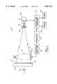
- FIG. 1 is an electro-optical schematic diagram that illustrates an apparatus for detecting stress and opaque variations in the sidewalls of a container in accordance with one presently preferred embodiment of the invention
- FIG. 2 is an electro-optical schematic diagram of an apparatus for detecting opaque and stress variations in the bottom of a container in accordance with another embodiment of the invention.
- FIG. 3 is a fragmentary side view of the inspection apparatus of FIG. 2.
- FIG. 1 illustrates an apparatus 10 for inspecting the sidewall of a container 14 in accordance with one presently preferred embodiment of the invention.
- a light source 16 comprises one or more lamps 18 that cooperate with a diffuser 20 to form a broad-area diffuse light source.
- Light energy is directed from diffuser 20 through a first polarizer lens 22 through the sidewall of container 14, and thence through a second polarizer lens 24 onto the sensor 26 of a camera 28.
- Sensor 26 preferably comprises a linear array CCD sensor for providing electrical signals to an information processor 30 as a function of the one-dimensional image of container 14 focused onto array 26.
- a blocking filter 32 is disposed so as partially to attenuate the light energy directed onto sensor 28.
- a conveyor 34 typically including a starwheel (not shown) and a slide plate 36, is so disposed and connected to a source of molded containers as to bring successive containers 14 into position at apparatus 10.
- Conveyor 34 may be of any suitable type, such as those shown in U.S. Pat. Nos. 4,230,219 and 4,378,493.
- Successive containers are held in fixed position and rotated by a device 38, such as a drive roller, about the central axis of the container.
- An encoder 40 is coupled to the container rotation mechanism to provide signals indicative of increments of container rotation. Such increments may comprise either fixed angular increments of rotation, or fixed time increments of rotation at a constant velocity.
- Information processor 30 is coupled to encoder 40 and to sensor 26 of camera 28 for scanning the sensor at increments of container rotation, and developing a two-dimensional electronic image of the container sidewall from differing angular positions with respect to the container axis.
- information processor 30 may be controlled to scan sensor 26 at substantially equal increments of time while container 14 is rotated at substantially constant angular velocity.
- Sensor 26 may comprise an area array sensor, which may be scanned at increments of container rotation to develop multiple two-dimensional images of the container sidewall. Each such image would consist of light and/or dark image signals against a grey background.
- the light energy emitted by lamp 18 through diffuser 20 comprises both visible and infrared light energy.
- the visible and infrared light energies need not necessarily cover the entire wavelength ranges noted above.
- Polarizers 22, 24 are at 90° orientation with respect to each other--i.e., crossed polarizers--and are constructed so as to be responsive to light energy within the visible wavelength range, while being substantially transparent to infrared light energy. Thus, incidence of light energy in the visible range onto sensor 26 is normally blocked by the crossed orientation of polarizers 22, 24.
- sensor 26 which is responsive to both visible and infrared energy, effectively combines the light energies from source 16 to create a normally gray background against which opaque variations appear dark and stress variations appear bright. These variations can be readily analyzed for size and type employing otherwise conventional image analysis techniques at information processor 30. See U.S. Pat. No. 4,601,395. Such information can be employed to send a reject signal 42 for removal of unsatisfactory containers from the line and/or to display image data at 44 to an operator. Exemplary techniques for scanning an area array sensor and developing two-dimensional electronic images of the container are disclosed in U.S. Pat. No. 4,958,223.
- the technique of the present invention thus provides improved detection of small opaque stressed stones, which will appear larger and be more easily detected because the stress pattern around the stone, as well as the stone itself, are visible to camera 28. Indeed, a stressed opaque stone will appear as a dark image of the stone surrounded by a bright image of the stressed area of the glass against a normally gray background.
- FIGS. 2 and 3 illustrate a second embodiment of the invention having particular utility for inspecting the bottom and heel portions of container 14. Elements that are identical or similar to those illustrated in FIG. 1 are identified by correspondingly identical reference numerals. Visible and infrared light energy is directed through a diffuser 20 and a polarizer lens 22 through an aperture 46 in slide plate 36, and then generally axially through the container bottom and heel. Camera 28, including area array sensor 26, is directed in cooperation with partial infrared filter 32 and polarizer lens 24 to receive light energy emanating from the mouth of container 14. Thus, sensor 26 cooperates with information processor 30 (FIG. 1) to develop multiple images of the container bottom, each consisting of a normally gray background against which stress variations appear as bright signals and opaque variations appear as dark signals.
- information processor 30 FIG. 1
- the light source including diffuser 20 and polarizer lens 22, may be configured as disclosed in U.S. Pat. No. 5,466,927, assigned to the assignee hereof, whereby camera 28 may be employed at increments of container rotation to detect refractive variations in the container bottom and heel.
- FIGS. 2 and 3 illustrate the camera receiving an image along the entire diameter of the container bottom and heel, the camera could be oriented and focused to view only a radius of the container bottom. The entire container bottom would be inspected as the bottle is rotated through one revolution.
- the method and apparatus of the invention may be implemented employing relatively inexpensive polarizer material responsive to light energy in the visible range, as distinguished from more expensive polarizer material responsive to light energy in the infrared range.
- the techniques of the invention may be readily employed in connection with both clear (flint) and colored (e.g., amber) glass.
- the method and system of the invention may be implemented at a single container inspection station, and employing a single light source and a single light sensor as described.
Abstract
Infrared and visible light energies are directed through a container onto a CCD camera that is responsive to both the visible and infrared light energy. Crossed polarizers are positioned on opposed sides of the container, and operate on the visible light energy in such a way as to block transmission of visible light to the camera in the absence of stress variations in the container, which alter polarization of the visible light energy traveling through the container. On the other hand, the polarizers have little or no effect on the infrared light energy, which creates a normally gray intensity of background light at the camera. In this way, incidence of visible light on the camera due to stress variations in the container appears as a bright signal against a normally gray background, while blockage of infrared light due to opaque variations in the container appears as a dark signal against the normally gray background.
Description
The present invention is directed to inspection of transparent containers for commercial variations that affect the optical properties of the containers, and more particularly to a method and apparatus for inspecting the containers for stress and non-stress variations in the container sidewall and bottom.
In the manufacture of transparent containers such as glass bottles and jugs, various types of anomalies can occur in the sidewalls, heels, bottoms, shoulders and/or necks of the containers. These anomalies, termed "commercial variations" in the art, can affect commercial acceptability of the containers. It has heretofore been proposed to employ electro-optical inspection techniques for detecting commercial variations that affect the optical properties of the containers. The basic principle is that a light source is positioned to direct light energy onto the container, and a camera is positioned to receive an image of the portion of the container illuminated by the light source. The light source may be of uniform intensity, or may be configured to have an intensity that varies across one dimension of the light source. Opaque and refractive commercial variations in the portion of the container illuminated by the light source are detected as a function of light intensity in the image of the illuminated container received and stored at the camera.
A problem is encountered in the manufacture of glass containers from recycled glass in that materials having different thermal expansion characteristics can become mixed in a single container. For example, it has been found that clear cookware, having very low thermal expansion characteristics, can become mixed with the glass for recycling. Any unmelted particles of the cookware that appear in the container create stress points on cooling that can fracture or become sites for later failures. Other inhomogeneities that can appear in the glass and cause stress variations include stones or bits of refractory material from the glass forehearth or spout. It is thus necessary to provide a method and system for detecting stress and opaque non-stress variations in the containers.
It has heretofore been proposed to employ crossed polarizers for detecting stress variations in the sidewalls of containers. Light energy directed through the crossed polarizers, and through a container positioned between the crossed polarizers, normally presents a dark field at the imaging camera in the absence of stress variations in the container sidewalls. However, a stress variation alters polarization of the light energy passing through the container sufficiently to present a bright spot at the camera against the otherwise dark background, indicative of the stress variation. See U.S. Pat. No. 4,026,656, assigned to the assignee hereof, which discusses such technology by way of background, and which proposes to employ infrared light energy and infrared polarization filters to reduce the background effects of ambient light.
It is a general object of the present invention to provide a method and apparatus for inspecting transparent glass articles, particularly glass containers, for commercial variations that affect optical characteristics of the containers. A more specific object of the present invention is to provide a method and apparatus of the described character that are particularly well suited for detecting both stress variations and opaque variations (stress and non-stress) in the container. Another object of the present invention is to provide a method and apparatus of the described character for detection of stress and opaque non-stress variations in containers at a single inspection station, with a single light source and a single light sensor. A further object of the present invention is to provide a method and apparatus of the described character that are economical to implement and reliable over an extended operating lifetime.
The present invention proposes to direct both infrared and visible light energy through a container onto a camera that is responsive to both visible and infrared light energy. Crossed polarizers are positioned on opposed sides of the container, and operate on the visible light energy in such a way as to block transmission of visible light to the camera in the absence of stress variations in the container, which alter polarization of the visible light energy traveling through the container. On the other hand, the polarizers have little or no effect on the infrared light energy, which creates a normally gray intensity of background light at the camera. In this way, incidence of visible light on the camera due to stress variations in the container appears as bright signals against a normally gray background, while blockage of infrared light due to opaque variations in the container appears as dark signals against the normally gray background.
In accordance with one aspect of the present invention, there is therefore provided a method of inspecting a container for commercial variations that affect optical characteristics of the containers, in which light energy is directed onto the container in such a way that a first wavelength of light energy (e.g., polarized visible light energy) is responsive to a first type of commercial variation in the container (e.g., stress variations), and a second wavelength of the light energy different from the first wavelength (e.g., infrared light energy) is responsive to a second type of commercial variation different from the first type (e.g., opaque variations). The light energy from the container is directed onto light sensing means, and commercial variations are detected as a function of light energy at the first and second wavelengths incident on the light sensing means. The light sensing means preferably takes the form of a single light sensor responsive to light energy at both of the first and second wavelengths, which preferably are directed onto the container and thence onto the sensor simultaneously. Light energy received at the sensor at the first wavelength is compared to light energy received at the second wavelength, preferably by forming an image of light energy at the sensor at the first wavelength against a background of energy at the sensor at the second wavelength. The light sensor in the preferred embodiments of the invention comprises a CCD array sensor that is scanned at increments of container rotation to provide a two-dimensional image of the inspected portion of the container that consists of light energy received at the first wavelength against a background of light energy received at the second wavelength.
In the preferred embodiments of the invention, the light energy at the first wavelength comprises polarized visible light energy responsive to stress variations in the container, while light energy at the second wavelength comprises infrared light energy responsive to opaque variations at the container. The terms "visible" and "infrared" light energies are used in their conventional senses. Visible light energy is light energy within the wavelength range of about 0.4 to 0.7 or 0.8 micrometers. Infrared light energy, which includes near-infrared light energy in accordance with the present invention, has a wavelength within the range of about 0.7 to 300 micrometers. Glass, however, becomes opaque at about 5 micrometers, which establishes an effective upper limit in such applications. The presently preferred silicon camera is sensitive up to about 1.1 micrometers. Light energy in both wavelength ranges is generated in the preferred embodiments of the invention by a broad area diffuse light source, and is incident on a CCD area array sensor that is responsive to both visible and infrared light energy.
Apparatus for detection of stress variations and opaque variations in glass articles such as containers in accordance with another aspect of the present invention comprises a light sensor for producing electrical signals responsive to light energy incident thereon in both the visible and infrared ranges. Infrared light energy is directed through a container onto the light sensor in such a way as to create at the light sensor a normally gray background, and such that opaque variations in the container appear as dark signals against the gray background. Visible light energy is directed through crossed polarizers disposed on opposite sides of the container and onto the light sensor in such a way that stress variations in the container appear as bright signals against the gray background at the sensor. The stress and opaque variations are thus detected as a function of the bright and dark signals against the gray background at the sensor.
The invention, together with additional objects, features and advantages thereof, will be best understood from the following description, the appended claims and the accompanying drawings in which:
FIG. 1 is an electro-optical schematic diagram that illustrates an apparatus for detecting stress and opaque variations in the sidewalls of a container in accordance with one presently preferred embodiment of the invention;
FIG. 2 is an electro-optical schematic diagram of an apparatus for detecting opaque and stress variations in the bottom of a container in accordance with another embodiment of the invention; and
FIG. 3 is a fragmentary side view of the inspection apparatus of FIG. 2.
FIG. 1 illustrates an apparatus 10 for inspecting the sidewall of a container 14 in accordance with one presently preferred embodiment of the invention. A light source 16 comprises one or more lamps 18 that cooperate with a diffuser 20 to form a broad-area diffuse light source. Light energy is directed from diffuser 20 through a first polarizer lens 22 through the sidewall of container 14, and thence through a second polarizer lens 24 onto the sensor 26 of a camera 28. Sensor 26 preferably comprises a linear array CCD sensor for providing electrical signals to an information processor 30 as a function of the one-dimensional image of container 14 focused onto array 26. A blocking filter 32 is disposed so as partially to attenuate the light energy directed onto sensor 28.
A conveyor 34, typically including a starwheel (not shown) and a slide plate 36, is so disposed and connected to a source of molded containers as to bring successive containers 14 into position at apparatus 10. Conveyor 34 may be of any suitable type, such as those shown in U.S. Pat. Nos. 4,230,219 and 4,378,493. Successive containers are held in fixed position and rotated by a device 38, such as a drive roller, about the central axis of the container. An encoder 40 is coupled to the container rotation mechanism to provide signals indicative of increments of container rotation. Such increments may comprise either fixed angular increments of rotation, or fixed time increments of rotation at a constant velocity. Information processor 30 is coupled to encoder 40 and to sensor 26 of camera 28 for scanning the sensor at increments of container rotation, and developing a two-dimensional electronic image of the container sidewall from differing angular positions with respect to the container axis. As an alternative to use of an encoder 40, information processor 30 may be controlled to scan sensor 26 at substantially equal increments of time while container 14 is rotated at substantially constant angular velocity. Sensor 26 may comprise an area array sensor, which may be scanned at increments of container rotation to develop multiple two-dimensional images of the container sidewall. Each such image would consist of light and/or dark image signals against a grey background.
In accordance with the present invention, the light energy emitted by lamp 18 through diffuser 20 comprises both visible and infrared light energy. (The visible and infrared light energies need not necessarily cover the entire wavelength ranges noted above.) Polarizers 22, 24 are at 90° orientation with respect to each other--i.e., crossed polarizers--and are constructed so as to be responsive to light energy within the visible wavelength range, while being substantially transparent to infrared light energy. Thus, incidence of light energy in the visible range onto sensor 26 is normally blocked by the crossed orientation of polarizers 22, 24. However, birefringence in the sidewall of container 14 caused by stress variations, such as stressed stones or knots, alters the angle of polarization of the light passing through the stress region, thereby producing a bright signal at sensor 26 against what would otherwise be the normally dark background of the visible light energy. In the meantime, the infrared light energy passes directly through the sidewalls of containe unless affected by opaque variations such as stress or non-stress stones. Filter 32 as responsive to light energy in the infrared range partially to attenuate such light energy, and thereby to create at sensor 26 a normally gray background, against which visible light caused by stress variations in the container sidewall appear as bright signals and infrared light blocked by opaque variations in the container sidewall appear as dark signals.
Thus, sensor 26, which is responsive to both visible and infrared energy, effectively combines the light energies from source 16 to create a normally gray background against which opaque variations appear dark and stress variations appear bright. These variations can be readily analyzed for size and type employing otherwise conventional image analysis techniques at information processor 30. See U.S. Pat. No. 4,601,395. Such information can be employed to send a reject signal 42 for removal of unsatisfactory containers from the line and/or to display image data at 44 to an operator. Exemplary techniques for scanning an area array sensor and developing two-dimensional electronic images of the container are disclosed in U.S. Pat. No. 4,958,223. The technique of the present invention thus provides improved detection of small opaque stressed stones, which will appear larger and be more easily detected because the stress pattern around the stone, as well as the stone itself, are visible to camera 28. Indeed, a stressed opaque stone will appear as a dark image of the stone surrounded by a bright image of the stressed area of the glass against a normally gray background.
FIGS. 2 and 3 illustrate a second embodiment of the invention having particular utility for inspecting the bottom and heel portions of container 14. Elements that are identical or similar to those illustrated in FIG. 1 are identified by correspondingly identical reference numerals. Visible and infrared light energy is directed through a diffuser 20 and a polarizer lens 22 through an aperture 46 in slide plate 36, and then generally axially through the container bottom and heel. Camera 28, including area array sensor 26, is directed in cooperation with partial infrared filter 32 and polarizer lens 24 to receive light energy emanating from the mouth of container 14. Thus, sensor 26 cooperates with information processor 30 (FIG. 1) to develop multiple images of the container bottom, each consisting of a normally gray background against which stress variations appear as bright signals and opaque variations appear as dark signals. The light source, including diffuser 20 and polarizer lens 22, may be configured as disclosed in U.S. Pat. No. 5,466,927, assigned to the assignee hereof, whereby camera 28 may be employed at increments of container rotation to detect refractive variations in the container bottom and heel. Furthermore, although FIGS. 2 and 3 illustrate the camera receiving an image along the entire diameter of the container bottom and heel, the camera could be oriented and focused to view only a radius of the container bottom. The entire container bottom would be inspected as the bottle is rotated through one revolution.
It will also be appreciated that the techniques of the present invention for detecting opaque and stress variations may be employed in combination with other techniques for detecting refractive variations, for example, such as disclosed in above-noted U.S. Pat. No. 5,466,927 for detection of refractive characteristics in the container bottom and heel, and as disclosed in U.S. Pat. No. 4,601,395 for detection of refractive variations in the container sidewall.
There have thus been provided in accordance with the present invention a method and apparatus for inspecting glass articles such as containers for commercial variations that affect the optical characteristics of the containers, particularly stress variations and opaque variations in the containers. The method and apparatus of the invention may be implemented employing relatively inexpensive polarizer material responsive to light energy in the visible range, as distinguished from more expensive polarizer material responsive to light energy in the infrared range. The techniques of the invention may be readily employed in connection with both clear (flint) and colored (e.g., amber) glass. The method and system of the invention may be implemented at a single container inspection station, and employing a single light source and a single light sensor as described.
Claims (23)
1. A method of inspecting containers for commercial variations that affect optical characteristics of the containers, which comprises the steps of:
(a) directing light energy onto a container in such a way that a first wavelength of the light energy is responsive to a first type of commercial variation in the container and a second wavelength of the light energy different from said first wavelength is responsive to a second type of commercial variation different from said first type,
(b) detecting light energy from the container onto light sensing means, and
(c) detecting commercial variations of said first and second types at the container as a function of a comparison between light energies at said first and second wavelengths incident on said light sensing means by forming an image at said light sensing means of light energy at said first wavelength against a background of energy at said second wavelength.
2. The method set forth in claim 1 comprising the additional step of: (d) providing said light sensing means in the form of a single sensor responsive to light energy at both of said first and second wavelengths.
3. The method set forth in claim 2 wherein said light energies at said first and second wavelengths are incident simultaneously on said single sensor.
4. The method set forth in claim 1 wherein said sensing means comprises an area array sensor for providing a two-dimensional image that consists of light energy received at said first wavelength against a background of light energy received at said second wavelength.
5. The method set forth in claim 4 wherein said light energy at said first wavelength comprises visible light energy, and said light energy at said second wavelength comprises infrared light energy.
6. The method set forth in claim 5 wherein said visible light energy comprises polarized light energy.
7. The method set forth in claim 5 wherein said visible light energy is within the wavelength range of about 0.4 to 0.7 micrometers, and said infrared light energy is within the wavelength range of about 0.7 to 300 micrometers.
8. The method set forth in claim 7 wherein said containers are glass containers, and wherein said infrared energy is in the range of about 0.7 to 5 micrometers.
9. The method set forth in claim 8 wherein said infrared energy is in the range of about 0.7 to 1.1 micrometers.
10. The method set forth in claim 1 comprising the additional steps of:
(d) polarizing said energy at one of said first and second wavelengths in such a way that only light energy at said one wavelength that passes through a stress variation at the containers is incident on said sensing means, and
(e) partially attenuating light energy at the other of said first and second wavelengths.
11. The method set forth in claim 1 comprising the additional steps of:
(d) rotating the container about its central axis, and
(e) performing said step (c) at increments of container rotation.
12. The method set forth in claim 1 for inspecting a container sidewall wherein said steps (a) and (b) comprise the step of directing said light energies simultaneously onto the container sidewall.
13. The method set forth in claim 1 for inspecting a container bottom wherein said steps (a) and (b) comprise the step of directing said light energies simultaneously into the container bottom.
14. The method set forth in claim 1 comprising the additional step of: (d) detecting commercial variations of a third type different from said first and second types as a function of at least one of said light energies at said sensing means.
15. Apparatus for detection of stress variations and opaque variations in containers, which comprises:
light sensing means for producing electrical signals responsive to light energy incident thereon in visible and infrared ranges,
first means for directing infrared light energy through a container onto said light sensing means in such a way as to create at said light sensing means a normally gray background, and such that opaque variations in the container appear as dark signals against said gray background,
second means, including crossed polarizers disposed on opposite sides of the container, for directing visible light energy through the container and onto said light sensing means in such a way that stress variations in the container appear as bright signals against the gray background at said light sensing means, and
means coupled to said light sensing means for detecting such stress and opaque variations as a function of said bright and dark signals against said gray background.
16. The apparatus set forth in claim 15 wherein said first and second means comprise a single light source for directing said visible and infrared light energies through the container and onto said light sensing means simultaneously.
17. The apparatus set forth in claim 16 wherein said light sensing means comprises a single light sensor.
18. The apparatus set forth in claim 17 wherein said single light sensor comprises an array sensor for receiving an image of the container that includes said light and dark signals against said gray background.
19. The apparatus set forth in claim 18 further comprising means for rotating the container about its axis, and means for scanning said light sensor at increments of container rotation.
20. A method of inspecting transparent glass articles for stress variations and opaque variations that comprises the steps of:
(a) directing light energies at first and second wavelength ranges through an article simultaneously onto a single light sensor,
(b) partially attenuating one of said light energy wavelength ranges so as to create a gray background at said sensor against which an opaque variation at the article appears as a dark image against said gray background,
(c) polarizing the other of said wavelength ranges such that a stress variation at the article appears as a light image against said gray background, and
(d) detecting stress and opaque variations in the article as a function of said light and dark images.
21. The method set forth in claim 18 wherein said sensor comprises a CCD sensor that receives an image consisting of said light and dark images against said gray background.
22. The method set forth in claim 21 wherein said step (a) comprises the step of generating light energy at both of said wavelength ranges from a single light source.
23. The method set forth in claim 22 wherein said single light source comprises a broad area diffuse light source.
Priority Applications (21)
| Application Number | Priority Date | Filing Date | Title |
|---|---|---|---|
| US08/997,987 US6067155A (en) | 1997-12-24 | 1997-12-24 | Optical inspection of transparent containers using infrared and polarized visible light |
| ZA9811514A ZA9811514B (en) | 1997-12-24 | 1998-12-15 | Optical inspection of tranparent containers using infrared and polarized visible light |
| CA002256192A CA2256192C (en) | 1997-12-24 | 1998-12-15 | Optical inspection of transparent containers using infrared and polarized visible light |
| HU9802908A HU226346B1 (en) | 1997-12-24 | 1998-12-15 | Optical inspection of transparent containers using infrared and polarized visible light |
| CO98075229A CO4810350A1 (en) | 1997-12-24 | 1998-12-17 | METHOD AND APPARATUS FOR THE INSPECTION OF TRANSPARENT CONTAINERS USING INFRARED AND VISIBLE POLARIZED LIGHT |
| DK98124071T DK0926486T3 (en) | 1997-12-24 | 1998-12-18 | Optical inspection of transparent containers using infrared and polarized visible light |
| EP98124071A EP0926486B1 (en) | 1997-12-24 | 1998-12-18 | Optical inspection of transparent containers using infrared and polarized visible light |
| DE69807311T DE69807311T2 (en) | 1997-12-24 | 1998-12-18 | Optical inspection of transparent containers using infrared and polarized visible light |
| ES98124071T ES2182213T3 (en) | 1997-12-24 | 1998-12-18 | OPTICAL INSPECTION OF TRANSPARENT CONTAINERS USING INFRARED LIGHT AND POLARIZED VISIBLE LIGHT. |
| PT98124071T PT926486E (en) | 1997-12-24 | 1998-12-18 | OPTICAL INSPECTION OF TRANSPARENT CONTAINERS USING INFRARED LIGHT AND POLARIZED VISIBLE LIGHT |
| AT98124071T ATE222652T1 (en) | 1997-12-24 | 1998-12-18 | OPTICAL INSPECTION OF TRANSPARENT CONTAINER USING INFRARED AND POLARIZED VISIBLE LIGHT |
| PE1998001258A PE20000195A1 (en) | 1997-12-24 | 1998-12-21 | OPTICAL INSPECTION OF TRANSPARENT CONTAINERS USING VISIBLE INFRARED AND POLARIZED LIGHT |
| AU97244/98A AU746288B2 (en) | 1997-12-24 | 1998-12-21 | Optical inspection of transparent containers using infrared and polarized visible light |
| CZ0426898A CZ298062B6 (en) | 1997-12-24 | 1998-12-21 | Method of detection of commercial variations and opaque variations in containers and apparatus for making the same |
| PL98330488A PL189617B1 (en) | 1997-12-24 | 1998-12-22 | Method of and apparatus for inspecting containers by means of visible radiation |
| BRPI9805532-1A BR9805532B1 (en) | 1997-12-24 | 1998-12-23 | optical inspection of transparent containers using visible, infrared and polarized lighting. |
| RU98124075/28A RU2224241C2 (en) | 1997-12-24 | 1998-12-23 | Method testing clear glass containers for presence of deviations of stresses and degree of transparency and facility for its implementation |
| ARP980106676A AR014180A1 (en) | 1997-12-24 | 1998-12-23 | METHOD FOR INSPECTING PACKAGING TO DETECT COMMERCIAL VARIATIONS, DEVICE FOR DETECTION OF VARIATIONS OF EFFORT AND OPTIONAL VARIATIONS IN PACKAGING, AND METHOD FOR INSPECTING TRANSPARENT GLASS ITEMS TO DETECT VARIATIONS OF VARIATION AND VARIATIONS |
| EE9800457A EE03627B1 (en) | 1997-12-24 | 1998-12-23 | Method and apparatus for detecting voltage and non-voltage defects affecting the optical properties of transparent vessels |
| CN98111684A CN1114100C (en) | 1997-12-24 | 1998-12-24 | Method and apparatus for optical inspection of transparent containers using infrared and polarized visible light |
| JP36792298A JP4302804B2 (en) | 1997-12-24 | 1998-12-24 | Optical inspection of transparent containers using infrared light and polarized visible light |
Applications Claiming Priority (1)
| Application Number | Priority Date | Filing Date | Title |
|---|---|---|---|
| US08/997,987 US6067155A (en) | 1997-12-24 | 1997-12-24 | Optical inspection of transparent containers using infrared and polarized visible light |
Publications (1)
| Publication Number | Publication Date |
|---|---|
| US6067155A true US6067155A (en) | 2000-05-23 |
Family
ID=25544635
Family Applications (1)
| Application Number | Title | Priority Date | Filing Date |
|---|---|---|---|
| US08/997,987 Expired - Lifetime US6067155A (en) | 1997-12-24 | 1997-12-24 | Optical inspection of transparent containers using infrared and polarized visible light |
Country Status (21)
| Country | Link |
|---|---|
| US (1) | US6067155A (en) |
| EP (1) | EP0926486B1 (en) |
| JP (1) | JP4302804B2 (en) |
| CN (1) | CN1114100C (en) |
| AR (1) | AR014180A1 (en) |
| AT (1) | ATE222652T1 (en) |
| AU (1) | AU746288B2 (en) |
| BR (1) | BR9805532B1 (en) |
| CA (1) | CA2256192C (en) |
| CO (1) | CO4810350A1 (en) |
| CZ (1) | CZ298062B6 (en) |
| DE (1) | DE69807311T2 (en) |
| DK (1) | DK0926486T3 (en) |
| EE (1) | EE03627B1 (en) |
| ES (1) | ES2182213T3 (en) |
| HU (1) | HU226346B1 (en) |
| PE (1) | PE20000195A1 (en) |
| PL (1) | PL189617B1 (en) |
| PT (1) | PT926486E (en) |
| RU (1) | RU2224241C2 (en) |
| ZA (1) | ZA9811514B (en) |
Cited By (43)
| Publication number | Priority date | Publication date | Assignee | Title |
|---|---|---|---|---|
| WO2002025251A2 (en) * | 2000-09-19 | 2002-03-28 | Eastman Chemical Company | Device and method for the optical inspection, assessment, and control of colored plastic articles and/or container contents |
| US20020154809A1 (en) * | 2000-02-03 | 2002-10-24 | Takahiro Yamagishi | Method and device for imaging liquid-filled container |
| US6504606B2 (en) * | 2000-10-02 | 2003-01-07 | Scan Technology Co., Ltd. | Integrated soft bag inspection system |
| US20030012421A1 (en) * | 2000-12-30 | 2003-01-16 | Lothar Werzinger | Inspection method and device |
| US20030029946A1 (en) * | 2001-05-18 | 2003-02-13 | Lieber Kenneth Jonh | Control feedback system and method for bulk material industrial processes using automated object or particle analysis |
| US20030035103A1 (en) * | 2000-05-31 | 2003-02-20 | Lothar Werzinger | Method and device for inspecting transparent containers |
| US6532064B1 (en) * | 2001-10-16 | 2003-03-11 | Baader-Canpolar Inc. | Automatic inspection apparatus and method for simultaneous detection of anomalies in a 3-dimensional translucent object |
| US6545427B1 (en) * | 1999-11-16 | 2003-04-08 | Patent-Treuhand-Gesellschaft für elektrische Glühlampen mbH | Discharge lamp having an improved temperature homogeneity |
| US6618495B1 (en) * | 1998-02-19 | 2003-09-09 | Emhart Glass, S.A. | Container inspection machine |
| US20030169424A1 (en) * | 2002-03-09 | 2003-09-11 | Kimberly-Clark Worldwide, Inc. | Infrared detection of composite article components |
| US20030168614A1 (en) * | 2002-03-09 | 2003-09-11 | Kimberly-Clark Worldwide, Inc. | Apparatus and method for inspecting pre-fastened articles |
| US20030169433A1 (en) * | 2002-03-09 | 2003-09-11 | Kimberly-Clark Worldwide, Inc. | Process for the detection of marked components of a composite article using infrared blockers |
| US6629010B2 (en) | 2001-05-18 | 2003-09-30 | Advanced Vision Particle Measurement, Inc. | Control feedback system and method for bulk material industrial processes using automated object or particle analysis |
| US20030214649A1 (en) * | 2002-05-14 | 2003-11-20 | Scan Technology Co., Ltd. | Inspecting apparatus for foreign matter |
| US20040022426A1 (en) * | 2002-07-31 | 2004-02-05 | Kimberly-Clark Worldwide, Inc. | Apparatus and method for inspecting articles |
| US6900450B2 (en) | 2002-03-09 | 2005-05-31 | Kimberly-Clark Worldwide, Inc. | Method and apparatus for inferring item position based on multiple data |
| US20050134843A1 (en) * | 2003-12-19 | 2005-06-23 | International Business Machines Corporation | Detection of impurities in cylindrically shaped transparent media |
| US6911653B2 (en) | 2002-04-26 | 2005-06-28 | Scan Technology Co., Ltd. | Inspecting method and apparatus for foreign matter |
| US6919965B2 (en) | 2002-03-09 | 2005-07-19 | Kimberly-Clark Worldwide, Inc. | Apparatus and method for making and inspecting pre-fastened articles |
| NL1025332C2 (en) * | 2004-01-27 | 2005-08-02 | Heineken Tech Services | Device and method for detecting contamination in a container. |
| US7148961B1 (en) | 2004-11-10 | 2006-12-12 | Owens-Brockway Glass Container Inc. | Container sidewall inspection |
| US20070058160A1 (en) * | 2005-09-13 | 2007-03-15 | Instrument Technology Research Center | Image inspection method by polarized compensation for deformation of lens |
| US7491922B1 (en) | 2005-04-25 | 2009-02-17 | Science Research Laboratory, Inc. | System and methods for image acquisition |
| US20090154789A1 (en) * | 2007-12-17 | 2009-06-18 | Gradience Imaging, Inc. | System and method for detecting optical defects |
| US20090294674A1 (en) * | 2005-04-06 | 2009-12-03 | Guillaume Bathelet | Method and Device for Eliminating Parasite Reflections During Inspection of Translucent or Transparent Hollow Objects |
| US7767951B1 (en) | 2005-04-25 | 2010-08-03 | Science Research Laboratory, Inc. | Systems and methods for image acquisition |
| US8345239B1 (en) * | 2008-08-04 | 2013-01-01 | Fluid Imaging Technologies, Inc. | System and method for monitoring birefringent particles in a fluid |
| CN101413936B (en) * | 2007-10-16 | 2013-05-15 | 中国建材检验认证集团股份有限公司 | Method for detecting automatic detonation hidden danger of glass curtain wall |
| WO2014070364A1 (en) * | 2012-11-01 | 2014-05-08 | Owens-Brockway Glass Container Inc. | Inspectable black glass containers |
| US8994945B2 (en) | 2011-10-27 | 2015-03-31 | Fluid Imaging Technologies, Inc. | Method of treatment analysis with particle imaging |
| US9316539B1 (en) * | 2015-03-10 | 2016-04-19 | LightHaus Photonics Pte. Ltd. | Compact spectrometer |
| US9327079B2 (en) | 2014-10-06 | 2016-05-03 | ZebraSci, Inc | Syringe barrel lubricant coverage quality control |
| US9366617B1 (en) * | 2015-07-10 | 2016-06-14 | David E. Doggett | Self-stirring container |
| CN106017340A (en) * | 2016-07-06 | 2016-10-12 | 北京大恒图像视觉有限公司 | Light-transmitting container wall thickness detection apparatus and method based on machine vision |
| US9677988B1 (en) | 2015-07-10 | 2017-06-13 | David E. Doggett | Integrating radiation collection and detection apparatus |
| US9983115B2 (en) | 2015-09-21 | 2018-05-29 | Fluid Imaging Technologies, Inc. | System and method for monitoring particles in a fluid using ratiometric cytometry |
| US20190049390A1 (en) * | 2016-02-03 | 2019-02-14 | Glaxosmithkline Biologicals S.A. | Novel Device |
| US20190164269A1 (en) * | 2016-08-01 | 2019-05-30 | Schott Schweiz Ag | Method and device for optical examination of transparent bodies |
| US10422755B2 (en) | 2016-12-07 | 2019-09-24 | Applied Vision Corporation | Identifying defects in transparent containers |
| US20210056681A1 (en) * | 2018-05-03 | 2021-02-25 | Inspekto A.M.V. Ltd. | System and method for visual production line inspection of different production items |
| US10989522B2 (en) * | 2019-03-11 | 2021-04-27 | Robex, LLC | Glass product stress evaluation system and method |
| US20210372778A1 (en) * | 2017-11-24 | 2021-12-02 | Sony Corporation | Detection apparatus and method of producing electronic apparatus |
| US11306016B2 (en) * | 2012-12-13 | 2022-04-19 | Centrum Voor Techishe Informatica B.V. | Method of producing glass products from glass product material and an assembly for performing said method |
Families Citing this family (31)
| Publication number | Priority date | Publication date | Assignee | Title |
|---|---|---|---|---|
| US6061125A (en) * | 1998-01-27 | 2000-05-09 | Insight Control Systems International | Dual illumination apparatus for container inspection |
| JP2001221747A (en) | 2000-02-03 | 2001-08-17 | Suntory Ltd | Imaging method of liquid filling container and device |
| DE10164058B4 (en) * | 2000-12-30 | 2008-06-12 | Krones Ag | inspection device |
| DE60223956T3 (en) † | 2001-03-14 | 2011-05-19 | Hitachi Information & Control Solutions, Ltd., Hitachi | Examination device and system for the examination of foreign objects in containers filled with liquid |
| DE20108131U1 (en) * | 2001-05-14 | 2002-06-20 | Krones Ag | Device for recognizing the material of vessels |
| US20040263838A1 (en) * | 2003-06-30 | 2004-12-30 | Diehr Richard D. | Container inspection machine |
| US6795176B1 (en) * | 2003-06-30 | 2004-09-21 | Emhart Glass S.A. | Container inspection machine |
| EP1598662A1 (en) * | 2004-05-17 | 2005-11-23 | Total Petrochemicals Research Feluy | A method for quantifying the optical properties of moulded objects |
| DE202006019722U1 (en) * | 2006-12-29 | 2008-04-30 | Krones Ag | Device for treating vessels |
| DE102008015411A1 (en) * | 2008-03-20 | 2009-10-01 | Khs Ag | Transport system for bottles or similar containers and apparatus for treating bottles or similar containers |
| US8429989B2 (en) * | 2008-10-18 | 2013-04-30 | Emhart Glass S.A. | Modular apparatus and method for rotating glass containers and the like |
| EP2253948B1 (en) * | 2009-05-22 | 2013-01-09 | Dr. Schenk GmbH Industriemesstechnik | Device and method for optical examination of an object |
| EP2282186B1 (en) * | 2009-08-05 | 2015-09-09 | Emhart Glass S.A. | Glass container stress measurement using fluorescence |
| EP2381246A1 (en) * | 2010-04-26 | 2011-10-26 | Becton Dickinson France | Device, kit and method for inspection of an article |
| DE102010062922A1 (en) * | 2010-12-13 | 2012-06-14 | Krones Aktiengesellschaft | Inspection carrier for containers |
| DE102011004584A1 (en) * | 2011-02-23 | 2012-08-23 | Krones Aktiengesellschaft | Method and apparatus for detecting bubbles and / or wrinkles on labeled containers |
| CN102226771B (en) * | 2011-03-25 | 2012-11-28 | 宁波大学 | Device for detecting internal defects and residual stress of infrared glass and detection method |
| FR2977939B1 (en) | 2011-07-11 | 2013-08-09 | Edixia | METHOD FOR ACQUIRING MULTIPLE IMAGES OF THE SAME OBJECT USING A SINGLE LINEAR CAMERA |
| CN102323275B (en) * | 2011-08-10 | 2013-06-05 | 宁波大学 | Imaging detection device of infrared chalcogenide glass internal macroscopic defect |
| KR20140132773A (en) * | 2012-04-23 | 2014-11-18 | 쌩-고벵 글래스 프랑스 | Method and arrangement for measuring blowing structures of a prestressed disc |
| CN102914547B (en) * | 2012-10-09 | 2015-04-22 | 上海交通大学 | System and method for automatically detecting impurities in bottled liquid |
| CN102963717B (en) * | 2012-12-07 | 2015-08-12 | 安丘耀发机器有限公司 | The pneumatic conjunction fork device of a kind of photoelectricity joint control |
| CN105301010A (en) * | 2015-09-23 | 2016-02-03 | 广东暨通信息发展有限公司 | Bottle body defect detection device for glass bottle |
| CN107957395B (en) * | 2016-10-17 | 2020-07-03 | 山东赛蒙斯生物技术有限公司 | Detection device for foreign matter in transparent/translucent product |
| CN110431405B (en) * | 2017-02-06 | 2022-06-14 | 东洋玻璃株式会社 | Glass bottle inspection device |
| DE102017223347A1 (en) * | 2017-12-20 | 2019-06-27 | Krones Ag | Transmitted-light inspection device and transmitted-light inspection method for sidewall inspection of containers |
| DE102019208296A1 (en) | 2019-06-06 | 2020-12-10 | Krones Ag | Method and device for the optical inspection of containers |
| DE102019208299A1 (en) | 2019-06-06 | 2020-12-10 | Krones Ag | Method and device for the optical inspection of containers |
| DE102019208295A1 (en) | 2019-06-06 | 2020-12-10 | Krones Ag | Method and device for the optical inspection of containers |
| FR3131634B1 (en) * | 2021-12-30 | 2024-01-05 | Tiama | Method and device for inspecting hot glass containers to identify defects |
| FR3133606A1 (en) * | 2022-03-21 | 2023-09-22 | Michael Paetzold | Device for reading an identifier affixed to a bottle moving on a conveyor system, module and bottling line integrating said device |
Citations (18)
| Publication number | Priority date | Publication date | Assignee | Title |
|---|---|---|---|---|
| US1681991A (en) * | 1926-11-20 | 1928-08-28 | Corning Glass Works | Method of detecting and measuring strains |
| US1934187A (en) * | 1930-12-26 | 1933-11-07 | Roy S Glasgow | Electrical means for testing translucent materials |
| US3963348A (en) * | 1972-07-14 | 1976-06-15 | Yamamura Glass Kabushiki Kaisha | Device for detecting strain and foreign matters in glass container by a non-storage type pickup tube |
| FR2323143A1 (en) * | 1975-09-02 | 1977-04-01 | Owens Illinois Inc | DETECTOR OF SOLID INCLUSIONS IN THE WALLS OF GLASS CONTAINERS |
| FR2437616A1 (en) * | 1978-09-29 | 1980-04-25 | Kirin Brewery | APPARATUS FOR DETECTING THE PRESENCE OF FOREIGN BODIES ON OBJECTS, SUCH AS BOTTLES |
| US4283145A (en) * | 1979-02-13 | 1981-08-11 | Kirin Beer Kabushiki Kaisha | Optical system for the detection of flaws in bottles or the like |
| US4547067A (en) * | 1982-12-21 | 1985-10-15 | Yamamura Glass Kabushiki Kaisha | Apparatus for detecting faults in transparent objects |
| DE3705143A1 (en) * | 1986-03-10 | 1987-09-17 | Uevegipari Muevek | METHOD AND DEVICE FOR INTEGRAL OPTICAL CHECKING OF HARMFUL MECHANICAL TENSIONS IN THE BOTTOM PART OF BOTTLES AND HOLLOW GLASSES |
| US4902137A (en) * | 1987-02-04 | 1990-02-20 | Harro Hofliger Verpackungsmasghinen GmbH | Method and apparatus for the determination of foreign bodies in fluids |
| DE3840005A1 (en) * | 1988-11-26 | 1990-05-31 | Komi Koppelberg & Migl Kg Masc | Method and device for testing hollow glass bodies for contained inclusions |
| US5095204A (en) * | 1990-08-30 | 1992-03-10 | Ball Corporation | Machine vision inspection system and method for transparent containers |
| US5141110A (en) * | 1990-02-09 | 1992-08-25 | Hoover Universal, Inc. | Method for sorting plastic articles |
| US5444237A (en) * | 1993-04-12 | 1995-08-22 | Toyo Glass Company Limited | Apparatus for inspecting a bottom border portion of transparent glass vessel for a foreign article |
| US5444535A (en) * | 1993-08-09 | 1995-08-22 | Labatt Brewing Company Limited | High signal-to-noise optical apparatus and method for glass bottle thread damage detection |
| US5466927A (en) * | 1994-04-08 | 1995-11-14 | Owens-Brockway Glass Container Inc. | Inspection of translucent containers |
| US5502559A (en) * | 1993-11-01 | 1996-03-26 | Environmental Products Corporation | Apparatus and method for detection of material used in construction of containers and color of same |
| US5536935A (en) * | 1994-02-17 | 1996-07-16 | Thermedics Detection, Inc. | Detection of foaming contaminants in containers using image processing |
| WO1997046329A1 (en) * | 1996-06-04 | 1997-12-11 | Inex, Inc. Doing Business As Inex Vision Systems, Inc. | System and method for stress detection in a molded container |
Family Cites Families (1)
| Publication number | Priority date | Publication date | Assignee | Title |
|---|---|---|---|---|
| US4258223A (en) * | 1978-08-08 | 1981-03-24 | Cities Service Company | Process for the preparation of tertiary butyl alcohol |
-
1997
- 1997-12-24 US US08/997,987 patent/US6067155A/en not_active Expired - Lifetime
-
1998
- 1998-12-15 CA CA002256192A patent/CA2256192C/en not_active Expired - Fee Related
- 1998-12-15 ZA ZA9811514A patent/ZA9811514B/en unknown
- 1998-12-15 HU HU9802908A patent/HU226346B1/en not_active IP Right Cessation
- 1998-12-17 CO CO98075229A patent/CO4810350A1/en unknown
- 1998-12-18 EP EP98124071A patent/EP0926486B1/en not_active Expired - Lifetime
- 1998-12-18 DK DK98124071T patent/DK0926486T3/en active
- 1998-12-18 ES ES98124071T patent/ES2182213T3/en not_active Expired - Lifetime
- 1998-12-18 AT AT98124071T patent/ATE222652T1/en active
- 1998-12-18 DE DE69807311T patent/DE69807311T2/en not_active Expired - Lifetime
- 1998-12-18 PT PT98124071T patent/PT926486E/en unknown
- 1998-12-21 PE PE1998001258A patent/PE20000195A1/en not_active Application Discontinuation
- 1998-12-21 AU AU97244/98A patent/AU746288B2/en not_active Ceased
- 1998-12-21 CZ CZ0426898A patent/CZ298062B6/en not_active IP Right Cessation
- 1998-12-22 PL PL98330488A patent/PL189617B1/en unknown
- 1998-12-23 AR ARP980106676A patent/AR014180A1/en active IP Right Grant
- 1998-12-23 BR BRPI9805532-1A patent/BR9805532B1/en not_active IP Right Cessation
- 1998-12-23 RU RU98124075/28A patent/RU2224241C2/en not_active IP Right Cessation
- 1998-12-23 EE EE9800457A patent/EE03627B1/en not_active IP Right Cessation
- 1998-12-24 CN CN98111684A patent/CN1114100C/en not_active Expired - Fee Related
- 1998-12-24 JP JP36792298A patent/JP4302804B2/en not_active Expired - Fee Related
Patent Citations (20)
| Publication number | Priority date | Publication date | Assignee | Title |
|---|---|---|---|---|
| US1681991A (en) * | 1926-11-20 | 1928-08-28 | Corning Glass Works | Method of detecting and measuring strains |
| US1934187A (en) * | 1930-12-26 | 1933-11-07 | Roy S Glasgow | Electrical means for testing translucent materials |
| US3963348A (en) * | 1972-07-14 | 1976-06-15 | Yamamura Glass Kabushiki Kaisha | Device for detecting strain and foreign matters in glass container by a non-storage type pickup tube |
| FR2323143A1 (en) * | 1975-09-02 | 1977-04-01 | Owens Illinois Inc | DETECTOR OF SOLID INCLUSIONS IN THE WALLS OF GLASS CONTAINERS |
| US4026656A (en) * | 1975-09-02 | 1977-05-31 | Owens-Illinois, Inc. | Stone detector |
| FR2437616A1 (en) * | 1978-09-29 | 1980-04-25 | Kirin Brewery | APPARATUS FOR DETECTING THE PRESENCE OF FOREIGN BODIES ON OBJECTS, SUCH AS BOTTLES |
| US4283145A (en) * | 1979-02-13 | 1981-08-11 | Kirin Beer Kabushiki Kaisha | Optical system for the detection of flaws in bottles or the like |
| US4547067A (en) * | 1982-12-21 | 1985-10-15 | Yamamura Glass Kabushiki Kaisha | Apparatus for detecting faults in transparent objects |
| US4908507A (en) * | 1986-03-10 | 1990-03-13 | Ovegipari Muvek | Process and apparatus for the integral optical examinations of damaging mechanical stresses in the bottom-part of bottles and hollow glassware |
| DE3705143A1 (en) * | 1986-03-10 | 1987-09-17 | Uevegipari Muevek | METHOD AND DEVICE FOR INTEGRAL OPTICAL CHECKING OF HARMFUL MECHANICAL TENSIONS IN THE BOTTOM PART OF BOTTLES AND HOLLOW GLASSES |
| US4902137A (en) * | 1987-02-04 | 1990-02-20 | Harro Hofliger Verpackungsmasghinen GmbH | Method and apparatus for the determination of foreign bodies in fluids |
| DE3840005A1 (en) * | 1988-11-26 | 1990-05-31 | Komi Koppelberg & Migl Kg Masc | Method and device for testing hollow glass bodies for contained inclusions |
| US5141110A (en) * | 1990-02-09 | 1992-08-25 | Hoover Universal, Inc. | Method for sorting plastic articles |
| US5095204A (en) * | 1990-08-30 | 1992-03-10 | Ball Corporation | Machine vision inspection system and method for transparent containers |
| US5444237A (en) * | 1993-04-12 | 1995-08-22 | Toyo Glass Company Limited | Apparatus for inspecting a bottom border portion of transparent glass vessel for a foreign article |
| US5444535A (en) * | 1993-08-09 | 1995-08-22 | Labatt Brewing Company Limited | High signal-to-noise optical apparatus and method for glass bottle thread damage detection |
| US5502559A (en) * | 1993-11-01 | 1996-03-26 | Environmental Products Corporation | Apparatus and method for detection of material used in construction of containers and color of same |
| US5536935A (en) * | 1994-02-17 | 1996-07-16 | Thermedics Detection, Inc. | Detection of foaming contaminants in containers using image processing |
| US5466927A (en) * | 1994-04-08 | 1995-11-14 | Owens-Brockway Glass Container Inc. | Inspection of translucent containers |
| WO1997046329A1 (en) * | 1996-06-04 | 1997-12-11 | Inex, Inc. Doing Business As Inex Vision Systems, Inc. | System and method for stress detection in a molded container |
Cited By (71)
| Publication number | Priority date | Publication date | Assignee | Title |
|---|---|---|---|---|
| US6618495B1 (en) * | 1998-02-19 | 2003-09-09 | Emhart Glass, S.A. | Container inspection machine |
| US6545427B1 (en) * | 1999-11-16 | 2003-04-08 | Patent-Treuhand-Gesellschaft für elektrische Glühlampen mbH | Discharge lamp having an improved temperature homogeneity |
| US6993176B2 (en) | 2000-02-03 | 2006-01-31 | Suntory Limited | Method and device for imaging liquid-filled container |
| US20020154809A1 (en) * | 2000-02-03 | 2002-10-24 | Takahiro Yamagishi | Method and device for imaging liquid-filled container |
| US20030035103A1 (en) * | 2000-05-31 | 2003-02-20 | Lothar Werzinger | Method and device for inspecting transparent containers |
| US6859270B2 (en) * | 2000-05-31 | 2005-02-22 | Krones Ag | Method and device for inspecting transparent containers |
| WO2002025251A3 (en) * | 2000-09-19 | 2002-06-27 | Eastman Chem Co | Device and method for the optical inspection, assessment, and control of colored plastic articles and/or container contents |
| WO2002025251A2 (en) * | 2000-09-19 | 2002-03-28 | Eastman Chemical Company | Device and method for the optical inspection, assessment, and control of colored plastic articles and/or container contents |
| US6504606B2 (en) * | 2000-10-02 | 2003-01-07 | Scan Technology Co., Ltd. | Integrated soft bag inspection system |
| US20030012421A1 (en) * | 2000-12-30 | 2003-01-16 | Lothar Werzinger | Inspection method and device |
| US7340086B2 (en) * | 2000-12-30 | 2008-03-04 | Krones Ag | Inspection method and device |
| US20030029946A1 (en) * | 2001-05-18 | 2003-02-13 | Lieber Kenneth Jonh | Control feedback system and method for bulk material industrial processes using automated object or particle analysis |
| US6629010B2 (en) | 2001-05-18 | 2003-09-30 | Advanced Vision Particle Measurement, Inc. | Control feedback system and method for bulk material industrial processes using automated object or particle analysis |
| US6885904B2 (en) | 2001-05-18 | 2005-04-26 | Advanced Vision Particle Measurement, Inc. | Control feedback system and method for bulk material industrial processes using automated object or particle analysis |
| US6532064B1 (en) * | 2001-10-16 | 2003-03-11 | Baader-Canpolar Inc. | Automatic inspection apparatus and method for simultaneous detection of anomalies in a 3-dimensional translucent object |
| US6900450B2 (en) | 2002-03-09 | 2005-05-31 | Kimberly-Clark Worldwide, Inc. | Method and apparatus for inferring item position based on multiple data |
| US20050122531A1 (en) * | 2002-03-09 | 2005-06-09 | Kimberly-Clark Worldwide, Inc. | Process for the detection of marked components of a composite article using infrared blockers |
| US20030169424A1 (en) * | 2002-03-09 | 2003-09-11 | Kimberly-Clark Worldwide, Inc. | Infrared detection of composite article components |
| US6927857B2 (en) | 2002-03-09 | 2005-08-09 | Kimberly-Clark Worldwide, Inc. | Process for the detection of marked components of a composite article using infrared blockers |
| US6885451B2 (en) | 2002-03-09 | 2005-04-26 | Kimberly-Clark Worldwide, Inc. | Infrared detection of composite article components |
| US6888143B2 (en) | 2002-03-09 | 2005-05-03 | Kimberly-Clark Worldwide, Inc. | Apparatus and method for inspecting pre-fastened articles |
| US20030168614A1 (en) * | 2002-03-09 | 2003-09-11 | Kimberly-Clark Worldwide, Inc. | Apparatus and method for inspecting pre-fastened articles |
| US20030169433A1 (en) * | 2002-03-09 | 2003-09-11 | Kimberly-Clark Worldwide, Inc. | Process for the detection of marked components of a composite article using infrared blockers |
| US7935296B2 (en) | 2002-03-09 | 2011-05-03 | Kimberly-Clark Worldwide, Inc. | Process for the detection of marked components of a composite article using infrared blockers |
| US6919965B2 (en) | 2002-03-09 | 2005-07-19 | Kimberly-Clark Worldwide, Inc. | Apparatus and method for making and inspecting pre-fastened articles |
| US6911653B2 (en) | 2002-04-26 | 2005-06-28 | Scan Technology Co., Ltd. | Inspecting method and apparatus for foreign matter |
| US6825925B2 (en) * | 2002-05-14 | 2004-11-30 | Scan Technology Co., Ltd. | Inspecting apparatus for foreign matter |
| US20030214649A1 (en) * | 2002-05-14 | 2003-11-20 | Scan Technology Co., Ltd. | Inspecting apparatus for foreign matter |
| US7123765B2 (en) | 2002-07-31 | 2006-10-17 | Kimberly-Clark Worldwide, Inc. | Apparatus and method for inspecting articles |
| US20040022426A1 (en) * | 2002-07-31 | 2004-02-05 | Kimberly-Clark Worldwide, Inc. | Apparatus and method for inspecting articles |
| US7342654B2 (en) * | 2003-12-19 | 2008-03-11 | International Business Machines Corporation | Detection of impurities in cylindrically shaped transparent media |
| US20050134843A1 (en) * | 2003-12-19 | 2005-06-23 | International Business Machines Corporation | Detection of impurities in cylindrically shaped transparent media |
| US7821629B2 (en) | 2004-01-27 | 2010-10-26 | Heineken Supply Chain B.V. | Device and method for detecting contamination in a container |
| AU2005207274B2 (en) * | 2004-01-27 | 2010-08-19 | Heineken Supply Chain B.V. | Device and method for detecting contamination in a container |
| US20080002182A1 (en) * | 2004-01-27 | 2008-01-03 | Jensen Peter Akkerman | Device and Method for Detecting Contamination in a Container |
| NL1025332C2 (en) * | 2004-01-27 | 2005-08-02 | Heineken Tech Services | Device and method for detecting contamination in a container. |
| WO2005071391A1 (en) * | 2004-01-27 | 2005-08-04 | Heineken Supply Chain B.V. | Device and method for detecting contamination in a container |
| US7148961B1 (en) | 2004-11-10 | 2006-12-12 | Owens-Brockway Glass Container Inc. | Container sidewall inspection |
| US20090294674A1 (en) * | 2005-04-06 | 2009-12-03 | Guillaume Bathelet | Method and Device for Eliminating Parasite Reflections During Inspection of Translucent or Transparent Hollow Objects |
| US8153948B1 (en) | 2005-04-25 | 2012-04-10 | Science Research Laboratory, Inc. | Systems for image acquisition |
| US7491922B1 (en) | 2005-04-25 | 2009-02-17 | Science Research Laboratory, Inc. | System and methods for image acquisition |
| US8309899B1 (en) | 2005-04-25 | 2012-11-13 | Science Research Laboratory, Inc. | Systems for image acquisition |
| US7767951B1 (en) | 2005-04-25 | 2010-08-03 | Science Research Laboratory, Inc. | Systems and methods for image acquisition |
| US7580122B2 (en) * | 2005-09-13 | 2009-08-25 | Instrument Technology Research Center | Image inspection method by polarized compensation for deformation of lens |
| US20070058160A1 (en) * | 2005-09-13 | 2007-03-15 | Instrument Technology Research Center | Image inspection method by polarized compensation for deformation of lens |
| CN101413936B (en) * | 2007-10-16 | 2013-05-15 | 中国建材检验认证集团股份有限公司 | Method for detecting automatic detonation hidden danger of glass curtain wall |
| WO2009079444A1 (en) * | 2007-12-17 | 2009-06-25 | Gradience Imaging, Inc. | System and method for detecting optical defects |
| US20090154789A1 (en) * | 2007-12-17 | 2009-06-18 | Gradience Imaging, Inc. | System and method for detecting optical defects |
| US8345239B1 (en) * | 2008-08-04 | 2013-01-01 | Fluid Imaging Technologies, Inc. | System and method for monitoring birefringent particles in a fluid |
| US8994945B2 (en) | 2011-10-27 | 2015-03-31 | Fluid Imaging Technologies, Inc. | Method of treatment analysis with particle imaging |
| US9296641B2 (en) | 2012-11-01 | 2016-03-29 | Owens-Brockway Glass Container Inc. | Inspectable black glass containers |
| US10018575B2 (en) * | 2012-11-01 | 2018-07-10 | Owens-Brockway Glass Container Inc. | Inspectable black glass containers |
| US20160153919A1 (en) * | 2012-11-01 | 2016-06-02 | Owens-Brockway Glass Container Inc. | Inspectable Black Glass Containers |
| EP4242643A3 (en) * | 2012-11-01 | 2024-01-10 | Owens-Brockway Glass Container Inc. | Inspectable black glass containers |
| WO2014070364A1 (en) * | 2012-11-01 | 2014-05-08 | Owens-Brockway Glass Container Inc. | Inspectable black glass containers |
| US11306016B2 (en) * | 2012-12-13 | 2022-04-19 | Centrum Voor Techishe Informatica B.V. | Method of producing glass products from glass product material and an assembly for performing said method |
| US9327079B2 (en) | 2014-10-06 | 2016-05-03 | ZebraSci, Inc | Syringe barrel lubricant coverage quality control |
| US9316539B1 (en) * | 2015-03-10 | 2016-04-19 | LightHaus Photonics Pte. Ltd. | Compact spectrometer |
| US9677988B1 (en) | 2015-07-10 | 2017-06-13 | David E. Doggett | Integrating radiation collection and detection apparatus |
| US9366617B1 (en) * | 2015-07-10 | 2016-06-14 | David E. Doggett | Self-stirring container |
| US9983115B2 (en) | 2015-09-21 | 2018-05-29 | Fluid Imaging Technologies, Inc. | System and method for monitoring particles in a fluid using ratiometric cytometry |
| US20190049390A1 (en) * | 2016-02-03 | 2019-02-14 | Glaxosmithkline Biologicals S.A. | Novel Device |
| US10883943B2 (en) * | 2016-02-03 | 2021-01-05 | Glaxosmithkline Biologicals Sa | Method and apparatus for detecting a crack in a transparent article |
| CN106017340A (en) * | 2016-07-06 | 2016-10-12 | 北京大恒图像视觉有限公司 | Light-transmitting container wall thickness detection apparatus and method based on machine vision |
| US20190164269A1 (en) * | 2016-08-01 | 2019-05-30 | Schott Schweiz Ag | Method and device for optical examination of transparent bodies |
| US11049237B2 (en) * | 2016-08-01 | 2021-06-29 | Schott Schweiz Ag | Method and device for optical examination of transparent bodies |
| US10422755B2 (en) | 2016-12-07 | 2019-09-24 | Applied Vision Corporation | Identifying defects in transparent containers |
| US20210372778A1 (en) * | 2017-11-24 | 2021-12-02 | Sony Corporation | Detection apparatus and method of producing electronic apparatus |
| US11598715B2 (en) * | 2017-11-24 | 2023-03-07 | Sony Corporation | Detection apparatus and method of producing electronic apparatus |
| US20210056681A1 (en) * | 2018-05-03 | 2021-02-25 | Inspekto A.M.V. Ltd. | System and method for visual production line inspection of different production items |
| US10989522B2 (en) * | 2019-03-11 | 2021-04-27 | Robex, LLC | Glass product stress evaluation system and method |
Also Published As
| Publication number | Publication date |
|---|---|
| BR9805532A (en) | 1999-11-03 |
| CO4810350A1 (en) | 1999-06-30 |
| HU9802908D0 (en) | 1999-02-01 |
| AR014180A1 (en) | 2001-02-07 |
| EE03627B1 (en) | 2002-02-15 |
| JP4302804B2 (en) | 2009-07-29 |
| EP0926486A2 (en) | 1999-06-30 |
| EP0926486B1 (en) | 2002-08-21 |
| PE20000195A1 (en) | 2000-03-11 |
| PL189617B1 (en) | 2005-08-31 |
| ES2182213T3 (en) | 2003-03-01 |
| ZA9811514B (en) | 1999-06-21 |
| AU746288B2 (en) | 2002-04-18 |
| PL330488A1 (en) | 1999-07-05 |
| HUP9802908A2 (en) | 1999-11-29 |
| EE9800457A (en) | 1999-08-16 |
| HUP9802908A3 (en) | 2004-03-01 |
| CN1114100C (en) | 2003-07-09 |
| EP0926486A3 (en) | 1999-08-11 |
| JPH11248645A (en) | 1999-09-17 |
| CA2256192C (en) | 2006-04-04 |
| DE69807311D1 (en) | 2002-09-26 |
| DK0926486T3 (en) | 2002-12-23 |
| PT926486E (en) | 2002-11-29 |
| AU9724498A (en) | 1999-07-15 |
| HU226346B1 (en) | 2008-09-29 |
| CN1240935A (en) | 2000-01-12 |
| CA2256192A1 (en) | 1999-06-24 |
| ATE222652T1 (en) | 2002-09-15 |
| CZ298062B6 (en) | 2007-06-06 |
| BR9805532B1 (en) | 2010-05-18 |
| CZ426898A3 (en) | 1999-07-14 |
| RU2224241C2 (en) | 2004-02-20 |
| DE69807311T2 (en) | 2002-12-19 |
Similar Documents
| Publication | Publication Date | Title |
|---|---|---|
| US6067155A (en) | Optical inspection of transparent containers using infrared and polarized visible light | |
| US5969810A (en) | Optical inspection of transparent containers using two cameras and a single light source | |
| US5233186A (en) | Inspection of transparent containers with opposing reflection means | |
| JP3607744B2 (en) | Translucent container inspection device and inspection method | |
| US5442446A (en) | Inspection of transparent containers | |
| CA1254283A (en) | Birdswing defect detection for glass containers | |
| US3974378A (en) | Inspection system for reflective and transparent articles | |
| MXPA98010792A (en) | Optic inspection of transparent containers using infrared and polarized light | |
| MXPA99004327A (en) | Optic inspection of transparent containers using two cameras and a single source of | |
| LV13193B (en) | Optical inspection of transparent containers using two cameras and a single light source |
Legal Events
| Date | Code | Title | Description |
|---|---|---|---|
| AS | Assignment |
Owner name: OWENS-BROCKWAY GLASS CONTAINER INC., OHIO Free format text: ASSIGNMENT OF ASSIGNORS INTEREST;ASSIGNOR:RINGLIEN, JAMES A.;REEL/FRAME:008954/0930 Effective date: 19971215 |
|
| STCF | Information on status: patent grant |
Free format text: PATENTED CASE |
|
| CC | Certificate of correction | ||
| FPAY | Fee payment |
Year of fee payment: 4 |
|
| FPAY | Fee payment |
Year of fee payment: 8 |
|
| FPAY | Fee payment |
Year of fee payment: 12 |