US6068142A - Front panel for a display rack - Google Patents
Front panel for a display rack Download PDFInfo
- Publication number
- US6068142A US6068142A US09/321,037 US32103799A US6068142A US 6068142 A US6068142 A US 6068142A US 32103799 A US32103799 A US 32103799A US 6068142 A US6068142 A US 6068142A
- Authority
- US
- United States
- Prior art keywords
- sidewall
- end portion
- base
- bottom end
- face
- Prior art date
- Legal status (The legal status is an assumption and is not a legal conclusion. Google has not performed a legal analysis and makes no representation as to the accuracy of the status listed.)
- Expired - Lifetime
Links
Images


Classifications
-
- A—HUMAN NECESSITIES
- A47—FURNITURE; DOMESTIC ARTICLES OR APPLIANCES; COFFEE MILLS; SPICE MILLS; SUCTION CLEANERS IN GENERAL
- A47F—SPECIAL FURNITURE, FITTINGS, OR ACCESSORIES FOR SHOPS, STOREHOUSES, BARS, RESTAURANTS OR THE LIKE; PAYING COUNTERS
- A47F3/00—Show cases or show cabinets
- A47F3/04—Show cases or show cabinets air-conditioned, refrigerated
- A47F3/0482—Details common to both closed and open types
- A47F3/0486—Details common to both closed and open types for charging, displaying or discharging the articles
-
- A—HUMAN NECESSITIES
- A47—FURNITURE; DOMESTIC ARTICLES OR APPLIANCES; COFFEE MILLS; SPICE MILLS; SUCTION CLEANERS IN GENERAL
- A47F—SPECIAL FURNITURE, FITTINGS, OR ACCESSORIES FOR SHOPS, STOREHOUSES, BARS, RESTAURANTS OR THE LIKE; PAYING COUNTERS
- A47F1/00—Racks for dispensing merchandise; Containers for dispensing merchandise
- A47F1/04—Racks or containers with arrangements for dispensing articles, e.g. by means of gravity or springs
- A47F1/12—Racks or containers with arrangements for dispensing articles, e.g. by means of gravity or springs dispensing from the side of an approximately horizontal stack
Definitions
- the present invention relates generally to a display rack for displaying beverages in a commercial refrigerator, and, more particularly, to a front panel for such a display rack.
- Display racks are used to shelve merchandise awaiting purchase by a consumer. Some items, such as beverages, are best when consumed chilled, and are consequently shelved in a refrigerator. Display racks are used in the refrigerator to keep beverage containers upright for easy viewing and to separate them for dispensing one at a time. Beverages are removed one at a time from the front of the rack and the remaining inventory is urged to the front of the rack. Restocking conveniently occurs from the rear of the rack ensuring that beverages are chilled when they reach the front of the rack. The front of the rack is important for presentation of the beverage. Accordingly, it will be appreciated that it would be highly desirable to have a display rack that promotes easy dispensing of beverage containers and promotes easy viewing of beverage container labeling.
- the beverage containers are not perfectly aligned with the labels facing forward for easy viewing because of the time required to align them and because shelf stockers are generally not that attentive. Accordingly, it will be appreciated that it would be highly desirable to have a display rack that contains a place for a container label so that such a label would always face forward for easy viewing.
- a front panel for a display rack comprises a base, upstanding sidewalls connected along their bottom end portions to the base, face members connected to the front edges of the sidewalls, and an elongate connecting member connected to the top end portions of the face members.
- the base, face members and connecting member define a viewing window for the display rack through which a beverage container in a display rack in a refrigerator can be viewed.
- the base and connecting member curve outward to position a beverage container forward in the display rack for easy removal.
- the connecting member can be enlarged to provide a space for a beverage container label so that the label faces forward for easy viewing.
- Such a connecting member with a label space can be integrally formed with the front panel. Where beverage selections change frequently, a separate member can be removably attached to the front panel to display a label.
- FIG. 1 is a diagrammatic front view of a preferred embodiment of a front panel for a beverage display rack according to the present invention.
- FIG. 2 is a diagrammatic front view of a preferred embodiment of a front panel for a beverage display rack similar to FIG. 1, but illustrating another preferred embodiment.
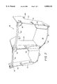
- FIG. 3 is a diagrammatic perspective view of a front panel incorporating a labeling area shown attached to the display rack.
- FIG. 4 is a diagrammatic front view of a removable labeling member for a front panel.
- FIG. 5 is a diagrammatic perspective view of the labeling member of FIG. 4 shown attached to the front panel of FIG. 2.
- Front panel assembly 10 for a display rack, such as a display rack for a commercial refrigerator of the variety used in supermarkets and convenience stores for beverage service for example.
- Front panel assembly 10 is preferably a unitary structure constructed of plastic using an injection molding process, but may be constructed of other materials.
- the front panel assembly 10 has a base 12 with a plurality of legs 14 for supporting front panel 10.
- the front edge of base 12 is preferably curved or contoured to fit the contour of a beverage container.
- Front panel assembly 10 is illustrated as having first, second and third upstanding sidewalls 16, 18, 20 with adjacent sidewalls forming partitions to hold a row of beverage containers therebetween.
- each sidewall has a top end portion, a bottom end portion, and a front edge that extends between the top and bottom end portions of the sidewall.
- each sidewall has a hook 32 formed on a rear portion thereof for connecting the sidewall to the main body of the display rack, and each sidewall defines one or more openings 34 to facilitate connecting the face panel assembly to the display rack.
- the first sidewall 16 is connected along its bottom end portion to base 12 and preferably extends a distance below base 12 equal to the height of the legs 14 so that sidewall 16 supports the right edge of base 12.
- Second sidewall 18 is laterally spaced from first sidewall 16 and is connected along its bottom end portion to base 12. Sidewall 18 also extends below base 12 a distance equal to the height of legs 14 and supports the left side of base 12.
- the lateral spacing between the first and second sidewalls 16, 18 is slightly greater than the width of the beverage container to be displayed between the sidewalls to allow easy movement of the beverage container while preventing it from tilting askew.
- the third sidewall 20 is connected to base 12 in similar fashion to sidewalls 16 and 18, and the second sidewall 18 is intermediate the first and third sidewalls 16, 20. As illustrated, the front panel assembly accommodates two rows of beverage containers with containers in each row aligned one behind the other.
- a first face member 22 has a top end portion and a bottom end portion and is connected to the front edge of the first sidewall 16. Face member 22 extends laterally a preselected distance from first sidewall 16 toward second sidewall 18. When a beverage container is present it rests against face member 22 which prevents the container from falling out of the refrigerator when the door is opened. Face member 22 extends a distance sufficient to interfere with a beverage container to thereby restrain the container from moving forward in the rack. Face member 22 preferably has a curved, undulating, serpentine or sculptured profile for aesthetic appeal and for adding interest to the beverage container.
- a second face member 24 has a top end portion and a bottom end portion and is connected the front edge of second sidewall 18. Second face member 24 extends a preselected distance from second sidewall 18 toward first sidewall 16, and also extends a preselected distance from second sidewall 18 towards third sidewall 20. Both edges of face member 24 have sculptured profiles similar to face member 22 with face member 24 resembling two face members 22 abutting one another back to back.
- Third face member 26 also has a top end portion and a bottom end portion and is connected to the front edge of third sidewall 20. Third face member 26 extends a preselected distance from third sidewall 20 toward second sidewall 18, and also has a sculptured profile.
- the first, second and third face members 22, 24, 26 are preferably connected to base 12 but have sufficient structural integrity when connected only to the sidewalls 16, 18, 20, respectively.
- a first elongated connecting member 28 has a first end connected to the top end portion of first face member 22 and has a second end portion connected to the top end portion of second face member 24.
- First elongated connecting member 28 curves outward away from face members 22 and 24, and is shaped to fit the contour of a beverage container in the rack. It extends outward over the curved portion of base 12.
- Connecting member 28, face members 22 and 24, and base 12 form a first viewing window through which the label of a beverage container can be viewed prior to selection of a beverage from the rack. The window is slightly narrower than the beverage container to help restrain the container.
- the sculptured profiles of the face members increase aesthetic appeal and add interest to labels of beverage containers.
- a second elongated connecting member 30 has a first end connected to the top end portion of second face member 22 and has a second end portion connected to the top end portion of third face member 26.
- First elongated connecting member 30 curves outward away from face members 24 and 26, and is shaped to fit the contour of a beverage container in the rack. It extends outward over the curved portion of base 12.
- Connecting member 30, face members 24 and 26, and base 12 form a second viewing window through which the label of a beverage container can be viewed prior to selection of a beverage from the rack.
- a front panel assembly 36 for a display rack has a base 38 with a plurality of legs 40 for supporting front panel 36.
- the front edge of base 38 is contoured to fit the contour of a beverage container.
- Front panel assembly 36 is shown having first, second and third upstanding sidewalls 42, 44 46 with adjacent sidewalls forming partitions to contain a row beverage containers therebetween.
- Front panel assembly 36 can be formed with only two sidewalls to accommodate a single row of beverage containers or with many sidewalls to accommodate multiple rows.
- Each sidewall has a hook 48 formed on a rear portion thereof for connecting the sidewall to the main body of the display rack, and each sidewall defines one or more openings 50 to facilitate connecting the face panel assembly to the display rack.
- a first face member has a top end portion 52 and a bottom end portion 54 and is connected to the front edge of the first sidewall.
- the first face member extends laterally a preselected distance from first sidewall 42 toward second sidewall 44. When a beverage container is present it rests against the first face member.
- the top end portion 52 of the first face member is planar having a quarter round configuration with a square corner abutting the sidewall and a rounded portion extending toward the second sidewall 44.
- the bottom end portion 54 of the face member is planar having a curved profile with a square corner abutting the sidewall and a curved portion extending toward the second sidewall 44.
- a second face member has a top end portion 56 and a bottom end portion 58 and is connected the front edge of second sidewall.
- the second face member extends laterally a preselected distance from second sidewall 44 toward first sidewall 42, and also extends laterally a preselected distance from second sidewall 44 towards third sidewall 46.
- the top end portion 56 of the second face member is planar having a semicircular configuration with the curved portion extending downward toward the base.
- the bottom end portion 58 of the second face member is planar having a curved profile with the curve pointing upward and a straight portion lying along the base.
- a third face member has a top end portion 60 and a bottom end portion 62 and is connected to the front edge of third sidewall 46.
- the third face member extends laterally a preselected distance from third sidewall 46 toward second sidewall 44.
- the top end portion 60 of the third face member is planar having a quarter round configuration with a square corner abutting the sidewall and a rounded portion extending toward the second sidewall 44.
- the bottom end portion 62 of the face member is planar having a curved profile with a square corner abutting the sidewall and a curved portion extending toward the second sidewall 44.
- a first elongated connecting member 64 has a first end connected to the top end portion 52 of the first face member and has a second end portion connected to the top end portion 56 of the second face member.
- First elongated connecting member 64 curves outward away from top face members 52 and 56, and is shaped to fit the contour of a beverage container in the rack. It extends outward over the curved portion of base 38.
- Connecting member 64, face members 52 and 56, and base 38 form a first viewing window through which the label of a beverage container can be viewed prior to selection of a beverage from the rack.
- the curved profiles of the face members increase aesthetic appeal and add interest to labels of beverage containers.
- a second elongated connecting member 66 has a first end connected to the top end portion 56 of the second face member and has a second end portion connected to the top end portion 60 of the third face member. Second elongated connecting member 66 curves outward away from top face members 56 and 60, and is shaped to fit the contour of a beverage container in the rack. It extends outward over the curved portion of base 38. Connecting member 66, top face members 56 and 60, and base 38 form a second viewing window.
- FIG. 3 wherein another embodiment of the invention is illustrated attached to the main body 68 of a display rack with a beverage container 70 inserted.
- FIG. 3 is similar to FIG. 2 but the connecting member 72 has a larger surface area facing outward toward a consumer, and extends closer toward the base 74 than does the connecting member of FIG. 2.
- Connecting member 72 is preferably attached directly to the front edge face of the sidewall 76 but may be attached to a top end portion of a face member that is attached to the sidewall, such as face member 22 illustrated in FIG. 2.
- Direct attachment of connecting member 72 to sidewall 76 is preferred in this embodiment for two reasons. First, because of its large size and the fact that it extends from the top of the sidewall 76 towards the base 74 and bottom end portions 78-, it is very strong. Second, it is simple to manufacture by injection molding when directly connected.
- Connecting member 72 provides a large surface area that may be transparent so that the label on beverage container 70 is visible through the surface area. Also, the surface area is large enough to have a label or decal affixed to it so that the orientation of a beverage container does not matter when a consumer is making a selection because the decal on connecting member 72 is always facing forward toward the consumer. If a specific container is to be accommodated, then the height of connecting member 72 can be adjusted to coincide with the container label. On some containers, bottles especially, the identifying portion of the label is spaced a certain distance from the bottom of the bottle so that connecting member 72 need not reach all the way to base member 74 or all the way to bottom end portions 78.
- connecting member 72 can be sized and positioned to generally coincide with the upper half of the bottle or with the lower half of the bottle. It is also curved as is connecting member 64 of FIG. 2 to accommodate the curvature of the beverage container.
- FIG. 3 illustrates two front end panels with connecting members side by side but any number could be used to match the number of rows of beverage containers to be accommodated.
- a clip-on panel 80 is an alternative to the connecting member 72 of FIG. 3 with its decal area.
- Panel 80 has a decal area 82 for attaching a product label or decal.
- Decal area 82 is supported on a pair of long legs 84 extending downward from decal area 82 to a connecting base 86 which is curved to fit the contour of a bottle 92 or other container.
- Connecting base 86 is preferably supported on a pair of short legs 88 which separate connecting base 86 from the base 42' of the front panel and provides a channel or area between the two bases to allow any condensation to drain rather than collect and for air to circulate to help prevent condensation. Bacterial and other microbial growth is discouraged by the air circulation and moisture removal.
- Each of the long legs 84 has a series of laterally outward extending protrusions 90a, 90b, 90c that are vertically positioned one above the other.
- Protrusions 90a and 90c are offset to one side of a vertical line while protrusion 90b is offset to the other side of the vertical line forming a slot to receive one of the bottom end portions 54'.
- Each protrusion preferably curves slightly at its distal end to make for easier engagement with bottom end portions 54'.
- Clip-on panel 80 fits inside connecting member 64' and abuts top end portion 52'.
- the display portion has the same curvature as connecting member 64'. As illustrated, the decal area 82 extends above connecting member 64' thereby not obscuring the window area of the front panel.
- a decal or label is attached on the decal area to identify the product in a particular row. Because the decal always faces forward, a high skill worker is not needed to maintain the display rack because container orientation in the rack is no longer required. Decal changes can be made by removing the existing decal and applying a new decal, by applying a new decal over an existing decal, or by replacing the entire clip-on holder. Grasping the holder connecting member and pulling straight upwards causes the protrusions on the long legs to slide up disengaging the face members regardless of whether face members are continuous or separate top and bottom face members. The process is reversed to install a new holder.
- a front panel for a display rack has a base with first and second upstanding sidewalls attached to the base.
- the first sidewall has a top end portion, a bottom end portion and a front edge with the first sidewall connected along its bottom end portion to the base.
- the second sidewall has a top end portion, a bottom end portion and a front edge and is laterally spaced from the first sidewall and connected along its bottom end portion to the base.
- a first face member has a top end portion and a bottom end portion and is connected to the front edge of the first sidewall with the first face member extending laterally a preselected distance from the first sidewall toward the second sidewall.
- a second face member has a top end portion and a bottom end portion and is connected to the front edge of the second sidewall with the second face member extending laterally a preselected distance from the second sidewall toward the first sidewall.
- An elongate connecting member has its first end connected to the top end portion of the first face member and has its second end portion connected to the top end portion of the second face member.
- the front cover is attached to the body of the rack using hooks and openings formed on the front panel that engage members of the rack. It virtually snaps into position on the rack.
- the front cover holds a beverage container in position, first for viewing, and then for selection and removal from the rack by a consumer.
- the container is held upright and forward in the rack so that a container is always ready for removal from the rack.
- the contour of the front panel allows the beverage container to fit all the way forward in the rack, yet be easily lifted out of the rack.
- the members forming the top cross members of the viewing windows are attached to the front face panels instead of the sidewalls allowing a more conforming fit to the container without compromising structural integrity.
- the face members are contoured for visual appeal, but provide maximum strength with minimal dimensions which maximizes the viewing window to take full advantage of manufacturer's labeling.
- the front panel can be enhanced by enlarging the connecting member to include an area large enough to accommodate a label, decal or promotional information.
- the decal area can be made to coincide with a specific area of a beverage container. It can be made to coincide with the label area of a container thereby effectively replacing the container label and allowing random orientation in the display rack.
- the front panel can also be enhanced by adding a clip-on decal holder.
- the clip-on holder has a connecting base supported on a short pair of legs resting on the base of the front panel. The short legs create an air space between the two bases to promote air circulation and prevent condensation.
- Condensation prevention is desirable to retard growth of micro-organisms and to help prevent a beverage container from slipping out of the hand of a consumer as the container is removed from the display rack.
- a pair of long legs rising from the connecting base support a decal holding member which extends upward from the connecting member.
- the long legs have protrusions forming clips to engage the face members of the display rack to hold the clip-on holder in position.
Abstract
Description
Claims (19)
Priority Applications (1)
| Application Number | Priority Date | Filing Date | Title |
|---|---|---|---|
| US09/321,037 US6068142A (en) | 1999-05-27 | 1999-05-27 | Front panel for a display rack |
Applications Claiming Priority (1)
| Application Number | Priority Date | Filing Date | Title |
|---|---|---|---|
| US09/321,037 US6068142A (en) | 1999-05-27 | 1999-05-27 | Front panel for a display rack |
Publications (1)
| Publication Number | Publication Date |
|---|---|
| US6068142A true US6068142A (en) | 2000-05-30 |
Family
ID=23248912
Family Applications (1)
| Application Number | Title | Priority Date | Filing Date |
|---|---|---|---|
| US09/321,037 Expired - Lifetime US6068142A (en) | 1999-05-27 | 1999-05-27 | Front panel for a display rack |
Country Status (1)
| Country | Link |
|---|---|
| US (1) | US6068142A (en) |
Cited By (57)
| Publication number | Priority date | Publication date | Assignee | Title |
|---|---|---|---|---|
| US6325221B2 (en) * | 1997-11-08 | 2001-12-04 | Display Industries, Llc | Merchandising display track device of multiple-piece construction |
| US6513677B1 (en) * | 1997-10-14 | 2003-02-04 | Gross-Given Manufacturing Company | Apparatus and method for vending products |
| US6679389B1 (en) * | 2002-07-29 | 2004-01-20 | Display Industries, Llc | Front piece for a merchandising display track device |
| US20040020877A1 (en) * | 2002-08-01 | 2004-02-05 | Paul Flum Ideas, Inc. | Product merchandising display unit with pull through front wall members |
| US6702127B2 (en) | 2002-03-11 | 2004-03-09 | Display Industries, Llc. | Display track device with anti-torsion front cylinder |
| US20040056042A1 (en) * | 2002-07-05 | 2004-03-25 | Skavnak James E. | Apparatus and method for vending products having various dimensions |
| US6722509B1 (en) | 2002-10-31 | 2004-04-20 | Display Industries, Llc. | Display track device with front panels and top stop members |
| US20040084391A1 (en) * | 2002-10-31 | 2004-05-06 | Bernard Primiano | Display track device with anti-torsion bar |
| US20040183417A1 (en) * | 2003-03-19 | 2004-09-23 | Ahmed Rania Mohanna | Refrigerator door beverage storage module |
| US20050067362A1 (en) * | 2001-06-08 | 2005-03-31 | Martin Arthur R. | Display system |
| US20050189370A1 (en) * | 2004-02-27 | 2005-09-01 | The Vendo Company | Vending machine and component parts |
| US20060138065A1 (en) * | 1999-12-08 | 2006-06-29 | Squitieri Anthony C | Glide |
| US20060237384A1 (en) * | 2005-04-20 | 2006-10-26 | Eric Neumann | Track unit with removable partitions |
| US20070080166A1 (en) * | 2005-10-12 | 2007-04-12 | Rtc Industries, Inc. | Cylindrical container dispenser |
| US20070193318A1 (en) * | 2006-01-27 | 2007-08-23 | Alex Churchill | Consumer product dispensing system |
| US20070251996A1 (en) * | 2006-04-26 | 2007-11-01 | Dimitri Kanevsky | Verification of a biometric identification |
| US20070256992A1 (en) * | 2006-05-04 | 2007-11-08 | Carl Olson | Shelf divider system |
| US20080061076A1 (en) * | 2004-02-27 | 2008-03-13 | Sandenvendo America, Inc. | Retrieval systems for vending machines |
| US20080129161A1 (en) * | 2006-10-23 | 2008-06-05 | Rtc Industries, Inc. | Merchandising System with Flippable Column and/or Item Stop |
| US20080135574A1 (en) * | 2004-02-27 | 2008-06-12 | Sanden Vendo America, Inc. | Product acquisition devices and methods for vending machines |
| US20080223804A1 (en) * | 2007-03-14 | 2008-09-18 | Riley Daniel C | Display rack with ventilation window in the vertical walls |
| US7823734B2 (en) | 2005-09-12 | 2010-11-02 | Rtc Industries, Inc. | Product management display system with trackless pusher mechanism |
| US20110094980A1 (en) * | 2009-10-23 | 2011-04-28 | Cousin Serge L | Display channel apparatus |
| US8312999B2 (en) | 2005-09-12 | 2012-11-20 | Rtc Industries, Inc. | Product management display system with trackless pusher mechanism |
| US20130031815A1 (en) * | 2005-09-12 | 2013-02-07 | Rtc Industries Inc. | Product Management Display System with Trackless Pusher Mechanism |
| US8453850B2 (en) | 2005-09-12 | 2013-06-04 | Rtc Industries, Inc. | Product management display system with trackless pusher mechanism |
| US8739984B2 (en) | 2005-09-12 | 2014-06-03 | Rtc Industries, Inc. | Product management display system with trackless pusher mechanism |
| US20140175032A1 (en) * | 2012-12-20 | 2014-06-26 | Hon Hai Precision Industry Co., Ltd. | Mounting apparatus for goods channel |
| US8967394B2 (en) | 2005-09-12 | 2015-03-03 | Rtc Industries, Inc. | Product management display system with trackless pusher mechanism |
| US8978904B2 (en) | 2005-09-12 | 2015-03-17 | Rtc Industries, Inc. | Product management display system with trackless pusher mechanism |
| US9060624B2 (en) | 2005-09-12 | 2015-06-23 | Rtc Industries, Inc. | Product management display system with rail mounting clip |
| US20150208830A1 (en) * | 2014-01-24 | 2015-07-30 | Rtc Industries, Inc. | Product management display system |
| US9138075B2 (en) | 2005-09-12 | 2015-09-22 | Rtc Industries, Inc. | Product management display system |
| US9144326B2 (en) | 2002-08-20 | 2015-09-29 | Gamon Plus, Inc. | Multi-chute gravity feed dispenser display |
| US9173504B2 (en) | 2005-09-12 | 2015-11-03 | Rtc Industries, Inc. | Product management display system |
| US9232864B2 (en) | 2005-09-12 | 2016-01-12 | RTC Industries, Incorporated | Product management display system with trackless pusher mechanism |
| US9259102B2 (en) | 2005-09-12 | 2016-02-16 | RTC Industries, Incorporated | Product management display system with trackless pusher mechanism |
| US9265358B2 (en) | 2005-09-12 | 2016-02-23 | RTC Industries, Incorporated | Product management display system |
| US9265362B2 (en) | 2005-09-12 | 2016-02-23 | RTC Industries, Incorporated | Product management display system |
| US20160088955A1 (en) * | 2014-09-26 | 2016-03-31 | Eva Lilja | Channel glide assemblies |
| US9486088B2 (en) | 2005-09-12 | 2016-11-08 | Rtc Industries, Inc. | Product management display system |
| US9750354B2 (en) | 2005-09-12 | 2017-09-05 | Rtc Industries, Inc. | Product management display system |
| USD801734S1 (en) | 2014-12-01 | 2017-11-07 | Retail Space Solutions Llc | Shelf management parts |
| US9955802B2 (en) | 2015-04-08 | 2018-05-01 | Fasteners For Retail, Inc. | Divider with selectively securable track assembly |
| US10154739B2 (en) | 2013-12-02 | 2018-12-18 | Retail Space Solutions Llc | Universal merchandiser and methods relating to same |
| US10178909B2 (en) | 2016-01-13 | 2019-01-15 | Rtc Industries, Inc. | Anti-splay device for merchandise display system |
| US10285510B2 (en) | 2005-09-12 | 2019-05-14 | Rtc Industries, Inc. | Product management display system |
| US10448756B2 (en) | 2017-06-16 | 2019-10-22 | Rtc Industries, Inc. | Product management display system with trackless pusher mechanism |
| US10905256B2 (en) | 2002-08-20 | 2021-02-02 | Gamon Plus, Inc. | Multi-chute gravity feed dispenser display |
| US10952546B2 (en) | 2005-09-12 | 2021-03-23 | Rtc Industries, Inc. | Product management display system with trackless pusher mechanism |
| US10959540B2 (en) | 2016-12-05 | 2021-03-30 | Retail Space Solutions Llc | Shelf management system, components thereof, and related methods |
| US11045017B2 (en) | 2017-04-27 | 2021-06-29 | Retail Space Solutions Llc | Shelf-mounted tray and methods relating to same |
| US11259652B2 (en) | 2005-09-12 | 2022-03-01 | Rtc Industries, Inc. | Product management display system |
| USD952380S1 (en) * | 2019-08-26 | 2022-05-24 | Marmon Foodservice Technologies, Inc. | Product display lens |
| USD952381S1 (en) * | 2019-11-08 | 2022-05-24 | Marmon Foodservice Technologies, Inc. | Product display unit |
| US11344138B2 (en) | 2005-09-12 | 2022-05-31 | Rtc Industries, Inc. | Product management display system |
| US11583109B2 (en) | 2005-09-12 | 2023-02-21 | Rtc Industries, Inc. | Product management display system with trackless pusher mechanism |
Citations (8)
| Publication number | Priority date | Publication date | Assignee | Title |
|---|---|---|---|---|
| US4205763A (en) * | 1978-12-26 | 1980-06-03 | Marlboro Marketing, Inc. | Container dispensing device |
| US5240126A (en) * | 1992-05-29 | 1993-08-31 | The Gillette Company | Dispensing rack apparatus |
| US5624042A (en) * | 1994-06-15 | 1997-04-29 | Paul Flum Ideas, Inc. | Variable width product merchandising display unit having detachable/reattachable side track portions |
| US5645176A (en) * | 1996-08-08 | 1997-07-08 | Display Technologies, Inc. | Display rack with channel front member |
| US5695074A (en) * | 1995-10-10 | 1997-12-09 | Henschel-Steinau, Inc. | Gravity feed bottle display and dispensing rack |
| US5865324A (en) * | 1997-09-25 | 1999-02-02 | Display Technologies, Inc. | Roto-track display device |
| US5904256A (en) * | 1998-02-13 | 1999-05-18 | Display Technologies, Inc. | Offset locking device for display channels |
| US5971204A (en) * | 1997-10-17 | 1999-10-26 | Rehrig Pacific Company | Bottle dispenser |
-
1999
- 1999-05-27 US US09/321,037 patent/US6068142A/en not_active Expired - Lifetime
Patent Citations (8)
| Publication number | Priority date | Publication date | Assignee | Title |
|---|---|---|---|---|
| US4205763A (en) * | 1978-12-26 | 1980-06-03 | Marlboro Marketing, Inc. | Container dispensing device |
| US5240126A (en) * | 1992-05-29 | 1993-08-31 | The Gillette Company | Dispensing rack apparatus |
| US5624042A (en) * | 1994-06-15 | 1997-04-29 | Paul Flum Ideas, Inc. | Variable width product merchandising display unit having detachable/reattachable side track portions |
| US5695074A (en) * | 1995-10-10 | 1997-12-09 | Henschel-Steinau, Inc. | Gravity feed bottle display and dispensing rack |
| US5645176A (en) * | 1996-08-08 | 1997-07-08 | Display Technologies, Inc. | Display rack with channel front member |
| US5865324A (en) * | 1997-09-25 | 1999-02-02 | Display Technologies, Inc. | Roto-track display device |
| US5971204A (en) * | 1997-10-17 | 1999-10-26 | Rehrig Pacific Company | Bottle dispenser |
| US5904256A (en) * | 1998-02-13 | 1999-05-18 | Display Technologies, Inc. | Offset locking device for display channels |
Cited By (140)
| Publication number | Priority date | Publication date | Assignee | Title |
|---|---|---|---|---|
| US6513677B1 (en) * | 1997-10-14 | 2003-02-04 | Gross-Given Manufacturing Company | Apparatus and method for vending products |
| US6325221B2 (en) * | 1997-11-08 | 2001-12-04 | Display Industries, Llc | Merchandising display track device of multiple-piece construction |
| US20060138065A1 (en) * | 1999-12-08 | 2006-06-29 | Squitieri Anthony C | Glide |
| US7182209B2 (en) | 1999-12-08 | 2007-02-27 | Display Technologies, Llc | Glide |
| US7083054B2 (en) * | 2000-12-08 | 2006-08-01 | Display Technologies, Inc. | Retail display unit |
| US20050067362A1 (en) * | 2001-06-08 | 2005-03-31 | Martin Arthur R. | Display system |
| US7311212B2 (en) | 2001-06-08 | 2007-12-25 | Mechtronics Corporation | Display system |
| US6702127B2 (en) | 2002-03-11 | 2004-03-09 | Display Industries, Llc. | Display track device with anti-torsion front cylinder |
| US6966455B2 (en) | 2002-07-05 | 2005-11-22 | Gross-Given Manufacturing Company | Apparatus and method for vending products having various dimensions |
| US20070210100A1 (en) * | 2002-07-05 | 2007-09-13 | Skavnak James E | Apparatus and method for vending products having various dimensions |
| US20040056042A1 (en) * | 2002-07-05 | 2004-03-25 | Skavnak James E. | Apparatus and method for vending products having various dimensions |
| US20050284879A1 (en) * | 2002-07-05 | 2005-12-29 | Gross-Given Manufacturing Company | Apparatus and method for vending products having various dimensions |
| US7128239B2 (en) | 2002-07-05 | 2006-10-31 | Automatic Products International, Ltd. | Apparatus and method for vending products having various dimensions |
| US6679389B1 (en) * | 2002-07-29 | 2004-01-20 | Display Industries, Llc | Front piece for a merchandising display track device |
| US6715621B2 (en) * | 2002-08-01 | 2004-04-06 | Paul Flum Ideas, Inc. | Product merchandising display unit with pull through front wall members |
| US20040020877A1 (en) * | 2002-08-01 | 2004-02-05 | Paul Flum Ideas, Inc. | Product merchandising display unit with pull through front wall members |
| US9144326B2 (en) | 2002-08-20 | 2015-09-29 | Gamon Plus, Inc. | Multi-chute gravity feed dispenser display |
| US10149554B2 (en) | 2002-08-20 | 2018-12-11 | Gamon Plus, Inc. | Multi-chute gravity feed dispenser display and method |
| US10905256B2 (en) | 2002-08-20 | 2021-02-02 | Gamon Plus, Inc. | Multi-chute gravity feed dispenser display |
| US20040084391A1 (en) * | 2002-10-31 | 2004-05-06 | Bernard Primiano | Display track device with anti-torsion bar |
| US6722509B1 (en) | 2002-10-31 | 2004-04-20 | Display Industries, Llc. | Display track device with front panels and top stop members |
| US7104410B2 (en) * | 2002-10-31 | 2006-09-12 | Display Industries, Llc. | Display track device with anti-torsion bar |
| US7334853B2 (en) | 2003-03-19 | 2008-02-26 | General Electric Company | Refrigerator door beverage storage module |
| US20040183417A1 (en) * | 2003-03-19 | 2004-09-23 | Ahmed Rania Mohanna | Refrigerator door beverage storage module |
| US7823750B2 (en) | 2004-02-27 | 2010-11-02 | Sanden Vendo America, Inc. | Product delivery systems for vending machines |
| US20050189370A1 (en) * | 2004-02-27 | 2005-09-01 | The Vendo Company | Vending machine and component parts |
| US20080061076A1 (en) * | 2004-02-27 | 2008-03-13 | Sandenvendo America, Inc. | Retrieval systems for vending machines |
| US20080067189A1 (en) * | 2004-02-27 | 2008-03-20 | Sandenvendo America, Inc. | Retrieval systems for vending machines |
| US20080067183A1 (en) * | 2004-02-27 | 2008-03-20 | Sandenvendo America, Inc. | Modular cabinet for vending machines |
| US8162174B2 (en) | 2004-02-27 | 2012-04-24 | Sandenvendo America, Inc. | Retrieval systems for vending machines |
| US20080135574A1 (en) * | 2004-02-27 | 2008-06-12 | Sanden Vendo America, Inc. | Product acquisition devices and methods for vending machines |
| US7904199B2 (en) | 2004-02-27 | 2011-03-08 | Sanden Vendo America, Inc. | Calibration systems for machines |
| US7886930B2 (en) | 2004-02-27 | 2011-02-15 | Sandenvendo America, Inc. | Modular cabinet for vending machines |
| US7837059B2 (en) | 2004-02-27 | 2010-11-23 | Sanden Vendo America, Inc. | Product acquisition devices and methods for vending machines |
| US20060237384A1 (en) * | 2005-04-20 | 2006-10-26 | Eric Neumann | Track unit with removable partitions |
| US9237816B2 (en) | 2005-09-12 | 2016-01-19 | RTC Industries, Incorporated | Product management display system with trackless pusher mechanism |
| US10959542B2 (en) | 2005-09-12 | 2021-03-30 | Rtc Industries, Inc. | Product management display system with trackless pusher mechanism |
| US11583109B2 (en) | 2005-09-12 | 2023-02-21 | Rtc Industries, Inc. | Product management display system with trackless pusher mechanism |
| US11517126B2 (en) * | 2005-09-12 | 2022-12-06 | Rtc Industries, Inc. | Product management display system |
| US11490743B2 (en) | 2005-09-12 | 2022-11-08 | Rtc Industries, Inc. | Product management display system |
| US11484131B2 (en) | 2005-09-12 | 2022-11-01 | Rtc Industries, Inc. | Product management display system with trackless pusher mechanism |
| US8127944B2 (en) | 2005-09-12 | 2012-03-06 | Rtc Industries, Inc. | Product management display system with trackless pusher mechanism |
| US11464346B2 (en) * | 2005-09-12 | 2022-10-11 | Rtc Industries, Inc. | Product management display system |
| US8312999B2 (en) | 2005-09-12 | 2012-11-20 | Rtc Industries, Inc. | Product management display system with trackless pusher mechanism |
| US8360253B2 (en) | 2005-09-12 | 2013-01-29 | Rtc Industries, Inc. | Product management display system with trackless pusher mechanism |
| US20130031815A1 (en) * | 2005-09-12 | 2013-02-07 | Rtc Industries Inc. | Product Management Display System with Trackless Pusher Mechanism |
| US8453850B2 (en) | 2005-09-12 | 2013-06-04 | Rtc Industries, Inc. | Product management display system with trackless pusher mechanism |
| US8469205B1 (en) | 2005-09-12 | 2013-06-25 | Rtc Industries, Inc. | Product management display system with trackless pusher mechanism |
| US8550262B2 (en) | 2005-09-12 | 2013-10-08 | Rtc Industries, Inc. | Product management display system with trackless pusher mechanism |
| US8739984B2 (en) | 2005-09-12 | 2014-06-03 | Rtc Industries, Inc. | Product management display system with trackless pusher mechanism |
| US11452386B2 (en) * | 2005-09-12 | 2022-09-27 | Rtc Industries, Inc. | Product management display system with trackless pusher mechanism |
| US8863963B2 (en) * | 2005-09-12 | 2014-10-21 | Rtc Industries, Inc. | Product management display system with trackless pusher mechanism |
| US8967394B2 (en) | 2005-09-12 | 2015-03-03 | Rtc Industries, Inc. | Product management display system with trackless pusher mechanism |
| US8978904B2 (en) | 2005-09-12 | 2015-03-17 | Rtc Industries, Inc. | Product management display system with trackless pusher mechanism |
| US8978903B2 (en) | 2005-09-12 | 2015-03-17 | Rtc Industries, Inc. | Product management display system with trackless pusher mechanism |
| US8998005B2 (en) | 2005-09-12 | 2015-04-07 | Rtc Industries, Inc. | Product management display system with trackless pusher mechanism |
| US9060624B2 (en) | 2005-09-12 | 2015-06-23 | Rtc Industries, Inc. | Product management display system with rail mounting clip |
| US9072394B2 (en) | 2005-09-12 | 2015-07-07 | Rtc Industries, Inc. | Product management display system with trackless pusher mechanism |
| US11344138B2 (en) | 2005-09-12 | 2022-05-31 | Rtc Industries, Inc. | Product management display system |
| US11259652B2 (en) | 2005-09-12 | 2022-03-01 | Rtc Industries, Inc. | Product management display system |
| US9107515B2 (en) | 2005-09-12 | 2015-08-18 | Rtc Industries, Inc. | Product management display system with trackless pusher mechanism |
| US11076707B2 (en) | 2005-09-12 | 2021-08-03 | Rtc Industries, Inc. | Product management display system with trackless pusher mechanism |
| US9138075B2 (en) | 2005-09-12 | 2015-09-22 | Rtc Industries, Inc. | Product management display system |
| US11058232B2 (en) * | 2005-09-12 | 2021-07-13 | Rtc Industries, Inc. | Product management display system |
| US9149132B2 (en) | 2005-09-12 | 2015-10-06 | Rtc Industries, Inc. | Product management display system with trackless pusher mechanism |
| US9173505B2 (en) | 2005-09-12 | 2015-11-03 | Rtc Industries, Inc. | Product management display system with trackless pusher mechanism |
| US9173504B2 (en) | 2005-09-12 | 2015-11-03 | Rtc Industries, Inc. | Product management display system |
| US10966546B2 (en) * | 2005-09-12 | 2021-04-06 | Rtc Industries, Inc. | Product management display system |
| US9185999B2 (en) | 2005-09-12 | 2015-11-17 | Rtc Industries, Inc. | Product management display system with trackless pusher mechanism |
| US9232864B2 (en) | 2005-09-12 | 2016-01-12 | RTC Industries, Incorporated | Product management display system with trackless pusher mechanism |
| US20200000245A1 (en) * | 2005-09-12 | 2020-01-02 | Rtc Industries, Inc. | Product management display system |
| US9259102B2 (en) | 2005-09-12 | 2016-02-16 | RTC Industries, Incorporated | Product management display system with trackless pusher mechanism |
| US9265358B2 (en) | 2005-09-12 | 2016-02-23 | RTC Industries, Incorporated | Product management display system |
| US9265362B2 (en) | 2005-09-12 | 2016-02-23 | RTC Industries, Incorporated | Product management display system |
| US10952546B2 (en) | 2005-09-12 | 2021-03-23 | Rtc Industries, Inc. | Product management display system with trackless pusher mechanism |
| US9402485B2 (en) | 2005-09-12 | 2016-08-02 | Rtc Industries, Inc. | Product management display system with trackless pusher mechanism |
| US9486088B2 (en) | 2005-09-12 | 2016-11-08 | Rtc Industries, Inc. | Product management display system |
| US9498057B2 (en) | 2005-09-12 | 2016-11-22 | Rtc Industries, Inc. | Product management display system with trackless pusher mechanism |
| US9504321B2 (en) | 2005-09-12 | 2016-11-29 | Rtc Industries, Inc. | Product management display system with trackless pusher mechanism |
| US9510677B2 (en) | 2005-09-12 | 2016-12-06 | Rtc Industries, Inc. | Product management display system with rail mounting clip |
| US9532658B2 (en) | 2005-09-12 | 2017-01-03 | Rtc Industries, Inc. | Product management display system |
| US9635957B2 (en) | 2005-09-12 | 2017-05-02 | Rtc Industries, Inc. | Product management display system |
| US9713393B2 (en) | 2005-09-12 | 2017-07-25 | Rtc Industries, Inc. | Product management display system |
| US9730531B2 (en) | 2005-09-12 | 2017-08-15 | Rtc Industries, Inc. | Product management display system with trackless pusher mechanism |
| US9750354B2 (en) | 2005-09-12 | 2017-09-05 | Rtc Industries, Inc. | Product management display system |
| US10905258B2 (en) | 2005-09-12 | 2021-02-02 | Rtc Industries, Inc. | Product management display system |
| US7823734B2 (en) | 2005-09-12 | 2010-11-02 | Rtc Industries, Inc. | Product management display system with trackless pusher mechanism |
| US9820584B2 (en) | 2005-09-12 | 2017-11-21 | Rtc Industries, Inc. | Product management display system |
| US9820585B2 (en) | 2005-09-12 | 2017-11-21 | Rtc Industries, Inc. | Product management display system with trackless pusher mechanism |
| US9895007B2 (en) | 2005-09-12 | 2018-02-20 | Rtc Industries, Inc. | Product management display system with trackless pusher mechanism |
| US9918565B2 (en) | 2005-09-12 | 2018-03-20 | Rtc Industries, Inc. | Product management display system |
| US9930973B2 (en) | 2005-09-12 | 2018-04-03 | Rtc Industries, Inc. | Product management display system with trackless pusher mechanism |
| US10702079B2 (en) | 2005-09-12 | 2020-07-07 | Rtc Industries, Inc. | Product management display system with trackless pusher mechanism |
| US9968206B2 (en) | 2005-09-12 | 2018-05-15 | Rtc Industries, Inc. | Product management display system |
| US10045640B2 (en) | 2005-09-12 | 2018-08-14 | Rtc Industries, Inc. | Product management display system with trackless pusher mechanism |
| US10702075B2 (en) | 2005-09-12 | 2020-07-07 | Rtc Industries, Inc. | Product management display system |
| US10631666B2 (en) | 2005-09-12 | 2020-04-28 | Rtc Industries, Inc. | Product management display system |
| US10165871B2 (en) | 2005-09-12 | 2019-01-01 | Rtc Industries, Inc. | Product management display system with trackless pusher mechanism |
| US10568438B2 (en) | 2005-09-12 | 2020-02-25 | Rtc Industries, Inc. | Product management display system with trackless pusher mechanism |
| US10206520B2 (en) | 2005-09-12 | 2019-02-19 | Rtc Industries, Inc. | Product management display system |
| US10226137B2 (en) | 2005-09-12 | 2019-03-12 | Rtc Industries, Inc. | Product management display system |
| US10278516B2 (en) | 2005-09-12 | 2019-05-07 | Rtc Industries, Inc. | Product management display system |
| US10285510B2 (en) | 2005-09-12 | 2019-05-14 | Rtc Industries, Inc. | Product management display system |
| US10555624B2 (en) | 2005-09-12 | 2020-02-11 | Rtc Industries, Inc. | Product management display system with trackless pusher mechanism |
| US20070080166A1 (en) * | 2005-10-12 | 2007-04-12 | Rtc Industries, Inc. | Cylindrical container dispenser |
| US7757890B2 (en) | 2005-10-12 | 2010-07-20 | Rtc Industries, Inc. | Cylindrical container dispenser |
| US20070193318A1 (en) * | 2006-01-27 | 2007-08-23 | Alex Churchill | Consumer product dispensing system |
| US20070251996A1 (en) * | 2006-04-26 | 2007-11-01 | Dimitri Kanevsky | Verification of a biometric identification |
| US20070256992A1 (en) * | 2006-05-04 | 2007-11-08 | Carl Olson | Shelf divider system |
| US8056734B2 (en) | 2006-10-23 | 2011-11-15 | Rtc Industries, Inc. | Merchandising system with flippable column and/or item stop |
| US20080129161A1 (en) * | 2006-10-23 | 2008-06-05 | Rtc Industries, Inc. | Merchandising System with Flippable Column and/or Item Stop |
| US20080223804A1 (en) * | 2007-03-14 | 2008-09-18 | Riley Daniel C | Display rack with ventilation window in the vertical walls |
| US20110094980A1 (en) * | 2009-10-23 | 2011-04-28 | Cousin Serge L | Display channel apparatus |
| US20140175032A1 (en) * | 2012-12-20 | 2014-06-26 | Hon Hai Precision Industry Co., Ltd. | Mounting apparatus for goods channel |
| US10154739B2 (en) | 2013-12-02 | 2018-12-18 | Retail Space Solutions Llc | Universal merchandiser and methods relating to same |
| US20150208830A1 (en) * | 2014-01-24 | 2015-07-30 | Rtc Industries, Inc. | Product management display system |
| US9179788B2 (en) * | 2014-01-24 | 2015-11-10 | Rtc Industries, Inc. | Product management display system |
| US20150216324A1 (en) * | 2014-01-24 | 2015-08-06 | Rtc Industries, Inc. | Product Management Display System |
| US9138076B2 (en) * | 2014-01-24 | 2015-09-22 | Rtc Industries, Inc. | Product management display system |
| US9801466B2 (en) * | 2014-01-24 | 2017-10-31 | Rtc Industries, Inc. | Product management display system |
| US10368657B2 (en) * | 2014-09-26 | 2019-08-06 | Eva Lilja | Channel glide assemblies |
| US10806275B2 (en) | 2014-09-26 | 2020-10-20 | Eva Lilja | Channel glide assemblies |
| US20160088955A1 (en) * | 2014-09-26 | 2016-03-31 | Eva Lilja | Channel glide assemblies |
| US10455953B2 (en) | 2014-09-26 | 2019-10-29 | Monster Energy Company | Channel glide assemblies |
| US11439252B2 (en) * | 2014-09-26 | 2022-09-13 | Eva Lilja | Channel glide assemblies |
| USD801734S1 (en) | 2014-12-01 | 2017-11-07 | Retail Space Solutions Llc | Shelf management parts |
| USD874197S1 (en) | 2014-12-01 | 2020-02-04 | Retail Space Solutions Llc | Shelf management dividers |
| US11122915B2 (en) | 2015-04-08 | 2021-09-21 | Fasteners For Retail, Inc. | Divider with selectively securable track assembly |
| US11690463B2 (en) | 2015-04-08 | 2023-07-04 | Fasteners For Retail, Inc. | Divider with selectively securable track assembly |
| US9955802B2 (en) | 2015-04-08 | 2018-05-01 | Fasteners For Retail, Inc. | Divider with selectively securable track assembly |
| US10588426B2 (en) | 2015-04-08 | 2020-03-17 | Fasteners For Retail, Inc. | Divider with selectively securable track assembly |
| US10178909B2 (en) | 2016-01-13 | 2019-01-15 | Rtc Industries, Inc. | Anti-splay device for merchandise display system |
| US10959540B2 (en) | 2016-12-05 | 2021-03-30 | Retail Space Solutions Llc | Shelf management system, components thereof, and related methods |
| US11045017B2 (en) | 2017-04-27 | 2021-06-29 | Retail Space Solutions Llc | Shelf-mounted tray and methods relating to same |
| US10448756B2 (en) | 2017-06-16 | 2019-10-22 | Rtc Industries, Inc. | Product management display system with trackless pusher mechanism |
| US10952549B2 (en) | 2017-06-16 | 2021-03-23 | Rtc Industries, Inc. | Product management display system with trackless pusher mechanism |
| US11730286B2 (en) * | 2017-06-16 | 2023-08-22 | Rtc Industries, Inc. | Product management display system with trackless pusher mechanism |
| USD952380S1 (en) * | 2019-08-26 | 2022-05-24 | Marmon Foodservice Technologies, Inc. | Product display lens |
| USD952381S1 (en) * | 2019-11-08 | 2022-05-24 | Marmon Foodservice Technologies, Inc. | Product display unit |
| USD990204S1 (en) * | 2019-11-08 | 2023-06-27 | Marmon Foodservice Technologies, Inc. | Product display unit |
Similar Documents
| Publication | Publication Date | Title |
|---|---|---|
| US6068142A (en) | Front panel for a display rack | |
| US8333285B2 (en) | Track for a display case | |
| US5201191A (en) | Refrigerated merchandiser | |
| US6688478B2 (en) | Product storage and merchandising unit | |
| US6679389B1 (en) | Front piece for a merchandising display track device | |
| US5450968A (en) | Shelving system with adjustable width merchandise channels | |
| US4478337A (en) | Adjustable shelving unit | |
| US10806275B2 (en) | Channel glide assemblies | |
| US20040004046A1 (en) | Merchandising display track device | |
| US20010020605A1 (en) | Shelf assembly having product holders | |
| US6571967B2 (en) | Display shelf with product anchors | |
| US6588606B2 (en) | Product merchandising assembly | |
| US8671603B2 (en) | Decorative and informative signage | |
| US7306106B2 (en) | Cooler door shelf device with flexible display | |
| US4938368A (en) | Merchandise display and dispenser rack | |
| US7080744B2 (en) | Vented cooler door shelf device | |
| US20030209505A1 (en) | Display shelf for stackable products | |
| US7216445B2 (en) | Method and apparatus for displaying a sign | |
| US20060043036A1 (en) | Cooler door shelf device with removable product panel | |
| US6044983A (en) | Shelf structure | |
| US20030115898A1 (en) | Dual purpose product merchandising unit | |
| US20070045145A1 (en) | Horizontally nestable document holder | |
| CN219813703U (en) | Combined structure of shelf of display cabinet | |
| US20050167376A1 (en) | Merchandise display apparatus | |
| US10772441B1 (en) | Multi-level riser display and storage system |
Legal Events
| Date | Code | Title | Description |
|---|---|---|---|
| AS | Assignment |
Owner name: DISPLAY INDUSTRIES, LLC, GEORGIA Free format text: ASSIGNMENT OF ASSIGNORS INTEREST;ASSIGNOR:PRIMIANO, BERNARD;REEL/FRAME:010210/0508 Effective date: 19990525 |
|
| STCF | Information on status: patent grant |
Free format text: PATENTED CASE |
|
| AS | Assignment |
Owner name: SOUTHTRUST BANK, ALABAMA Free format text: SECURITY AGREEMENT;ASSIGNOR:DISPLAY INDUSTRIES, LLC;REEL/FRAME:013203/0845 Effective date: 20020408 |
|
| FPAY | Fee payment |
Year of fee payment: 4 |
|
| FPAY | Fee payment |
Year of fee payment: 8 |
|
| FPAY | Fee payment |
Year of fee payment: 12 |
|
| AS | Assignment |
Owner name: FCC, LLC D/B/A FIRST CAPITAL, GEORGIA Free format text: SECURITY AGREEMENT;ASSIGNOR:DISPLAY INDUSTRIES, LLC;REEL/FRAME:028467/0968 Effective date: 20120625 |
|
| AS | Assignment |
Owner name: BIG SHOULDERS CAPITAL, LLC, ILLINOIS Free format text: ASSIGNMENT AND ASSUMPTION OF A SECURITY INTEREST;ASSIGNOR:FCC, LLC D/B/A FIRST CAPITAL;REEL/FRAME:036537/0820 Effective date: 20150811 |