US6076025A - Mobile robot steering method and control device - Google Patents
Mobile robot steering method and control device Download PDFInfo
- Publication number
- US6076025A US6076025A US09/015,312 US1531298A US6076025A US 6076025 A US6076025 A US 6076025A US 1531298 A US1531298 A US 1531298A US 6076025 A US6076025 A US 6076025A
- Authority
- US
- United States
- Prior art keywords
- running
- robot
- motion
- mobile robot
- turning
- Prior art date
- Legal status (The legal status is an assumption and is not a legal conclusion. Google has not performed a legal analysis and makes no representation as to the accuracy of the status listed.)
- Expired - Lifetime
Links
- 238000000034 method Methods 0.000 title claims description 57
- 238000007514 turning Methods 0.000 claims abstract description 74
- 238000001514 detection method Methods 0.000 claims abstract description 24
- 238000004088 simulation Methods 0.000 claims abstract description 14
- 230000033001 locomotion Effects 0.000 claims description 128
- 230000004044 response Effects 0.000 claims description 11
- 238000012913 prioritisation Methods 0.000 claims 2
- 230000009471 action Effects 0.000 description 17
- 230000001276 controlling effect Effects 0.000 description 12
- 230000008569 process Effects 0.000 description 11
- 238000010586 diagram Methods 0.000 description 9
- 230000005540 biological transmission Effects 0.000 description 3
- 238000004140 cleaning Methods 0.000 description 3
- 238000010276 construction Methods 0.000 description 3
- 230000002265 prevention Effects 0.000 description 3
- 238000013507 mapping Methods 0.000 description 2
- 238000004364 calculation method Methods 0.000 description 1
- 230000001143 conditioned effect Effects 0.000 description 1
- 230000003247 decreasing effect Effects 0.000 description 1
- 238000002474 experimental method Methods 0.000 description 1
- 230000003287 optical effect Effects 0.000 description 1
- 230000001172 regenerating effect Effects 0.000 description 1
Images

Classifications
-
- G—PHYSICS
- G05—CONTROLLING; REGULATING
- G05D—SYSTEMS FOR CONTROLLING OR REGULATING NON-ELECTRIC VARIABLES
- G05D1/00—Control of position, course or altitude of land, water, air, or space vehicles, e.g. automatic pilot
- G05D1/02—Control of position or course in two dimensions
- G05D1/021—Control of position or course in two dimensions specially adapted to land vehicles
- G05D1/0212—Control of position or course in two dimensions specially adapted to land vehicles with means for defining a desired trajectory
- G05D1/0219—Control of position or course in two dimensions specially adapted to land vehicles with means for defining a desired trajectory ensuring the processing of the whole working surface
-
- G—PHYSICS
- G05—CONTROLLING; REGULATING
- G05D—SYSTEMS FOR CONTROLLING OR REGULATING NON-ELECTRIC VARIABLES
- G05D1/00—Control of position, course or altitude of land, water, air, or space vehicles, e.g. automatic pilot
- G05D1/02—Control of position or course in two dimensions
- G05D1/021—Control of position or course in two dimensions specially adapted to land vehicles
- G05D1/0231—Control of position or course in two dimensions specially adapted to land vehicles using optical position detecting means
- G05D1/0238—Control of position or course in two dimensions specially adapted to land vehicles using optical position detecting means using obstacle or wall sensors
-
- G—PHYSICS
- G05—CONTROLLING; REGULATING
- G05D—SYSTEMS FOR CONTROLLING OR REGULATING NON-ELECTRIC VARIABLES
- G05D1/00—Control of position, course or altitude of land, water, air, or space vehicles, e.g. automatic pilot
- G05D1/02—Control of position or course in two dimensions
- G05D1/021—Control of position or course in two dimensions specially adapted to land vehicles
- G05D1/0227—Control of position or course in two dimensions specially adapted to land vehicles using mechanical sensing means, e.g. for sensing treated area
-
- G—PHYSICS
- G05—CONTROLLING; REGULATING
- G05D—SYSTEMS FOR CONTROLLING OR REGULATING NON-ELECTRIC VARIABLES
- G05D1/00—Control of position, course or altitude of land, water, air, or space vehicles, e.g. automatic pilot
- G05D1/02—Control of position or course in two dimensions
- G05D1/021—Control of position or course in two dimensions specially adapted to land vehicles
- G05D1/0255—Control of position or course in two dimensions specially adapted to land vehicles using acoustic signals, e.g. ultra-sonic singals
-
- G—PHYSICS
- G05—CONTROLLING; REGULATING
- G05D—SYSTEMS FOR CONTROLLING OR REGULATING NON-ELECTRIC VARIABLES
- G05D1/00—Control of position, course or altitude of land, water, air, or space vehicles, e.g. automatic pilot
- G05D1/02—Control of position or course in two dimensions
- G05D1/021—Control of position or course in two dimensions specially adapted to land vehicles
- G05D1/0268—Control of position or course in two dimensions specially adapted to land vehicles using internal positioning means
- G05D1/0272—Control of position or course in two dimensions specially adapted to land vehicles using internal positioning means comprising means for registering the travel distance, e.g. revolutions of wheels
Definitions
- the present invention generally relates to a mobile robot steering method and a controlling device for a mobile robot and more particularly, to a method which allows the mobile robot to run throughout almost the entirety of a given area in a shorter period of time and a device for implementing the same.
- JP '246 Japanese Patent Laid-open Publication No. HEI 5-46246
- the cleaner robot of JP '246 first runs about in a target room to be cleaned to map out a running or cleaning area through detection of the size and shape of the target room and the locations of obstacles in the room. Coordinates data, produced by the mapping, are then used for a mobile robot to clean the room while running in either a zigzag pattern or a spiral pattern in which the radius of circling is gradually decreased after every turn.
- the robot includes contact sensors and supersonic sensors for detecting walls around the robot to determine the robot's route.
- the robot also includes a distance meter for measuring the distance traveled in order to know the end of the circling motion.
- Another mobile robot, for running around throughout the whole area of a given floor, is disclosed in Japanese Patent Laid-open Publication No. HEI 5-257533 (hereinafter "JP '533").
- Such conventional mobile robots as shown in JP '246 and JP '533, are generally provided with a number of sensors.
- the outputs of the sensors are used for acquiring the data of an area to be traveled and determining the operations to be performed for running through. More particularly, the outputs of the sensors are constantly transferred to a central controlling unit, which in turn determines the controlling action for steering the robot at high accuracy on the basis of the sensor outputs.
- Driving actuators such as motors, are controlled on the basis of these determinations.
- the system of the central controlling unit should be sophisticated and the central controlling unit's processing speed will be lowered. Such a lower processing speed may retard and thus, take an averting action, when encountering an obstacle such as a wall. Also, time for mapping, teaching, and settings of relevant thresholds and initial values are required, for various kinds of controls and skills for the settings.
- a mobile robot while detecting the boundary of an area to be covered with its sensors, performs a spiral pattern running motion which starts from any desired location in the area and which has a radius that is gradually increased.
- the spiral pattern running motion is cancelled and a random pattern running motion is started.
- the random pattern running motion includes first turning from the forward direction by a predetermined angle to run away from the boundary, running straight forward, then repeating the turning motion and the straight forward running motion whenever the boundary is detected.
- the spiral pattern running motion is started again at a location spaced by a predetermined distance from the last turning spot or at a location to which the robot has run straight for a predetermined duration of time from the last turning location.
- the number of times for repeating the turning motion, before the spiral pattern running motion, and the specific distance or time of straight running, from the last turning motion to the resuming of the spiral pattern running motion may be determined through a series of simulations so that the duration of time, required for running throughout almost a desired percentage of the area, is minimized.
- the angle for the turning motion may preferably be 135 degrees with respect to the forward direction.
- a controller for a mobile robot in which the direction of running is determined by the direction of rotation and the speed of rotation of both left and right wheels of the robot, comprises: either a right side obstacle sensor and a left side obstacle sensor or sensors mounted on the right front and the left front of a main body of the robot; means for generating running motion parameters, in accordance with the distances to obstacles detected by the right and left side sensor(s), which parameters are independent of each other; and means for determining the direction and speed of rotation of each of the left and right motors on the basis of the running motion parameters selected out of at least two of the generated running motion parameters by a predetermined rule of priority.
- the running speed of the robot may preferably be lowered in steps, in proportion to the distance detected from the obstacle.
- FIG. 1 is a schematic view showing a construction of a robot according to a first embodiment of the present invention
- FIG. 2 is a block diagram of a hardware structure of a controller according to the first embodiment of the present invention
- FIG. 3 is a schematic diagram showing the process system for selecting a motion scheme
- FIG. 4 is a block diagram showing the selection of the motion scheme
- FIGS. 5A and 5B are schematic views showing a basic pattern running motion for the robot according to the present invention.
- FIGS. 6A, 6B and 6C are schematic views showing a spiral pattern running motion for the robot according to the present invention.
- FIGS. 7A and 7B are diagrams of a result of simulation showing the relationship between time and progress of work using various parameters of the running pattern motion
- FIGS. 8A and 8B are diagrams of a result of simulation showing the relationship between working efficiency and amount of running time T;
- FIGS. 9A and 9B are diagrams of a result of simulation showing the relationship between working efficiency and the number of times of turning or revolving motions N;
- FIG. 10 is a flowchart of processing inputs from supersonic sensors
- FIG. 11 is a flowchart of processing inputs from contact sensors
- FIG. 12 is a flowchart showing motion selection or determination in the spiral pattern running motion
- FIG. 13 is a run parameter table showing the relationship between run parameters and outputs of the sensors
- FIG. 14 is a flowchart showing control of the spiral pattern running motion
- FIG. 15 is a flowchart showing control of a swivel turn motion
- FIG. 16 is a flowchart showing control of a backward running motion
- FIGS. 17A, 17B, and 17C are schematic diagrams showing control of selection of sensor signals.
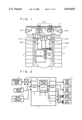
- FIG. 1 is a schematic view of an outline structure of a mobile robot 1 provided with a controller according to a first embodiment of the present invention.
- the robot 1 operates forward running, backward running, pausing, and turning motions with a pair of caterpillar treads 3, 4 mounted on right and left sides, respectively, of the body 2 of the robot 1, and controlled therefrom.
- Each tread 3, 4 is joined to a driving motor (not shown).
- the turning motion includes: a pivot turn, wherein one of the caterpillar treads 3, 4 is driven, while the other of the caterpillar treads 3, 4 is halted; and a swivel turn, wherein each of the two caterpillar treads 3, 4 are driven away from each other in opposite directions.
- the body 2 has a bumper 5 mounted to the front thereof.
- the bumper 5 is accompanied by a contact sensor (now shown) which senses a pressure upon touching an obstacle and thus, detects the presence of the obstacle.
- the robot 1 also includes eight supersonic sensors for detecting an obstacle without contact, as follows: sensors 6R and 6L mounted on the front right and left side, respectively; sensors 6ML and 6MR mounted on the left and right front ends, respectively; sensors 6DL and 6DR mounted on the front left and right lower side, respectively; and sensors 6SL and 6SR mounted on the left and right sides, respectively, of the robot 1.
- Those sensors are preferably of a supersonic type, but may be of any other type, such as optical sensors.
- the sensors 6R, 6SR, 6MR, and 6DR detect obstacles on the right side of the body 2, while the sensors 6L, 6SL, 6ML, and 6DL detect obstacles on the left side of the body 2.
- the detection signals from the right and left side sensors produce the parameters for rotation of the intra-side and the opposite side treads 3, 4, respectively.
- the eight sensors 6R, 6L, 6MR, 6ML, 6SR, 6SL, 6DR, and 6DL will be simply called a supersonic sensor group 6 when all are inclusively referred to.
- the sensors 6DR, 6DL, 6MR, and 6ML are connected to a first electronic control unit or ECU 1a
- the sensors 6SR and 6SL are connected to a second electronic control unit or ECU 2a
- the sensors 6R and 6L are connected to a third electronic control unit or ECU 3a, respectively.
- the ECUs all are connected to the controller 7, which will be described later, and the ECU's are all arranged to control the driver circuit for the sensor group 6 and the inputting and outputting of the detection signals from the sensor group 6.
- additional sensors are provided for detecting the number of revolutions of the treads 3, 4.
- the revolution sensors may be implemented, for example, by encoders directly linked to the two driving motors. A pulse output of each encoder is used as indicative of the number of revolutions.
- the controller 7 includes a central processing unit or CPU 8 and a digital input 9, which is connected to the supersonic sensor group 6, via a supersonic sensor driver circuit 16 (including the first through the third ECUs 1a, 2a and 3a), for controlling the input and output of sensor signals.
- the digital input 9 is connected to a contact sensor 5A, mounted on the bumper 5, and to motor revolution sensors (encoders) 10 for the motors driving the left and right treads 3, 4, as well as the supersonic sensor group 6. Accordingly, the detection signals of the supersonic sensor group 6, the contact sensor 5A, and the revolution sensors 10 are transmitted via the digital input 9 to the CPU 8.
- the CPU 8 is connected via a digital output 11 to a right tread (electromagnetic) brake 12, a left tread (electromagnetic) brake 13, a right tread motor 14 (referred to as a right motor), and a left tread motor 15 (referred to as a left motor).
- Instruction signals determined through the respective processes in the CPU 8, are thus supplied via the digital output 11 to the right tread brake 12, the left tread brake 13, the right motor 14, and the left motor 15.
- the right motor 14 and the left motor 15 are fed with the instruction signals for steering.
- the instruction signals for motor revolution speed from the CPU 8 are transferred via a digital-to-analog or D/A converter 17 to the right motor 14 and the left motor 15.
- the CPU 8 is responsive to the inputs from the supersonic sensor group 6 and the contact sensor SA (referred all-inclusively to as "sensors” hereinafter) for determining the action of a drive system including the right motor 14 and the left motor 15.
- sensors referred all-inclusively to as "sensors” hereinafter
- the forward running, backward running, pausing, and turning motions of the robot are independently controlled, as the functions of their corresponding modules, by the CPU 8. While the processes of inputs from the sensors and the generation of motion schemes are being conducted constantly, only the forward running motion is enabled in a normal mode with the swivel turn, pausing, and backward running motions maintained in a sleep state.
- the turning motions, except for the swivel-turns, are controlled by a forward running control module.
- the CPU 8 includes a motion scheme selector 18 for assigning the robot to do one of a number of predetermined motions in conditioned response to the inputs from the sensor group 6.
- FIG. 3 is a schematic view showing a system of process actions in the motion scheme selector 18.
- the motion scheme selector 18 has a multi-stage arrangement connected to the sensors 6 and 5A for generating action schemes and their requests in response to the outputs of the sensors.
- the motion scheme selector 18 selects one of the requests as its instruction signal.
- the instruction signal thus selected is fed to the drive system 19 (an actuator) for controlling the right tread brake 12, the left tread brake 13, the right motor 14, the left motor 15 and others.
- the instruction signals of the action scheme generated in response to the outputs of the sensors are accumulated and used in combination to demonstrate the comprehensive action of the robot.
- the first embodiment is designed for not directly performing the action schemes generated in response to the outputs of the sensors, but instead for ranking the action schemes by their priority under predetermined rules and then, performing a sequence of the action schemes starting from the one having the highest priority.
- FIG. 4 is a block diagram showing a process of motion detection in the first embodiment.
- a highest priority scheme which is to prevent a collision against a wall, is selected by a selector 20 from the action schemes AP1, AP2, . . . Apn.
- the highest priority action scheme in the first embodiment is to run backward.
- the second highest priority is to swivel at the site and the pivot turn, sharp turn, and slow turn follow in the order listed.
- the pivot turn, sharp turn, and slow turn are categorized as part of the forward running motion and are distinguished from each other by the difference of the speed between the left and right treads 3, 4.
- the action scheme when the action scheme is selected for turning slowly at a moderate speed to the right with an angle ⁇ , the scheme driving the right tread 3 at V1 rpm and the left tread 4 at V2 rpm, wherein V2>V1, is executed.
- the priority for each action scheme is determined in response to the outputs of the supersonic sensor group 6 and hence, a stop control is excluded on the basis of the obstacle detection output of the contact sensor.
- the robot runs backwards for a predetermined duration of time and in general, the backward running is promptly shifted to the swivel turn.
- the two motors 14, 15 receive the same instruction of revolutions per minute or rpm. It is preferable, for improving the accuracy of the forward running, to compensate the instructions for the treads 3, 4, on the basis of the output pulse signals from the revolution sensors 10, so that the left and right motors 14, 15 rotate at the same speed.
- the pausing motion is conducted by changing the revolution speed to zero and actuating both the right and left tread brakes 12, 13. If necessary, regenerative braking may be used in the pausing motion.
- a random running which is a basic running pattern of the robot 1.
- the robot 1 usually runs straight forward in an area A defined by boundaries or walls B as shown in FIGS. 5A and 5B.
- the robot 2 reaches at a set distance from one of the walls B, it pauses and turns through a predetermined angle (or may be moved backward a distance before turning).
- the robot 1 starts again running in a straight line towards the other wall B.
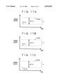
- the angle ⁇ of turning (FIG. 5B) in the proximity of the wall B may be determined at random selection in each turning motion.
- the inventors of the present invention have found through a series of simulations that there is an optimum turning angle ⁇ for allowing the robot 1 to run, not into the regions where the robot 1 has already passed, but across different regions to cover more portions of the area A.
- the optimum angle ⁇ is 135 degrees.
- the random running pattern with the turning angle ⁇ of 135 degrees will hereinafter be referred to as a fine-tuning random running pattern.
- a combination of the fine-tuning random running pattern and a spiral pattern running motion further improves the efficiency of working operation, when the random running (preferably, the fine-tuning random running with 135-degree turning) has been repeated a predetermined number of times, and the running is switched into a spiral motion.
- the random running preferably, the fine-tuning random running with 135-degree turning
- spiral/random running pattern Such a combination of the random running and the spiral running will hereinafter be referred to as spiral/random running pattern.
- the robot 1 is first placed at an appropriate spot in the area A. It is assumed that the area A has a rectangular shape defined by four walls B. The initial placing of the robot 1 is arbitrary. The robot 1 then starts running in a spiral pattern as shown in FIG. 6A. In the spiral running, the radius of circling is gradually increased in turns. This motion is controlled by a decision which is different from those for the forward running, the swivel turning, and backward running and will be explained later in more detail referring to FIG. 14. In brief, the speeds of the two treads 3, 4 or the revolution speeds of the two motors 14, 15 are calculated so that there are no gaps between any two adjacent circling tracks of the robot 1.
- the speeds of the two treads 3, 4 or the revolution speeds of the two motors 14, 15 are then updated for increasing the radius of circling in turns.
- the robot 1 comes close to one of the walls B and its arrival at substantially a predetermined distance from the wall B is detected with the supersonic sensor group 6. This allows the robot 1 to stop the spiral running and start a (preferably fine-tuning) random pattern running for traveling to a location where another spiral running is to be commenced (FIG. 6B).
- the shaded areas in FIGS. 6B and 6C represent the trace of the robot 1 or the regions which have been covered by the running of the robot 1.
- the intermediate action from the cancelling of the current spiral running and to the starting of another spiral running is as follows.
- the turning motion explained with reference to FIGS. 5A and 5B, starts.
- the robot 1 immediately stops its forward running, moves backward a predetermined distance if required, and performs a swivel turn through 135 degrees (or any other desired angle) before resuming a forward running to move away from the wall B.
- the robot 1 may be turned sharply with a smaller angle to steer clear of the wall B.
- the robot 1 when the robot 1 has turned away from the wall B, run forward, and arrived close to another wall B, its running direction will be changed by conducting the backward running and the swivel, pivot or simple turning. After the turning at the wall B is repeated a predetermined number of times N, the robot 1 runs away from the wall B where the latest turning motion has been performed for a specific duration of time T (or by a specific distance D) and the robot 1 stops its forward running motion. Then, the robot 1 again starts another spiral pattern running motion (FIG. 6C) and the above-mentioned actions are repeated thereafter.
- the distance D from the latest wall B is substituted by the time T.
- a designer or an operator of the robot 1 may, however, select either the distance D or the time T as a parameter for use in the controlling operation.
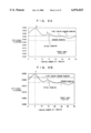
- FIGS. 7A and 7B are graphs showing the relationship between a working time and a progress of the work or a coverage of the target area conducted by a robot 1 in the simulations of the present invention.
- the vertical axis represents a rate (%) of the target area covered by running of the robot 1 and the horizontal axis is a working time from the start.
- the size and shape of the robot 1 is equivalent to a circle of 20 cm in diameter and running speed of the robot 1 is 13 cm/second.
- the target area is a square having dimensions of 4.2 m by 4.2 m in FIG. 7A and is a rectangle having dimensions of 4.2 m by 8.4 m in FIG. 7B.
- a coordinates pattern running is defined as a running motion along a path predetermined on a coordinate plane so that the robot 1 can cover the entirety of the target area, in which the area coverage rate is increased linearly proportional to an elapsed time.
- the other pattern running motions including the spiral/random pattern running, exhibit an attenuating increment of the area coverage and may find it very difficult to cover the entirety of the area.
- the area coverage of 80% is acceptable
- three of the pattern running motions, except for the coordinates pattern running motion are compared in the efficiency of 80% coverage per a spent time. It is apparent that the spiral/random pattern running motion covers 80% of the target area in the shortest time.
- the number of turning times N and the forward running time T must be previously set to desired values. If the number of times N is too small, the spiral running to be resumed is too close to the preceding spiral running area and hence, an overlap region increases and the work efficiency declines. On the contrary, when N is too large, the time T (or the distance D) of forward running is increased too much and thus, the working efficiency is lowered. If the time T is excessively short or long, the spiral running resumes near the latest wall B and may quickly come close to another wall B so that the working efficiency declines.
- Optimum lengths of time T are found through experimental simulations, as shown in FIGS. 8A and 8B.
- the vertical axis represents the working efficiency and the horizontal axis is the time T (seconds) after the swivel turning motion.
- the working efficiency is defined as a coverage (%) of the target area per second and is calculated on the basis of the time spent for covering 80% of the target area (FIGS. 7A and 7B).
- the area to be covered by the robot 1 is a 4.2 m ⁇ 4.2 m square, as in FIG. 8A, and a 4.2 m ⁇ 8.4 m rectangle, as in FIG. 8B.
- the size and shape of the robot 1 is a circle of 20 cm in diameter and the running speed of the robot 1 is 13 cm/second.
- FIGS. 8A and 8B there are two (peak) points P and Q where the working efficiency is extreme for the time T. It is hence desired that the time T is determined at the point P where the working efficiency is at a maximum in a shorter time T. For the purpose of comparison, levels of the working efficiency in the random pattern and fine-tuning random pattern running motions are also shown.
- FIGS. 9A and 9B illustrate optimums of the number of turning times N found through the simulations.
- the vertical axis represents the working efficiency and the horizontal axis is the number of turning times N.
- the size of a target area, the projected area of the robot 1, and the running speed of the robot 1 are identical to those shown in FIGS. 8A and 8B.
- (peak) optimum points R, S, T . . . of the working efficiency are specified as the number of turning times N is varied.
- the number of turning times N is five, the working efficiency is maximum in each case where the target area is large or small.
- levels of the working efficiency in the fine-tuning random pattern and random pattern running are shown.
- Step S100 stands by to receive a request from the supersonic sensor group 6 (or the supersonic sensor driver circuit 16).
- the procedure goes to Step S110 where it is determined whether or not the request indicates transmission of supersonic waves or more specifically, whether the CPU 8 is informed of transmission of supersonic waves from the supersonic sensor 6.
- the procedure moves to Step S120 for presetting the counter with a predetermined value and starting countdown of the counter.
- the predetermined value which is preset, is indicative of a predicted longest duration of time in which reflected waves will be received by the supersonic sensor 6.
- Step S130 It is then determined at Step S130 whether or not a request of signal reception is issued, or more specifically, whether the supersonic sensor 6 receives the reflected waves. If the request of signal receipt is not issued, the procedure goes to Step S140 where whether or not the time preset has expired is checked, or more specifically, whether the counter has counted down to zero. When the preset time has not expired, the waiting for the request of the signal receipt continues until the time has expired. When it is judged at Step S130 that the request of signal receipt has been released, the procedure moves to Step S150 for saving a current count of the counter value. When the count has been saved, the counter is cleared at Step S170.
- Step S160 If the request of signal receipt is not received before the time has expired, the current count is saved as 0 at Step S160 and the counter is cleared at Step S170.
- Step S180 majority operation may preferably be carried out for improving the reliability of the count saved at Step S150. The majority operation will be explained later in more detail referring to FIG. 17.
- the count saved during the processing of inputs from the supersonic sensors 6 is referred to as a distance count hereinafter.
- FIG. 11 is a flowchart of processing an input from the contact sensor 5A.
- Step S80 When it is determined at Step S80 that the detection signal from the contact sensor 5A is received, the procedure goes to Step S90 where a command for stopping the running of the robot 1, or an instruction for shifting the revolution speeds of the two motors 14, 15 to zero, is delivered and simultaneously, the right and left brakes 12, 13 are actuated.
- the processing of inputs from the contact sensor 5A may be executed by the timer interruption at intervals of, for example, 10 milliseconds.
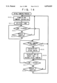
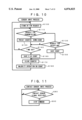
- Step S1 an instruction for starting the spiral running is given at Step S1.
- the controlling of the spiral running will be described later in more detail referring to FIG. 14.
- Step S2 the distance count, which is a result of the processing of inputs of the supersonic sensors, is requested.
- Step S3 the processing of an input from the contact sensor is carried out at Step S3 (actually, it is done by the timer interruption, as mentioned above).
- Step S4 it is determined whether the spiral running is under way or not.
- Step S4 judges yes.
- the procedure advances to Step S5 where it is determined whether or not the spiral running is to be continued or not.
- Step S5 for determining the continuation of the spiral running incorporates judging, on the basis of the distance count saved in the supersonic sensor inputs processing, whether or not the robot 1 is close to the predetermined distance from any wall B, or whether or not the current spiral running has to be cancelled and moved to a different location where another spiral running is started.
- Step S6 it is decided from the result of Step S5 whether or not the spiral running is cancelled. If not, the procedure returns to Step S2.
- Step S6 When the decision is affirmative at Step S6, the procedure goes to Step S8 for selecting the succeeding motion.
- the backward running commonly follows. At that time, the robot 1 is so close to the wall B that its normal turning may easily result in collision with the wall B. Therefore, the backward running is generally selected first, then it is commonly followed by the swivel turn and the (straight) forward running.
- Step S9 When the backward running is selected at Step S8, the procedure moves to Step S9 where it is determined whether or not the current motion is backward. The motion is not backward immediately after the spiral running is cancelled and then, it is judged not.
- Step S10 follows where the pausing motion of the robot is called for a moment (in 20 to 30 ms) and the procedure goes to Step S11. If the current motion is judged to be backward at Step S9, the procedure skips Step S10 and moves to Step S11.
- the backward running process is requested to be commenced at Step S11 as will be explained later in more detail.
- the backward running takes over the spiral running and "no" is established at Step S4 before the procedure goes to Step S7. Since the spiral running has been cancelled, the decision at Step S7 is used at Step S8 for selection of the succeeding motion.
- the succeeding motion is selected or decided according to the distance count produced by the supersonic sensor group 6 (a succeeding motion determination).
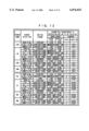
- the succeeding motion determination incorporates selection of the succeeding motion for the robot through examining run parameters listed in the run parameter table of FIG. 13. Selections of the parameters in the table of FIG. 13 are designated corresponding to the detection outputs of the sensors which indicate the distances to the wall and are transmitted for starting a desired motion.
- the parameters include the speeds of the two treads, the degree of turning, and the direction of turning.
- the speed of each tread of the robot 1 is classified into four levels: very low speed (0.5 km/h), low speed (1.0 km/h), moderate speed (2 km/h), and high speed (3 km/h).
- the turning degree is classified into four levels: slow turn (through 30 degrees, Level 3), sharp turn (through 60 degrees, Level 2), pivot turn (turn on pivot with one tread held, Level 1), and swivel turn (two treads turned in opposite directions each other, Level 0).
- the turning motion is also categorized into the left turn and right turn.
- the speed parameter for each tread of the robot 1 is categorized in two categories, as follows: speed of the sensor-side or intra-side tread and speed of the opposite-side or other tread. For instance, two parameters of the tread speed for the (right) motor of the right tread and the (left) motor of the opposite or left tread are provided on the basis of the detection output of the sensor 6R on the right side. Since a number of the parameters are usually generated corresponding to the detection outputs of all the sensors 6, their selection to be actually used is governed by a predetermined rule.
- the table of FIG. 13 has a general rule, according to the present invention, which gives the priority to the slower speeds with an exception in that the very low speed is selected when the "pause" parameters are assigned to both of the motors 14, 15.
- the "low speed” parameter is assigned to the intra-side or right motor and the "pause” parameter is assigned to the opposite-side or left motor.
- the control to be activated is a turning motion in which the turning level parameter is "1" for the pivot turn and the turning direction parameter is "left".
- the parameters of "moderate speed” is given for the intra-side or left motor, “very low speed” is given for the opposite-side or right motor, “turning” is given for the control to be activated, “2” is given to the turning level, and “right” is given to the turning direction.
- the distance of 1.5 m to 2 m from the distance count of the right sensor 6R defines the "moderate speed” parameter for the intra-side or right motor and the "low speed” parameters for the opposite or left motor.
- the distance of 1.5 m to 2 m from the distance count of the left sensor 6L defines the "moderate speed” parameter for the left motor and the "low speed” parameters for the right motor.
- the detection outputs of the two sensors 6L and 6R are always the same. This causes the robot 1 to slow down its running speed as it comes close to the wall, stop the running at least, then perform the backward motion and the swivel turn, and finally, run away from the wall B.
- Step S12 It is determined at Step S12 whether or not the swivel turn is under way. In the beginning, it is judged that the swivel turn is underway and the procedure advances to Step S13, for instance, pausing (for about 20 to 30 ms). Then, an instruction for starting the swivel turn is given at Step S14. In succeeding cycles of the procedure, when it is judged that the swivel turn is under way at Step S12, the procedure goes to Step S15 for starting an escape control mode.
- the robot 1 may find it difficult to escape from the corner with only a common combination of the backward running motion and the swivel turn.
- the escape control mode is selected in the course of the swivel turn.
- the escape control mode is not closely related to the present invention and will not be explained in more detail.
- the teaching on the escape control in the specification of Japanese Patent Application No. HEI 9-42879 is referred to and is hereby incorporated into this specification by reference.
- Step S8 When the forward running motion is selected at Step S8 after the swivel turn through a specific angle (e.g. of 135 degrees), the procedure goes to Step S16 and Step S17 for instant pausing (for about 20 to 30 ms), Step S18 for prevention of hunting, and Step S19 for issuing an instruction of starting the forward running motion.
- the robot 1 runs straight forward and when the robot comes close to the predetermined distance from another wall, the robot's succeeding motion is determined from the distance count of the sensors.
- the prevention of hunting is not closely related to the present invention and will not be explained in more detail.
- the teaching on the hunting prevention in the specification of Japanese Patent Application No. HEI 9-42878 is referred to and is hereby incorporated by reference into this specification.
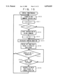
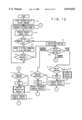
- the spiral running of the robot 1 is commenced when the robot begins to run for working operation as described above with reference to FIG. 12, and when, as mentioned previously with FIGS. 6A to 6C, the time T has elapsed after the last of the number N times of the swivel turnings conducted during the random running in which the robot 1 changes its running direction upon detecting the wall.
- the spiral running process is started as commanded by the operator at Step S1 (FIG. 12).
- the commencement of the spiral running is requested by an instruction produced in a swivel turning process module (at Step S33 in FIG. 15) after the swivel turn has been carried out number N of times.
- the following description concerns the spiral running started by the instruction to commence which is produced in the swivel turning process module.
- Step S20 stands by for receiving the instruction to start the spiral running from the swivel turn control module (Step S33). More particularly, the procedure stands by the issuance of the instruction from the swivel running control module after the swivel turn has been repeated a number N of times. Upon receiving the instruction, the time is set to the time T (e.g. 26 seconds), from the last of the number N of swivel turns to the start of the spiral running, and is started at Step S21. The instruction for starting the spiral running is released at substantially the moment when the last or N-th swivel turning motion starts up (at Step S33 in FIG. 15).
- T e.g. 26 seconds
- the time T at Step S21 therefore, comprises a period for the backward running motion just before the swivel turn and a period for the swivel turn itself (Step S35 in FIG. 15). It is then examined at Step S22 whether or not the time T is elapsed. When so, the procedure advances to Step S24. Before the time T ends up, it is examined at Step S23 whether or not the cancellation of the operation is requested or not. If the cancellation of the operation is requested before the end of the time T, the procedure moves back to Step S20 for stand-by.
- Step S24 it is judged whether or not the spiral running motion is finished.
- the distance from the robot 1 to the wall B or obstacle, which is found on the basis of the distance count of the sensors, is less than the predetermined distance, or when the detection output of the contact switch 5A produces a stop signal, it is then judged yes that the spiral running motion is finished at Step S24. Then, the procedure returns back to Step S20. If it is judged not that the spiral running motion is not finished, Step S25 follows.
- Step S25 the speeds of the two treads 3, 4 for determining the size of a spiral or the radius of the turning motion are calculated and set. Since both of the motors 14, 15 are loaded with signals for realizing the calculated speeds of the two treads 3, 4, the spiral running motion is realized.
- Step S26 the time t for updating the speeds of the two treads 3, 4 is calculated to smoothly enlarge the spiral running motion and is set in the timer which is then started up. It is determined at Step S27, whether or not the time t has passed. When the time t has passed, the procedure returns back to Step S24. At Step S28, it is also determined whether or not the cancellation of the operation is requested. When the cancellation of the operation is not requested, Steps S27 and S28 are repeated until the time t is ended. If the cancellation of the operation is requested, the procedure goes back to step S20 and stays in stand-by.
- Step S30 stands by for receiving the instruction of starting the swivel turning process.
- the current number n of the swivel turn times (referred to as the swivel times hereinafter) is incremented (+1). It is determined at Step S32, whether or not the swivel times n catches up to the predetermined number N. Since the swivel times n is initialized to 0, the swivel times n becomes 1 in the first routine. If the swivel times n are judged not to catch up to the predetermined number N at Step S32, the procedure skips Step S33 and Step S34 and jumps to Step S35.
- Step S35 the duration of turning is calculated. Since the turning duration depends on the turning angle, it is determined in this embodiment in relation to the angle of 135 turning degrees specified for the fine-tuning random pattern running.
- Step S36 an instruction is made for driving the left tread 3 and the right tread 4 in opposite directions to each other.
- the rotating directions of the two treads 3, 4 are determined on the basis of the "turning direction" parameters shown in FIG. 13.
- Step S37 whether or not the cancellation is requested. If the cancellation is requested, the procedure returns back to Step S30.
- Step S38 it is judged at Step S38 whether or not the swivel turn is to be finished. When the swivel turn is to be finished, the procedure advances to Step S39 where an instruction is made for driving both the treads 3, 4 in the forward direction to shift the running mode to the basic straight forward running motion.
- Step S34 the number of swivel times n used for judging a repeat of the swivel turn is cleared to zero. This is followed by Steps S35 to S39 for finishing the cycle of the motor Nth swivel turn and return to Step S30 for staying in stand-by until the next available instruction is received.
- Step S33 the spiral running motion starts after the time T has elapsed (FIG. 14). Thereby, the two control operations for the spiral running motion and the swivel turn will never overlap each other.
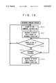
- Step S50 stands by for receiving an instruction.
- Step S51 an instruction is issued for driving the two treads 3, 4 in the backward direction. It is then determined at Step S52, whether or not the cancellation of the operation is released. When so, the procedure returns back to Step S50. If not, the procedure goes to Step S53 where it is determined whether or not the duration for the backward running is ended. When the backward running has been finished, the procedure moves to Step S54 for driving the two treads 3, 4 in the forward direction.
- the majority rule for selection of the sensor output in processing the outputs of the supersonic sensors (S180 in FIG. 10) will now be explained.
- the use of the majority rule is preferable for improving the reliability of acquired data (of the distance count) which may be susceptible to the environment of the supersonic sensor group 6.
- the majority rule when current data is acquired, the majority rule is applied to the current data and two old data to determine if the current data is available as new data.
- a margin m is provided above and below the preceding data MID, respectively.
- the current data NEW is within the margin m, it is judged as a normal detection signal and used as the distance count.
- the current data NEW is outside of the margin m as shown in FIG. 17B, it is further determined whether or not the data OLD preceding the preceding data MID is within the margin m.
- the preceding data MID is accepted as the normal detection signal and used as a new distance count in place of the current data NEW.
- the current data NEW is used as the distance count because these three data are too much separated from each other and hardly identified as the normal detection signal.
- the present invention allows a mobile robot to run throughout almost the entirety of a given area only by traveling in a combination of standardized spiral running and linear (random) running motion until the robot detects a boundary of the area or an obstacle.
- the optimum conditions for running throughout the area at higher efficiency are determined through a series of simulations and used for controlling the motion of the robot.
- the parameters for steering the robot are prepared based only on the detection outputs of their respective sensors mounted on both the left and right sides of the robot and used for determining by a priority rule the actual parameter to control the motion of the robot.
- the control units connected to the sensors on both the left and right sides are activated for calculating the provisional parameters exclusively of the other parameters and hence, are less complicated in their construction.
Abstract
A robot is provided to run so that a trace of the robot efficiently covers a given area according to the detection of a boundary of the area. A spiral pattern running, wherein a radius of the spiral is gradually increased, is started at a desired location in the area and is paused upon the detection of a boundary wall by sensors. Then, a random pattern running, which includes turning to depart from the wall and running forward, is conducted. After the turning has been repeated a predetermined number of times through simulations, the spiral pattern running is resumed at a location spaced from the last turning spot by a predetermined distance or a predetermined length of running time.
Description
1. Field of the Invention
The present invention generally relates to a mobile robot steering method and a controlling device for a mobile robot and more particularly, to a method which allows the mobile robot to run throughout almost the entirety of a given area in a shorter period of time and a device for implementing the same.
2. Description of the Related Art
Mobile robots, including a cleaner robot, a mower robot, a plasterer robot, and an agricultural sprayer robot, are known which automatically run throughout a given area for accomplishment of an imposed task. For example, a cleaner robot, is disclosed in Japanese Patent Laid-open Publication No. HEI 5-46246 (hereinafter "JP '246"). The cleaner robot of JP '246 first runs about in a target room to be cleaned to map out a running or cleaning area through detection of the size and shape of the target room and the locations of obstacles in the room. Coordinates data, produced by the mapping, are then used for a mobile robot to clean the room while running in either a zigzag pattern or a spiral pattern in which the radius of circling is gradually decreased after every turn. The robot includes contact sensors and supersonic sensors for detecting walls around the robot to determine the robot's route. The robot also includes a distance meter for measuring the distance traveled in order to know the end of the circling motion. Another mobile robot, for running around throughout the whole area of a given floor, is disclosed in Japanese Patent Laid-open Publication No. HEI 5-257533 (hereinafter "JP '533").
Such conventional mobile robots, as shown in JP '246 and JP '533, are generally provided with a number of sensors. The outputs of the sensors are used for acquiring the data of an area to be traveled and determining the operations to be performed for running through. More particularly, the outputs of the sensors are constantly transferred to a central controlling unit, which in turn determines the controlling action for steering the robot at high accuracy on the basis of the sensor outputs. Driving actuators, such as motors, are controlled on the basis of these determinations.
When the central controlling unit handles the outputs of all of the sensors, the system of the central controlling unit should be sophisticated and the central controlling unit's processing speed will be lowered. Such a lower processing speed may retard and thus, take an averting action, when encountering an obstacle such as a wall. Also, time for mapping, teaching, and settings of relevant thresholds and initial values are required, for various kinds of controls and skills for the settings.
Accordingly, conventional mobile robots are so bulky in size, heavy in weight, and costly that the applications thereof will be limited. Examples of the limited applications are, for instance, as transporting robots and as cleaning robots in plants.
Not all robots have to run throughout the entirety of a target area at a higher accuracy, but some robots are allowed to run throughout the area with a considerable degree of accuracy. The routes and directions of these robots may not be critical. In some cases of a cleaning robot, for example, the area to be cleaned does not always have to be covered in its entirety, but rather some of the area can remain uncleaned. Depending on the requirements of some mower robots, the mower robots must produce highly neat traces of mowed area and the other mower robots are expected to perform a mowing operation only at a substantial level.
It is the object of the present invention to provide a mobile robot steering method and a device for the same in which a robot with a simple construction is caused to run throughout almost the entirety of a target area to be covered.
According to the present invention, a mobile robot, while detecting the boundary of an area to be covered with its sensors, performs a spiral pattern running motion which starts from any desired location in the area and which has a radius that is gradually increased. When the distance of the robot from the boundary is smaller than a preset value, the spiral pattern running motion is cancelled and a random pattern running motion is started. The random pattern running motion includes first turning from the forward direction by a predetermined angle to run away from the boundary, running straight forward, then repeating the turning motion and the straight forward running motion whenever the boundary is detected. When the turning motion has been repeated a predetermined number of times, the spiral pattern running motion is started again at a location spaced by a predetermined distance from the last turning spot or at a location to which the robot has run straight for a predetermined duration of time from the last turning location.
The number of times for repeating the turning motion, before the spiral pattern running motion, and the specific distance or time of straight running, from the last turning motion to the resuming of the spiral pattern running motion, may be determined through a series of simulations so that the duration of time, required for running throughout almost a desired percentage of the area, is minimized. The angle for the turning motion may preferably be 135 degrees with respect to the forward direction.
A controller for a mobile robot, according to the present invention, in which the direction of running is determined by the direction of rotation and the speed of rotation of both left and right wheels of the robot, comprises: either a right side obstacle sensor and a left side obstacle sensor or sensors mounted on the right front and the left front of a main body of the robot; means for generating running motion parameters, in accordance with the distances to obstacles detected by the right and left side sensor(s), which parameters are independent of each other; and means for determining the direction and speed of rotation of each of the left and right motors on the basis of the running motion parameters selected out of at least two of the generated running motion parameters by a predetermined rule of priority. The running speed of the robot may preferably be lowered in steps, in proportion to the distance detected from the obstacle.
FIG. 1 is a schematic view showing a construction of a robot according to a first embodiment of the present invention;
FIG. 2 is a block diagram of a hardware structure of a controller according to the first embodiment of the present invention;
FIG. 3 is a schematic diagram showing the process system for selecting a motion scheme;
FIG. 4 is a block diagram showing the selection of the motion scheme;
FIGS. 5A and 5B are schematic views showing a basic pattern running motion for the robot according to the present invention;
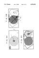
FIGS. 6A, 6B and 6C are schematic views showing a spiral pattern running motion for the robot according to the present invention;
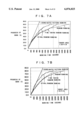
FIGS. 7A and 7B are diagrams of a result of simulation showing the relationship between time and progress of work using various parameters of the running pattern motion;
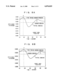
FIGS. 8A and 8B are diagrams of a result of simulation showing the relationship between working efficiency and amount of running time T;
FIGS. 9A and 9B are diagrams of a result of simulation showing the relationship between working efficiency and the number of times of turning or revolving motions N;
FIG. 10 is a flowchart of processing inputs from supersonic sensors;
FIG. 11 is a flowchart of processing inputs from contact sensors;
FIG. 12 is a flowchart showing motion selection or determination in the spiral pattern running motion;
FIG. 13 is a run parameter table showing the relationship between run parameters and outputs of the sensors;
FIG. 14 is a flowchart showing control of the spiral pattern running motion;
FIG. 15 is a flowchart showing control of a swivel turn motion;
FIG. 16 is a flowchart showing control of a backward running motion; and
FIGS. 17A, 17B, and 17C are schematic diagrams showing control of selection of sensor signals.
The present invention will be described in more detail referring to the accompanying drawings. FIG. 1 is a schematic view of an outline structure of a mobile robot 1 provided with a controller according to a first embodiment of the present invention. As shown, the robot 1 operates forward running, backward running, pausing, and turning motions with a pair of caterpillar treads 3, 4 mounted on right and left sides, respectively, of the body 2 of the robot 1, and controlled therefrom. Each tread 3, 4 is joined to a driving motor (not shown). The turning motion includes: a pivot turn, wherein one of the caterpillar treads 3, 4 is driven, while the other of the caterpillar treads 3, 4 is halted; and a swivel turn, wherein each of the two caterpillar treads 3, 4 are driven away from each other in opposite directions. The body 2 has a bumper 5 mounted to the front thereof. The bumper 5 is accompanied by a contact sensor (now shown) which senses a pressure upon touching an obstacle and thus, detects the presence of the obstacle.
The robot 1 also includes eight supersonic sensors for detecting an obstacle without contact, as follows: sensors 6R and 6L mounted on the front right and left side, respectively; sensors 6ML and 6MR mounted on the left and right front ends, respectively; sensors 6DL and 6DR mounted on the front left and right lower side, respectively; and sensors 6SL and 6SR mounted on the left and right sides, respectively, of the robot 1. Those sensors are preferably of a supersonic type, but may be of any other type, such as optical sensors. The sensors 6R, 6SR, 6MR, and 6DR detect obstacles on the right side of the body 2, while the sensors 6L, 6SL, 6ML, and 6DL detect obstacles on the left side of the body 2. The detection signals from the right and left side sensors produce the parameters for rotation of the intra-side and the opposite side treads 3, 4, respectively.
For simplicity of description, the eight sensors 6R, 6L, 6MR, 6ML, 6SR, 6SL, 6DR, and 6DL will be simply called a supersonic sensor group 6 when all are inclusively referred to. The sensors 6DR, 6DL, 6MR, and 6ML are connected to a first electronic control unit or ECU 1a, the sensors 6SR and 6SL are connected to a second electronic control unit or ECU 2a, and the sensors 6R and 6L are connected to a third electronic control unit or ECU 3a, respectively. The ECUs all are connected to the controller 7, which will be described later, and the ECU's are all arranged to control the driver circuit for the sensor group 6 and the inputting and outputting of the detection signals from the sensor group 6.
In addition to the above-mentioned obstacle sensors, additional sensors (not shown) are provided for detecting the number of revolutions of the treads 3, 4. The revolution sensors may be implemented, for example, by encoders directly linked to the two driving motors. A pulse output of each encoder is used as indicative of the number of revolutions.
A hardware arrangement of the controller 7 in the first embodiment will now be described referring to the block diagram of FIG. 2. The controller 7 includes a central processing unit or CPU 8 and a digital input 9, which is connected to the supersonic sensor group 6, via a supersonic sensor driver circuit 16 (including the first through the third ECUs 1a, 2a and 3a), for controlling the input and output of sensor signals. Also, the digital input 9 is connected to a contact sensor 5A, mounted on the bumper 5, and to motor revolution sensors (encoders) 10 for the motors driving the left and right treads 3, 4, as well as the supersonic sensor group 6. Accordingly, the detection signals of the supersonic sensor group 6, the contact sensor 5A, and the revolution sensors 10 are transmitted via the digital input 9 to the CPU 8.
The CPU 8 is connected via a digital output 11 to a right tread (electromagnetic) brake 12, a left tread (electromagnetic) brake 13, a right tread motor 14 (referred to as a right motor), and a left tread motor 15 (referred to as a left motor). Instruction signals, determined through the respective processes in the CPU 8, are thus supplied via the digital output 11 to the right tread brake 12, the left tread brake 13, the right motor 14, and the left motor 15. The right motor 14 and the left motor 15 are fed with the instruction signals for steering. Also, the instruction signals for motor revolution speed from the CPU 8 are transferred via a digital-to-analog or D/A converter 17 to the right motor 14 and the left motor 15.
In this arrangement, the CPU 8 is responsive to the inputs from the supersonic sensor group 6 and the contact sensor SA (referred all-inclusively to as "sensors" hereinafter) for determining the action of a drive system including the right motor 14 and the left motor 15. The forward running, backward running, pausing, and turning motions of the robot are independently controlled, as the functions of their corresponding modules, by the CPU 8. While the processes of inputs from the sensors and the generation of motion schemes are being conducted constantly, only the forward running motion is enabled in a normal mode with the swivel turn, pausing, and backward running motions maintained in a sleep state. The turning motions, except for the swivel-turns, are controlled by a forward running control module.
The CPU 8 includes a motion scheme selector 18 for assigning the robot to do one of a number of predetermined motions in conditioned response to the inputs from the sensor group 6. FIG. 3 is a schematic view showing a system of process actions in the motion scheme selector 18. As shown, the motion scheme selector 18 has a multi-stage arrangement connected to the sensors 6 and 5A for generating action schemes and their requests in response to the outputs of the sensors. The motion scheme selector 18 selects one of the requests as its instruction signal. The instruction signal thus selected is fed to the drive system 19 (an actuator) for controlling the right tread brake 12, the left tread brake 13, the right motor 14, the left motor 15 and others. As mentioned above, the instruction signals of the action scheme generated in response to the outputs of the sensors are accumulated and used in combination to demonstrate the comprehensive action of the robot.
The first embodiment is designed for not directly performing the action schemes generated in response to the outputs of the sensors, but instead for ranking the action schemes by their priority under predetermined rules and then, performing a sequence of the action schemes starting from the one having the highest priority. FIG. 4 is a block diagram showing a process of motion detection in the first embodiment. When the action schemes AP1, AP2, . . . APn and their requests have been generated, a highest priority scheme, which is to prevent a collision against a wall, is selected by a selector 20 from the action schemes AP1, AP2, . . . Apn. The highest priority action scheme in the first embodiment is to run backward. The second highest priority is to swivel at the site and the pivot turn, sharp turn, and slow turn follow in the order listed. The pivot turn, sharp turn, and slow turn are categorized as part of the forward running motion and are distinguished from each other by the difference of the speed between the left and right treads 3, 4.
For example, when the action scheme is selected for turning slowly at a moderate speed to the right with an angle θ, the scheme driving the right tread 3 at V1 rpm and the left tread 4 at V2 rpm, wherein V2>V1, is executed. The priority for each action scheme is determined in response to the outputs of the supersonic sensor group 6 and hence, a stop control is excluded on the basis of the obstacle detection output of the contact sensor.
It should be noted that in a backward running of the motion schemes, the robot runs backwards for a predetermined duration of time and in general, the backward running is promptly shifted to the swivel turn. During a normal forward running, the two motors 14, 15 receive the same instruction of revolutions per minute or rpm. It is preferable, for improving the accuracy of the forward running, to compensate the instructions for the treads 3, 4, on the basis of the output pulse signals from the revolution sensors 10, so that the left and right motors 14, 15 rotate at the same speed. The pausing motion is conducted by changing the revolution speed to zero and actuating both the right and left tread brakes 12, 13. If necessary, regenerative braking may be used in the pausing motion.
Patterns of running of the robot according to the present invention, which are combinations of the above motions, will now be explained. The description starts with a random running which is a basic running pattern of the robot 1. In the random running pattern, the robot 1 usually runs straight forward in an area A defined by boundaries or walls B as shown in FIGS. 5A and 5B. When the robot 2 reaches at a set distance from one of the walls B, it pauses and turns through a predetermined angle (or may be moved backward a distance before turning). Then, the robot 1 starts again running in a straight line towards the other wall B. The angle α of turning (FIG. 5B) in the proximity of the wall B may be determined at random selection in each turning motion.
The inventors of the present invention have found through a series of simulations that there is an optimum turning angle α for allowing the robot 1 to run, not into the regions where the robot 1 has already passed, but across different regions to cover more portions of the area A. The optimum angle α is 135 degrees. The random running pattern with the turning angle α of 135 degrees will hereinafter be referred to as a fine-tuning random running pattern.
It has also been found by the inventors of the present invention that a combination of the fine-tuning random running pattern and a spiral pattern running motion further improves the efficiency of working operation, when the random running (preferably, the fine-tuning random running with 135-degree turning) has been repeated a predetermined number of times, and the running is switched into a spiral motion. Such a combination of the random running and the spiral running will hereinafter be referred to as spiral/random running pattern.
The spiral/random running pattern is now explained in more detail. Referring to FIG. 6A, the robot 1 is first placed at an appropriate spot in the area A. It is assumed that the area A has a rectangular shape defined by four walls B. The initial placing of the robot 1 is arbitrary. The robot 1 then starts running in a spiral pattern as shown in FIG. 6A. In the spiral running, the radius of circling is gradually increased in turns. This motion is controlled by a decision which is different from those for the forward running, the swivel turning, and backward running and will be explained later in more detail referring to FIG. 14. In brief, the speeds of the two treads 3, 4 or the revolution speeds of the two motors 14, 15 are calculated so that there are no gaps between any two adjacent circling tracks of the robot 1. The speeds of the two treads 3, 4 or the revolution speeds of the two motors 14, 15 are then updated for increasing the radius of circling in turns. As the spiral of the trace is enlarged, the robot 1 comes close to one of the walls B and its arrival at substantially a predetermined distance from the wall B is detected with the supersonic sensor group 6. This allows the robot 1 to stop the spiral running and start a (preferably fine-tuning) random pattern running for traveling to a location where another spiral running is to be commenced (FIG. 6B). The shaded areas in FIGS. 6B and 6C represent the trace of the robot 1 or the regions which have been covered by the running of the robot 1.
The intermediate action from the cancelling of the current spiral running and to the starting of another spiral running is as follows. When the robot 1 comes close to the wall B and any supersonic sensor 6 detects that the robot 1 is at about a predetermined distance from the wall B, the turning motion, explained with reference to FIGS. 5A and 5B, starts. For example, when the current distance of the robot 1 from the wall B is smaller than the predetermined distance at the moment of the detection of the wall B, the robot 1 immediately stops its forward running, moves backward a predetermined distance if required, and performs a swivel turn through 135 degrees (or any other desired angle) before resuming a forward running to move away from the wall B. Should the current distance of the robot 1 from the wall B at the time of detection be greater than the predetermined distance, the robot 1 may be turned sharply with a smaller angle to steer clear of the wall B.
Similarly, when the robot 1 has turned away from the wall B, run forward, and arrived close to another wall B, its running direction will be changed by conducting the backward running and the swivel, pivot or simple turning. After the turning at the wall B is repeated a predetermined number of times N, the robot 1 runs away from the wall B where the latest turning motion has been performed for a specific duration of time T (or by a specific distance D) and the robot 1 stops its forward running motion. Then, the robot 1 again starts another spiral pattern running motion (FIG. 6C) and the above-mentioned actions are repeated thereafter. For simplicity of description, the distance D from the latest wall B is substituted by the time T. A designer or an operator of the robot 1 may, however, select either the distance D or the time T as a parameter for use in the controlling operation.
FIGS. 7A and 7B are graphs showing the relationship between a working time and a progress of the work or a coverage of the target area conducted by a robot 1 in the simulations of the present invention. The vertical axis represents a rate (%) of the target area covered by running of the robot 1 and the horizontal axis is a working time from the start. It is now noted that the size and shape of the robot 1 is equivalent to a circle of 20 cm in diameter and running speed of the robot 1 is 13 cm/second. The target area is a square having dimensions of 4.2 m by 4.2 m in FIG. 7A and is a rectangle having dimensions of 4.2 m by 8.4 m in FIG. 7B.
In FIGS. 7A and 7B, a coordinates pattern running is defined as a running motion along a path predetermined on a coordinate plane so that the robot 1 can cover the entirety of the target area, in which the area coverage rate is increased linearly proportional to an elapsed time. In comparison, the other pattern running motions, including the spiral/random pattern running, exhibit an attenuating increment of the area coverage and may find it very difficult to cover the entirety of the area. Assuming that the area coverage of 80% is acceptable, three of the pattern running motions, except for the coordinates pattern running motion, are compared in the efficiency of 80% coverage per a spent time. It is apparent that the spiral/random pattern running motion covers 80% of the target area in the shortest time.
The number of turning times N and the forward running time T (or the distance D) must be previously set to desired values. If the number of times N is too small, the spiral running to be resumed is too close to the preceding spiral running area and hence, an overlap region increases and the work efficiency declines. On the contrary, when N is too large, the time T (or the distance D) of forward running is increased too much and thus, the working efficiency is lowered. If the time T is excessively short or long, the spiral running resumes near the latest wall B and may quickly come close to another wall B so that the working efficiency declines.
Optimum lengths of time T are found through experimental simulations, as shown in FIGS. 8A and 8B. The vertical axis represents the working efficiency and the horizontal axis is the time T (seconds) after the swivel turning motion. The working efficiency is defined as a coverage (%) of the target area per second and is calculated on the basis of the time spent for covering 80% of the target area (FIGS. 7A and 7B).
In those simulations, like the previous experiments, the area to be covered by the robot 1 is a 4.2 m×4.2 m square, as in FIG. 8A, and a 4.2 m×8.4 m rectangle, as in FIG. 8B. It is also noted that the size and shape of the robot 1 is a circle of 20 cm in diameter and the running speed of the robot 1 is 13 cm/second. As is apparent from FIGS. 8A and 8B, there are two (peak) points P and Q where the working efficiency is extreme for the time T. It is hence desired that the time T is determined at the point P where the working efficiency is at a maximum in a shorter time T. For the purpose of comparison, levels of the working efficiency in the random pattern and fine-tuning random pattern running motions are also shown.
FIGS. 9A and 9B illustrate optimums of the number of turning times N found through the simulations. The vertical axis represents the working efficiency and the horizontal axis is the number of turning times N. The size of a target area, the projected area of the robot 1, and the running speed of the robot 1 are identical to those shown in FIGS. 8A and 8B. As is apparent, (peak) optimum points R, S, T . . . of the working efficiency are specified as the number of turning times N is varied. When the number of turning times N is five, the working efficiency is maximum in each case where the target area is large or small. For comparison, levels of the working efficiency in the fine-tuning random pattern and random pattern running are shown.
In the simulations for determining the optimum of the time T and the number of turning times N, it has been found that there is no interference with each other between the time T and the number of turning times N. This permits the determination of the optimum of either of the time T or the number of turning times N to be followed by the determination of the optimum of the other of the time T or the number of turning times N. In the first embodiment, first the optimum of the time T is decided and then, the optimum of the number of turning times N is decided.
The action of the controller 7 will now be explained referring to the flowcharts. The explanation starts with processing inputs from the supersonic sensor group 6. As shown in FIG. 10, Step S100 stands by to receive a request from the supersonic sensor group 6 (or the supersonic sensor driver circuit 16). When the request is received, the procedure goes to Step S110 where it is determined whether or not the request indicates transmission of supersonic waves or more specifically, whether the CPU 8 is informed of transmission of supersonic waves from the supersonic sensor 6. When the request demands the transmission of supersonic waves, the procedure moves to Step S120 for presetting the counter with a predetermined value and starting countdown of the counter. The predetermined value, which is preset, is indicative of a predicted longest duration of time in which reflected waves will be received by the supersonic sensor 6.
It is then determined at Step S130 whether or not a request of signal reception is issued, or more specifically, whether the supersonic sensor 6 receives the reflected waves. If the request of signal receipt is not issued, the procedure goes to Step S140 where whether or not the time preset has expired is checked, or more specifically, whether the counter has counted down to zero. When the preset time has not expired, the waiting for the request of the signal receipt continues until the time has expired. When it is judged at Step S130 that the request of signal receipt has been released, the procedure moves to Step S150 for saving a current count of the counter value. When the count has been saved, the counter is cleared at Step S170. If the request of signal receipt is not received before the time has expired, the current count is saved as 0 at Step S160 and the counter is cleared at Step S170. At Step S180, majority operation may preferably be carried out for improving the reliability of the count saved at Step S150. The majority operation will be explained later in more detail referring to FIG. 17. The count saved during the processing of inputs from the supersonic sensors 6 is referred to as a distance count hereinafter.
FIG. 11 is a flowchart of processing an input from the contact sensor 5A. When it is determined at Step S80 that the detection signal from the contact sensor 5A is received, the procedure goes to Step S90 where a command for stopping the running of the robot 1, or an instruction for shifting the revolution speeds of the two motors 14, 15 to zero, is delivered and simultaneously, the right and left brakes 12, 13 are actuated. The processing of inputs from the contact sensor 5A may be executed by the timer interruption at intervals of, for example, 10 milliseconds.
The controlling operation in response to the output signals of their respective sensors is explained. Referring to a general flowchart of FIG. 12, an instruction for starting the spiral running is given at Step S1. The controlling of the spiral running will be described later in more detail referring to FIG. 14. At Step S2, the distance count, which is a result of the processing of inputs of the supersonic sensors, is requested. Then, the processing of an input from the contact sensor is carried out at Step S3 (actually, it is done by the timer interruption, as mentioned above).
This is followed by Step S4 where it is determined whether the spiral running is under way or not. In an initial stage, since the spiral running is enabled by the spiral motion starting instruction (Step S1), Step S4 judges yes. When yes is judged at Step S4, the procedure advances to Step S5 where it is determined whether or not the spiral running is to be continued or not. Step S5 for determining the continuation of the spiral running incorporates judging, on the basis of the distance count saved in the supersonic sensor inputs processing, whether or not the robot 1 is close to the predetermined distance from any wall B, or whether or not the current spiral running has to be cancelled and moved to a different location where another spiral running is started.
In this embodiment, the current spiral running is cancelled when the robot 1 reaches 30 cm or less from the wall B. At Step S6, it is decided from the result of Step S5 whether or not the spiral running is cancelled. If not, the procedure returns to Step S2.
When the decision is affirmative at Step S6, the procedure goes to Step S8 for selecting the succeeding motion. After the spiral running has been cancelled, the backward running commonly follows. At that time, the robot 1 is so close to the wall B that its normal turning may easily result in collision with the wall B. Therefore, the backward running is generally selected first, then it is commonly followed by the swivel turn and the (straight) forward running.
When the backward running is selected at Step S8, the procedure moves to Step S9 where it is determined whether or not the current motion is backward. The motion is not backward immediately after the spiral running is cancelled and then, it is judged not. Step S10 follows where the pausing motion of the robot is called for a moment (in 20 to 30 ms) and the procedure goes to Step S11. If the current motion is judged to be backward at Step S9, the procedure skips Step S10 and moves to Step S11. The backward running process is requested to be commenced at Step S11 as will be explained later in more detail. When the backward running is commenced in response to the request, the backward running takes over the spiral running and "no" is established at Step S4 before the procedure goes to Step S7. Since the spiral running has been cancelled, the decision at Step S7 is used at Step S8 for selection of the succeeding motion.
At Step S7, the succeeding motion is selected or decided according to the distance count produced by the supersonic sensor group 6 (a succeeding motion determination). The succeeding motion determination incorporates selection of the succeeding motion for the robot through examining run parameters listed in the run parameter table of FIG. 13. Selections of the parameters in the table of FIG. 13 are designated corresponding to the detection outputs of the sensors which indicate the distances to the wall and are transmitted for starting a desired motion. The parameters include the speeds of the two treads, the degree of turning, and the direction of turning.
The speed of each tread of the robot 1 is classified into four levels: very low speed (0.5 km/h), low speed (1.0 km/h), moderate speed (2 km/h), and high speed (3 km/h). The turning degree is classified into four levels: slow turn (through 30 degrees, Level 3), sharp turn (through 60 degrees, Level 2), pivot turn (turn on pivot with one tread held, Level 1), and swivel turn (two treads turned in opposite directions each other, Level 0). The turning motion is also categorized into the left turn and right turn.
When the wall is detected by the supersonic sensors 6SR, 6R, 6DR, and 6MR mounted on the right half of the robot 1, a left turn is selected. When the wall is detected by the supersonic sensors 6SL, 6L, 6DL, and 6ML mounted on the left half of the robot 1, a right turn is selected.
The speed parameter for each tread of the robot 1 is categorized in two categories, as follows: speed of the sensor-side or intra-side tread and speed of the opposite-side or other tread. For instance, two parameters of the tread speed for the (right) motor of the right tread and the (left) motor of the opposite or left tread are provided on the basis of the detection output of the sensor 6R on the right side. Since a number of the parameters are usually generated corresponding to the detection outputs of all the sensors 6, their selection to be actually used is governed by a predetermined rule. The table of FIG. 13 has a general rule, according to the present invention, which gives the priority to the slower speeds with an exception in that the very low speed is selected when the "pause" parameters are assigned to both of the motors 14, 15.
For example, when the distance count of the right front sensor 6R exhibits the distance of substantially 0.5 m to 1 m, the "low speed" parameter is assigned to the intra-side or right motor and the "pause" parameter is assigned to the opposite-side or left motor. In addition, the control to be activated is a turning motion in which the turning level parameter is "1" for the pivot turn and the turning direction parameter is "left". When the distance count of the left front sensor 6L shows the distance of 1 m to 1.5 m at the same time, the parameters of "moderate speed" is given for the intra-side or left motor, "very low speed" is given for the opposite-side or right motor, "turning" is given for the control to be activated, "2" is given to the turning level, and "right" is given to the turning direction.
Those parameters are then reviewed for adopting a slower speed. As a result, the "very low" parameter is given to the right motor, while the "pause" parameter is given to the left motor. Hence, the robot 1 is caused to turn on the pivot to the left at the very low speed.
As another example, the distance of 1.5 m to 2 m from the distance count of the right sensor 6R defines the "moderate speed" parameter for the intra-side or right motor and the "low speed" parameters for the opposite or left motor. Similarly, the distance of 1.5 m to 2 m from the distance count of the left sensor 6L defines the "moderate speed" parameter for the left motor and the "low speed" parameters for the right motor. After reviewing those parameters, the "low speed" parameter is assigned to both the right and left motors thus allowing the robot 1 to run straight forward at the low speed.
As a further example, while the robot 1 runs straight forward to meet the wall B at a right angle, the detection outputs of the two sensors 6L and 6R are always the same. This causes the robot 1 to slow down its running speed as it comes close to the wall, stop the running at least, then perform the backward motion and the swivel turn, and finally, run away from the wall B.
Return to FIG. 12, after the swivel turn is selected at Step S8 from a result of the succeeding motion determination at Step S7, the procedure goes to Step S12. It is determined at Step S12 whether or not the swivel turn is under way. In the beginning, it is judged that the swivel turn is underway and the procedure advances to Step S13, for instance, pausing (for about 20 to 30 ms). Then, an instruction for starting the swivel turn is given at Step S14. In succeeding cycles of the procedure, when it is judged that the swivel turn is under way at Step S12, the procedure goes to Step S15 for starting an escape control mode. If the robot 1 moves into a corner of the working area, the robot may find it difficult to escape from the corner with only a common combination of the backward running motion and the swivel turn. In that case, the escape control mode is selected in the course of the swivel turn. The escape control mode is not closely related to the present invention and will not be explained in more detail. The teaching on the escape control in the specification of Japanese Patent Application No. HEI 9-42879 is referred to and is hereby incorporated into this specification by reference.
When the forward running motion is selected at Step S8 after the swivel turn through a specific angle (e.g. of 135 degrees), the procedure goes to Step S16 and Step S17 for instant pausing (for about 20 to 30 ms), Step S18 for prevention of hunting, and Step S19 for issuing an instruction of starting the forward running motion. In response to the instruction of starting the forward running motion, the robot 1 runs straight forward and when the robot comes close to the predetermined distance from another wall, the robot's succeeding motion is determined from the distance count of the sensors. The prevention of hunting is not closely related to the present invention and will not be explained in more detail. The teaching on the hunting prevention in the specification of Japanese Patent Application No. HEI 9-42878 is referred to and is hereby incorporated by reference into this specification.
The operation of the control modules in response to the detection outputs of the sensors will now be explained. The spiral running of the robot 1 is commenced when the robot begins to run for working operation as described above with reference to FIG. 12, and when, as mentioned previously with FIGS. 6A to 6C, the time T has elapsed after the last of the number N times of the swivel turnings conducted during the random running in which the robot 1 changes its running direction upon detecting the wall. In the beginning of a working operation, the spiral running process is started as commanded by the operator at Step S1 (FIG. 12). On the way, the commencement of the spiral running is requested by an instruction produced in a swivel turning process module (at Step S33 in FIG. 15) after the swivel turn has been carried out number N of times. The following description concerns the spiral running started by the instruction to commence which is produced in the swivel turning process module.
Referring to FIG. 14, Step S20 stands by for receiving the instruction to start the spiral running from the swivel turn control module (Step S33). More particularly, the procedure stands by the issuance of the instruction from the swivel running control module after the swivel turn has been repeated a number N of times. Upon receiving the instruction, the time is set to the time T (e.g. 26 seconds), from the last of the number N of swivel turns to the start of the spiral running, and is started at Step S21. The instruction for starting the spiral running is released at substantially the moment when the last or N-th swivel turning motion starts up (at Step S33 in FIG. 15). The time T at Step S21, therefore, comprises a period for the backward running motion just before the swivel turn and a period for the swivel turn itself (Step S35 in FIG. 15). It is then examined at Step S22 whether or not the time T is elapsed. When so, the procedure advances to Step S24. Before the time T ends up, it is examined at Step S23 whether or not the cancellation of the operation is requested or not. If the cancellation of the operation is requested before the end of the time T, the procedure moves back to Step S20 for stand-by.
At Step S24, it is judged whether or not the spiral running motion is finished. When the distance from the robot 1 to the wall B or obstacle, which is found on the basis of the distance count of the sensors, is less than the predetermined distance, or when the detection output of the contact switch 5A produces a stop signal, it is then judged yes that the spiral running motion is finished at Step S24. Then, the procedure returns back to Step S20. If it is judged not that the spiral running motion is not finished, Step S25 follows. At Step S25, the speeds of the two treads 3, 4 for determining the size of a spiral or the radius of the turning motion are calculated and set. Since both of the motors 14, 15 are loaded with signals for realizing the calculated speeds of the two treads 3, 4, the spiral running motion is realized.
At Step S26, the time t for updating the speeds of the two treads 3, 4 is calculated to smoothly enlarge the spiral running motion and is set in the timer which is then started up. It is determined at Step S27, whether or not the time t has passed. When the time t has passed, the procedure returns back to Step S24. At Step S28, it is also determined whether or not the cancellation of the operation is requested. When the cancellation of the operation is not requested, Steps S27 and S28 are repeated until the time t is ended. If the cancellation of the operation is requested, the procedure goes back to step S20 and stays in stand-by.
Referring to the swivel turn control of FIG. 15, Step S30 stands by for receiving the instruction of starting the swivel turning process. At Step S31, the current number n of the swivel turn times (referred to as the swivel times hereinafter) is incremented (+1). It is determined at Step S32, whether or not the swivel times n catches up to the predetermined number N. Since the swivel times n is initialized to 0, the swivel times n becomes 1 in the first routine. If the swivel times n are judged not to catch up to the predetermined number N at Step S32, the procedure skips Step S33 and Step S34 and jumps to Step S35.
At Step S35, the duration of turning is calculated. Since the turning duration depends on the turning angle, it is determined in this embodiment in relation to the angle of 135 turning degrees specified for the fine-tuning random pattern running. After the calculation of the turning duration, the procedure moves to Step S36 where an instruction is made for driving the left tread 3 and the right tread 4 in opposite directions to each other. The rotating directions of the two treads 3, 4 are determined on the basis of the "turning direction" parameters shown in FIG. 13. It is then determined at Step S37, whether or not the cancellation is requested. If the cancellation is requested, the procedure returns back to Step S30. When the cancellation is not requested, it is judged at Step S38 whether or not the swivel turn is to be finished. When the swivel turn is to be finished, the procedure advances to Step S39 where an instruction is made for driving both the treads 3, 4 in the forward direction to shift the running mode to the basic straight forward running motion.
When the number of swivel times n is equal to the predetermined number N, the procedure moves from Step S32 to Step S33 for starting the spiral running motion. At Step S34, the number of swivel times n used for judging a repeat of the swivel turn is cleared to zero. This is followed by Steps S35 to S39 for finishing the cycle of the motor Nth swivel turn and return to Step S30 for staying in stand-by until the next available instruction is received. Although the instruction for starting the spiral running motion is released at Step S33, the spiral running motion starts after the time T has elapsed (FIG. 14). Thereby, the two control operations for the spiral running motion and the swivel turn will never overlap each other.
Referring to FIG. 16 for the backward running process, Step S50 stands by for receiving an instruction. At Step S51, an instruction is issued for driving the two treads 3, 4 in the backward direction. It is then determined at Step S52, whether or not the cancellation of the operation is released. When so, the procedure returns back to Step S50. If not, the procedure goes to Step S53 where it is determined whether or not the duration for the backward running is ended. When the backward running has been finished, the procedure moves to Step S54 for driving the two treads 3, 4 in the forward direction.
The majority rule (for selection of the sensor output) in processing the outputs of the supersonic sensors (S180 in FIG. 10) will now be explained. The use of the majority rule is preferable for improving the reliability of acquired data (of the distance count) which may be susceptible to the environment of the supersonic sensor group 6. In this embodiment, when current data is acquired, the majority rule is applied to the current data and two old data to determine if the current data is available as new data. As shown in FIG. 17A, a margin m is provided above and below the preceding data MID, respectively. When the current data NEW is within the margin m, it is judged as a normal detection signal and used as the distance count.
If the current data NEW is outside of the margin m as shown in FIG. 17B, it is further determined whether or not the data OLD preceding the preceding data MID is within the margin m. When the data OLD is within the margin m, the preceding data MID is accepted as the normal detection signal and used as a new distance count in place of the current data NEW.
If both the data OLD and NEW are outside of the margin m of the preceding data MID, the current data NEW is used as the distance count because these three data are too much separated from each other and hardly identified as the normal detection signal.
According to the present invention, the following advantages are expected. As it is different from the use of the predetermined data of a running path for steering a mobile object precisely while detecting the position of the mobile object itself, the present invention allows a mobile robot to run throughout almost the entirety of a given area only by traveling in a combination of standardized spiral running and linear (random) running motion until the robot detects a boundary of the area or an obstacle.
Also, the optimum conditions for running throughout the area at higher efficiency are determined through a series of simulations and used for controlling the motion of the robot. The parameters for steering the robot are prepared based only on the detection outputs of their respective sensors mounted on both the left and right sides of the robot and used for determining by a priority rule the actual parameter to control the motion of the robot. The control units connected to the sensors on both the left and right sides are activated for calculating the provisional parameters exclusively of the other parameters and hence, are less complicated in their construction.
Claims (19)
1. A mobile robot steering method in which a mobile robot, equipped with sensors on both sides of said robot for detecting a boundary of an given area to be covered, is controlled to run throughout said area, said method comprising the steps of:
conducting a spiral running motion which starts from any desired location in said area, wherein said spiral running motion has a radius which is gradually increased by a predetermined quantity;
when a distance between said robot and said boundary of said area, detected by said sensors, is smaller than a predetermined distance, discontinuing said spiral running motion, conducting a turning motion from a forward direction through a predetermined angle to part from said boundary of said area, and then conducting a forward running motion;
thereafter repeating, a similar turning and a similar forward running motion whenever detecting said boundary of said area; and
resuming said spiral running motion at a first location spaced by a predetermined distance of a last forward running from a second location where a last turning motion conducted, when said turning motion has been repeated a predetermined number of times.
2. The mobile robot steering method according to claim 1, wherein there are a number of said turning motions before resuming said spiral running motion and a distance of said forward running motion from said second location of said last turning motion to said first location where said running motion is resumed are determined based upon data of simulation models so that a time required for running throughout almost an entirety of said area is minimized.
3. The mobile robot steering method according to claim 1, wherein said angle of turning is substantially 135 degrees from said forward direction.
4. The mobile robot steering method according to claim 1, wherein said sensors of said mobile robot includes at least one pair of obstacle sensors mounted on left and right front sides, and said mobile robot is controlled, while running, to detect said boundary which comprises walls with said obstacle sensors.
5. The mobile robot steering method according to claim 1, wherein said spiral running motion is conducted with a radius of circling being gradually increased so that no gap is developed between any two adjacent running traces of said robot.
6. The mobile robot steering method according to claim 1, wherein a distance of forward movement just before resuming said spiral running motion is defined by a time duration of said robot straight running.
7. A control device for a mobile robot in which a direction of running is determined by a direction of rotation and a speed of rotation of both left and right wheels of said robot, said control device comprising:
at least one of right side obstacle sensors mounted on a right front of a main body of said robot;
at least one of left side obstacle sensors mounted on a left front of said main body;
means for calculating a distance from said robot to an obstacle sensed by each of said right side and left side obstacle sensors;
means for exclusively generating at least two sets of run parameters based upon at least two distances calculated according to sensor outputs from at least one of each right side and left side obstacle sensors, wherein said run parameters include speed of each wheel; and
means for determining a direction and a speed of rotation of each of said left and right wheels based upon a run parameter selected from said at least two sets of run parameters according to a priority rule predetermined for preventing collision against said obstacle.
8. The control device for a mobile robot according to claim 7, wherein said run parameters include at least said speed of rotation of each of said left and right wheels which is set to decrease in steps in proportion to a distance of said robot from said obstacle detected by said obstacle sensors.
9. The control device for a mobile robot according to claim 7, wherein said run parameters include said speed and said direction of rotation of said left and right wheels on an intra-side and a side opposite said intra-side of each of said obstacle sensor.
10. The control device for a mobile robot according to claim 9, wherein said run parameters further include a level of turning which represents a radius of circling.
11. The control device for a mobile robot according to claim 10, wherein a succeeding motion of said robot is determined by particular ones of said run parameters generated based upon detection outputs of said obstacle sensors on both left and right sides which provide a lower speed of rotation of each of said left and right wheels and a smaller radius of turning.
12. The control device for a mobile robot according to claim 7, wherein a priority is an order of, from highest, backward running, swivel turn, pivot turn, sharp turn, and slow turn.
13. The control device for a mobile robot according to claim 7, further comprising a contact sensor mounted on a front of said robot so that a pause control in response to an obstacle detection output of a contact sensor is implemented by timer interruption.
14. The control device for a mobile robot according to claim 7, where a succeeding motion of said robot is determined by a combination of said run parameters and said priority rule.
15. A mobile robot steering method in which a mobile robot equipped with sensors for detecting a boundary of a given area to be covered is controlled to run throughout substantially an entirety of said area, said method comprising the steps of:
conducting alternately spiral pattern running motions which start from at some locations in said area, wherein each radius of said spiral pattern running motions is gradually increased and random pattern running motions which are in response to a detection of said boundary of said area by said sensors, allow turning through a predetermined angle in a direction of departing from said boundary; and
then running forward, in which a shift from said spiral pattern running motions to said random pattern running motions is carried out when said sensors detect that said robot comes close to a first predetermined distance from said boundary during said spiral pattern running motions and a shift from said random pattern running motions to said spiral pattern running motions is carried out when said robot has run a second predetermined distance from a last turning after said random pattern running motions have been repeated a predetermined number of times.
16. The mobile robot steering method according to claim 15, wherein said second predetermined distance is defined by a time duration of said run of said robot.
17. The mobile robot steering method according to claim 15, wherein at least one of said predetermined number of times of said turning through said predetermined angle and said second predetermined distance is determined in advance from simulation models so that an amount of time required for running throughout almost said entirety of said given area is minimized.
18. A control device for a mobile robot in which a direction of running is determined by a direction of rotation and a speed of rotation of both left and right wheels of said robot, said control device comprising:
at least one of right side obstacle sensors mounted on a right front of a main body of said robot;
at least one of left side obstacle sensors mounted on a left front of said main body;
means for calculating a distance from said robot to an obstacle sensed by each of said right side and left side obstacle sensors;
means for generating at least two sets of run parameters based upon at least two distances calculated according to sensor outputs from at least one of each right side and left side obstacle sensors, wherein said run parameters include speed of each wheel; and
means for determining a direction and a speed of rotation of each of said left and right wheels based upon a run parameter selected from said at least two sets of run parameters according to a priority rule predetermined for preventing collision against said obstacle, said priority rule being a prioritization order from highest to lowest priority of different movement types of said mobile robot.
19. The control device for a mobile robot according to claim 18, wherein said priority rule is said prioritization order from highest to lowest priority for the movement types of backward running, swivel turn, pivot turn, sharp turn, and slow turn.
Applications Claiming Priority (2)
| Application Number | Priority Date | Filing Date | Title |
|---|---|---|---|
| JP9-029768 | 1997-01-29 | ||
| JP02976897A JP3375843B2 (en) | 1997-01-29 | 1997-01-29 | Robot autonomous traveling method and autonomous traveling robot control device |
Publications (1)
| Publication Number | Publication Date |
|---|---|
| US6076025A true US6076025A (en) | 2000-06-13 |
Family
ID=12285228
Family Applications (1)
| Application Number | Title | Priority Date | Filing Date |
|---|---|---|---|
| US09/015,312 Expired - Lifetime US6076025A (en) | 1997-01-29 | 1998-01-29 | Mobile robot steering method and control device |
Country Status (2)
| Country | Link |
|---|---|
| US (1) | US6076025A (en) |
| JP (1) | JP3375843B2 (en) |
Cited By (117)
| Publication number | Priority date | Publication date | Assignee | Title |
|---|---|---|---|---|
| US6459955B1 (en) | 1999-11-18 | 2002-10-01 | The Procter & Gamble Company | Home cleaning robot |
| US6481515B1 (en) | 2000-05-30 | 2002-11-19 | The Procter & Gamble Company | Autonomous mobile surface treating apparatus |
| US6493612B1 (en) * | 1998-12-18 | 2002-12-10 | Dyson Limited | Sensors arrangement |
| US6496754B2 (en) * | 2000-11-17 | 2002-12-17 | Samsung Kwangju Electronics Co., Ltd. | Mobile robot and course adjusting method thereof |
| US20030025472A1 (en) * | 2001-06-12 | 2003-02-06 | Jones Joseph L. | Method and system for multi-mode coverage for an autonomous robot |
| US6529806B1 (en) * | 1998-05-13 | 2003-03-04 | Gmd Forschungszentrum Informationstechnik Gmbh | Autonomous navigating system having obstacle recognition |
| US6594844B2 (en) | 2000-01-24 | 2003-07-22 | Irobot Corporation | Robot obstacle detection system |
| US20040049877A1 (en) * | 2002-01-03 | 2004-03-18 | Jones Joseph L. | Autonomous floor-cleaning robot |
| US20040116836A1 (en) * | 2002-09-23 | 2004-06-17 | Masakazu Kawai | Method and processor for obtaining moments and torques in a biped walking system |
| US20040187249A1 (en) * | 2002-01-03 | 2004-09-30 | Jones Joseph L. | Autonomous floor-cleaning robot |
| US20040200505A1 (en) * | 2003-03-14 | 2004-10-14 | Taylor Charles E. | Robot vac with retractable power cord |
| US6810305B2 (en) | 2001-02-16 | 2004-10-26 | The Procter & Gamble Company | Obstruction management system for robots |
| US20040211444A1 (en) * | 2003-03-14 | 2004-10-28 | Taylor Charles E. | Robot vacuum with particulate detector |
| US20040220698A1 (en) * | 2003-03-14 | 2004-11-04 | Taylor Charles E | Robotic vacuum cleaner with edge and object detection system |
| US20040249319A1 (en) * | 2002-09-23 | 2004-12-09 | Behzad Dariush | Gravity compensation control system and method using multiple feasibility parameters |
| US20050000543A1 (en) * | 2003-03-14 | 2005-01-06 | Taylor Charles E. | Robot vacuum with internal mapping system |
| US20050010331A1 (en) * | 2003-03-14 | 2005-01-13 | Taylor Charles E. | Robot vacuum with floor type modes |
| US20050102111A1 (en) * | 2002-09-23 | 2005-05-12 | Behzad Dariush | Gravity compensation method in a human assist system and a human assist system with gravity compensation control |
| WO2005077240A2 (en) * | 2004-02-12 | 2005-08-25 | Arcelik Anonim Sirketi | A robot vacuum cleaner and a control method |
| US6941199B1 (en) | 1998-07-20 | 2005-09-06 | The Procter & Gamble Company | Robotic system |
| US20050209534A1 (en) * | 2001-06-29 | 2005-09-22 | Behzad Dariush | System and method of predicting novel motion in a serial chain system |
| US20050209536A1 (en) * | 2001-06-29 | 2005-09-22 | Behzad Dariush | System and method of estimating joint loads using an approach of closed form dynamics |
| US20050209535A1 (en) * | 2001-06-29 | 2005-09-22 | Behzad Dariush | System and method of estimating joint loads in a three-dimensional system |
| US20050251292A1 (en) * | 2000-01-24 | 2005-11-10 | Irobot Corporation | Obstacle following sensor scheme for a mobile robot |
| US20060020369A1 (en) * | 2004-03-11 | 2006-01-26 | Taylor Charles E | Robot vacuum cleaner |
| US20060190135A1 (en) * | 2005-02-24 | 2006-08-24 | Samsung Gwangju Electronics Co., Ltd. | Robot cleaner and method of control thereof |
| US20060247904A1 (en) * | 2001-06-29 | 2006-11-02 | Behzad Dariush | Exoskeleton controller for a human-exoskeleton system |
| US20060270950A1 (en) * | 2001-06-29 | 2006-11-30 | Behzad Dariush | Active control of an ankle-foot orthosis |
| US20060282022A1 (en) * | 2001-06-29 | 2006-12-14 | Behzad Dariush | Feedback estimation of joint forces and joint movements |
| US20070234492A1 (en) * | 2005-12-02 | 2007-10-11 | Irobot Corporation | Coverage robot mobility |
| EP1844420A2 (en) * | 2005-01-25 | 2007-10-17 | Deere & Company | A path planner and method for planning a path plan having a spriral component |
| US20070285041A1 (en) * | 2001-06-12 | 2007-12-13 | Irobot Corporation | Method and System for Multi-Mode Coverage for an Autonomous Robot |
| US20080015738A1 (en) * | 2000-01-24 | 2008-01-17 | Irobot Corporation | Obstacle Following Sensor Scheme for a mobile robot |
| US20080084174A1 (en) * | 2001-01-24 | 2008-04-10 | Irobot Corporation | Robot Confinement |
| US20080154457A1 (en) * | 2006-12-26 | 2008-06-26 | Industrial Technology Research Institute | Position detecting system and method of the same |
| US20080215203A1 (en) * | 2007-03-02 | 2008-09-04 | Dix Peter J | Method for creating spiral swaths for irregular field boundaries |
| US20080229885A1 (en) * | 2007-03-22 | 2008-09-25 | Mah Pat Y | Jar opener |
| US20080269972A1 (en) * | 2006-10-02 | 2008-10-30 | Industrial Technology Research Institute | Obstacle detection device of autonomous mobile system |
| US20090198380A1 (en) * | 2008-01-28 | 2009-08-06 | Seegrid Corporation | Methods for real-time and near real-time interactions with robots that service a facility |
| US20090198376A1 (en) * | 2008-01-28 | 2009-08-06 | Seegrid Corporation | Distributed multi-robot system |
| US20090194137A1 (en) * | 2008-01-28 | 2009-08-06 | Seegrid Corporation | Service robot and method of operating same |
| US20090198381A1 (en) * | 2008-01-28 | 2009-08-06 | Seegrid Corporation | Methods for repurposing temporal-spatial information collected by service robots |
| US20090228165A1 (en) * | 2005-12-02 | 2009-09-10 | Ozick Daniel N | Autonomous coverage robot navigation system |
| US20090265053A1 (en) * | 2007-03-02 | 2009-10-22 | Dix Peter J | Method for creating spiral swath patterns for convex polygon shaped field boundaries |
| US7706917B1 (en) | 2004-07-07 | 2010-04-27 | Irobot Corporation | Celestial navigation system for an autonomous robot |
| US7761954B2 (en) | 2005-02-18 | 2010-07-27 | Irobot Corporation | Autonomous surface cleaning robot for wet and dry cleaning |
| US20100286825A1 (en) * | 2007-07-18 | 2010-11-11 | Ho-Seon Rew | Mobile robot and controlling method thereof |
| US20100313364A1 (en) * | 2009-06-12 | 2010-12-16 | Samsung Electronics Co., Ltd. | Robot cleaner and control method thereof |
| US20110071674A1 (en) * | 2009-09-18 | 2011-03-24 | Sungyunkwan University Foundation For Corporate Collaboration | Intelligent user interface apparatus and control method for control of service robots |
| US20110153081A1 (en) * | 2008-04-24 | 2011-06-23 | Nikolai Romanov | Robotic Floor Cleaning Apparatus with Shell Connected to the Cleaning Assembly and Suspended over the Drive System |
| US20110202175A1 (en) * | 2008-04-24 | 2011-08-18 | Nikolai Romanov | Mobile robot for cleaning |
| US8082062B2 (en) | 2005-06-10 | 2011-12-20 | Honda Motor Co., Ltd. | Regenerative actuation in motion control |
| US8239992B2 (en) | 2007-05-09 | 2012-08-14 | Irobot Corporation | Compact autonomous coverage robot |
| US8253368B2 (en) | 2004-01-28 | 2012-08-28 | Irobot Corporation | Debris sensor for cleaning apparatus |
| US8316499B2 (en) | 2010-01-06 | 2012-11-27 | Evolution Robotics, Inc. | Apparatus for holding a cleaning sheet in a cleaning implement |
| US8364309B1 (en) * | 2009-07-14 | 2013-01-29 | Bailey Bendrix L | User-assisted robot navigation system |
| US8374721B2 (en) | 2005-12-02 | 2013-02-12 | Irobot Corporation | Robot system |
| US8380349B1 (en) * | 2011-05-06 | 2013-02-19 | Google Inc. | Methods and systems for providing instructions to a robotic device |
| US8382906B2 (en) | 2005-02-18 | 2013-02-26 | Irobot Corporation | Autonomous surface cleaning robot for wet cleaning |
| US8386081B2 (en) | 2002-09-13 | 2013-02-26 | Irobot Corporation | Navigational control system for a robotic device |
| US8390251B2 (en) | 2004-01-21 | 2013-03-05 | Irobot Corporation | Autonomous robot auto-docking and energy management systems and methods |
| US8396592B2 (en) * | 2001-06-12 | 2013-03-12 | Irobot Corporation | Method and system for multi-mode coverage for an autonomous robot |
| EP2412223A3 (en) * | 2010-07-28 | 2013-03-27 | Deere & Company | Robotic Mower Area Coverage System and Robotic Mower |
| US8417383B2 (en) | 2006-05-31 | 2013-04-09 | Irobot Corporation | Detecting robot stasis |
| US8418303B2 (en) | 2006-05-19 | 2013-04-16 | Irobot Corporation | Cleaning robot roller processing |
| US8428778B2 (en) | 2002-09-13 | 2013-04-23 | Irobot Corporation | Navigational control system for a robotic device |
| US20130204463A1 (en) * | 2004-07-07 | 2013-08-08 | Irobot Corporation | Celestial navigation system for an autonomous vehicle |
| US8515578B2 (en) | 2002-09-13 | 2013-08-20 | Irobot Corporation | Navigational control system for a robotic device |
| US8584307B2 (en) | 2005-12-02 | 2013-11-19 | Irobot Corporation | Modular robot |
| US8589013B2 (en) | 2011-10-25 | 2013-11-19 | Jaybridge Robotics, Inc. | Method and system for dynamically positioning a vehicle relative to another vehicle in motion |
| US8634960B2 (en) | 2006-03-17 | 2014-01-21 | Irobot Corporation | Lawn care robot |
| US8739355B2 (en) | 2005-02-18 | 2014-06-03 | Irobot Corporation | Autonomous surface cleaning robot for dry cleaning |
| US8780342B2 (en) | 2004-03-29 | 2014-07-15 | Irobot Corporation | Methods and apparatus for position estimation using reflected light sources |
| US8800107B2 (en) | 2010-02-16 | 2014-08-12 | Irobot Corporation | Vacuum brush |
| US20140283326A1 (en) * | 2013-03-23 | 2014-09-25 | Samsung Electronics Co., Ltd. | Robot cleaner and control method thereof |
| US8881339B2 (en) | 2011-04-29 | 2014-11-11 | Irobot Corporation | Robotic vacuum |
| US8892251B1 (en) | 2010-01-06 | 2014-11-18 | Irobot Corporation | System and method for autonomous mopping of a floor surface |
| US8930023B2 (en) | 2009-11-06 | 2015-01-06 | Irobot Corporation | Localization by learning of wave-signal distributions |
| US8983767B2 (en) | 2012-03-02 | 2015-03-17 | Jaybridge Robotics, Inc. | Computer-implemented method and system for generating swath coverage patterns for polygonal and pseudo-polygonal shaped fields |
| US9008835B2 (en) | 2004-06-24 | 2015-04-14 | Irobot Corporation | Remote control scheduler and method for autonomous robotic device |
| US9168922B1 (en) | 2014-06-05 | 2015-10-27 | Jaybridge Robotics, Inc. | Computer-implemented methods and systems for predicting an area to be traversed by a moving vehicle |
| US9188986B2 (en) | 2013-10-01 | 2015-11-17 | Jaybridge Robotics, Inc. | Computer-implemented method and system for dynamically positioning a vehicle relative to another vehicle in motion for on-the-fly offloading operations |
| US9220389B2 (en) | 2013-11-12 | 2015-12-29 | Irobot Corporation | Cleaning pad |
| US9265396B1 (en) | 2015-03-16 | 2016-02-23 | Irobot Corporation | Autonomous floor cleaning with removable pad |
| US9320398B2 (en) | 2005-12-02 | 2016-04-26 | Irobot Corporation | Autonomous coverage robots |
| US9420741B2 (en) | 2014-12-15 | 2016-08-23 | Irobot Corporation | Robot lawnmower mapping |
| US9427127B2 (en) | 2013-11-12 | 2016-08-30 | Irobot Corporation | Autonomous surface cleaning robot |
| US9436185B2 (en) | 2010-12-30 | 2016-09-06 | Irobot Corporation | Coverage robot navigating |
| US9510505B2 (en) | 2014-10-10 | 2016-12-06 | Irobot Corporation | Autonomous robot localization |
| US9516806B2 (en) | 2014-10-10 | 2016-12-13 | Irobot Corporation | Robotic lawn mowing boundary determination |
| US9538702B2 (en) | 2014-12-22 | 2017-01-10 | Irobot Corporation | Robotic mowing of separated lawn areas |
| US9554508B2 (en) | 2014-03-31 | 2017-01-31 | Irobot Corporation | Autonomous mobile robot |
| US9747480B2 (en) | 2011-12-05 | 2017-08-29 | Adasa Inc. | RFID and robots for multichannel shopping |
| US9780435B2 (en) | 2011-12-05 | 2017-10-03 | Adasa Inc. | Aerial inventory antenna |
| US9820433B2 (en) | 2012-12-28 | 2017-11-21 | Positec Power Tools (Suzhou Co., Ltd.) | Auto mowing system |
| US9907449B2 (en) | 2015-03-16 | 2018-03-06 | Irobot Corporation | Autonomous floor cleaning with a removable pad |
| US10021830B2 (en) | 2016-02-02 | 2018-07-17 | Irobot Corporation | Blade assembly for a grass cutting mobile robot |
| US10034421B2 (en) | 2015-07-24 | 2018-07-31 | Irobot Corporation | Controlling robotic lawnmowers |
| US10050330B2 (en) | 2011-12-05 | 2018-08-14 | Adasa Inc. | Aerial inventory antenna |
| US10111563B2 (en) | 2013-01-18 | 2018-10-30 | Sunpower Corporation | Mechanism for cleaning solar collector surfaces |
| CN110199234A (en) * | 2019-04-03 | 2019-09-03 | 深圳拓邦股份有限公司 | A kind of helix gradually opens mowing method, system and device |
| US10459063B2 (en) | 2016-02-16 | 2019-10-29 | Irobot Corporation | Ranging and angle of arrival antenna system for a mobile robot |
| US10476130B2 (en) | 2011-12-05 | 2019-11-12 | Adasa Inc. | Aerial inventory antenna |
| US10512384B2 (en) | 2016-12-15 | 2019-12-24 | Irobot Corporation | Cleaning roller for cleaning robots |
| US10595698B2 (en) | 2017-06-02 | 2020-03-24 | Irobot Corporation | Cleaning pad for cleaning robot |
| US10595624B2 (en) | 2017-07-25 | 2020-03-24 | Irobot Corporation | Cleaning roller for cleaning robots |
| US10609862B2 (en) | 2014-09-23 | 2020-04-07 | Positec Technology (China) Co., Ltd. | Self-moving robot |
| US10846497B2 (en) | 2011-12-05 | 2020-11-24 | Adasa Inc. | Holonomic RFID reader |
| US11093722B2 (en) | 2011-12-05 | 2021-08-17 | Adasa Inc. | Holonomic RFID reader |
| US11109727B2 (en) | 2019-02-28 | 2021-09-07 | Irobot Corporation | Cleaning rollers for cleaning robots |
| US11115798B2 (en) | 2015-07-23 | 2021-09-07 | Irobot Corporation | Pairing a beacon with a mobile robot |
| US11169542B2 (en) * | 2018-02-02 | 2021-11-09 | Lg Electronics Inc. | Moving robot |
| US11209833B2 (en) | 2004-07-07 | 2021-12-28 | Irobot Corporation | Celestial navigation system for an autonomous vehicle |
| US11272822B2 (en) | 2013-11-12 | 2022-03-15 | Irobot Corporation | Mobile floor cleaning robot with pad holder |
| US11470774B2 (en) | 2017-07-14 | 2022-10-18 | Irobot Corporation | Blade assembly for a grass cutting mobile robot |
| US11471020B2 (en) | 2011-04-29 | 2022-10-18 | Irobot Corporation | Robotic vacuum cleaning system |
| US11957286B2 (en) * | 2022-04-28 | 2024-04-16 | Irobot Corporation | Autonomous floor cleaning with a removable pad |
Families Citing this family (3)
| Publication number | Priority date | Publication date | Assignee | Title |
|---|---|---|---|---|
| JP3674481B2 (en) * | 2000-09-08 | 2005-07-20 | 松下電器産業株式会社 | Self-propelled vacuum cleaner |
| JP4479101B2 (en) * | 2001-01-12 | 2010-06-09 | パナソニック株式会社 | Self-propelled vacuum cleaner |
| CN113031509B (en) * | 2019-12-24 | 2022-07-29 | 苏州科瓴精密机械科技有限公司 | Traversal method, traversal system, robot and readable storage medium |
Citations (6)
| Publication number | Priority date | Publication date | Assignee | Title |
|---|---|---|---|---|
| US4939650A (en) * | 1988-06-14 | 1990-07-03 | Shinko Electric Co., Ltd. | Path correction method for a self-contained unmanned vehicle |
| US5081585A (en) * | 1987-06-17 | 1992-01-14 | Nissan Motor Company, Ltd. | Control system for autonomous automotive vehicle or the like |
| US5377106A (en) * | 1987-03-24 | 1994-12-27 | Fraunhofer Gesellschaft Zur Foerderung Der Angewandten Forschung E.V. | Process for navigating an unmanned vehicle and a vehicle for the same |
| US5548511A (en) * | 1992-10-29 | 1996-08-20 | White Consolidated Industries, Inc. | Method for controlling self-running cleaning apparatus |
| US5570285A (en) * | 1993-09-12 | 1996-10-29 | Asaka; Shunichi | Method and apparatus for avoiding obstacles by a robot |
| US5925080A (en) * | 1996-03-29 | 1999-07-20 | Mazda Motor Corporation | Automatic guided vehicle control system |
-
1997
- 1997-01-29 JP JP02976897A patent/JP3375843B2/en not_active Expired - Fee Related
-
1998
- 1998-01-29 US US09/015,312 patent/US6076025A/en not_active Expired - Lifetime
Patent Citations (6)
| Publication number | Priority date | Publication date | Assignee | Title |
|---|---|---|---|---|
| US5377106A (en) * | 1987-03-24 | 1994-12-27 | Fraunhofer Gesellschaft Zur Foerderung Der Angewandten Forschung E.V. | Process for navigating an unmanned vehicle and a vehicle for the same |
| US5081585A (en) * | 1987-06-17 | 1992-01-14 | Nissan Motor Company, Ltd. | Control system for autonomous automotive vehicle or the like |
| US4939650A (en) * | 1988-06-14 | 1990-07-03 | Shinko Electric Co., Ltd. | Path correction method for a self-contained unmanned vehicle |
| US5548511A (en) * | 1992-10-29 | 1996-08-20 | White Consolidated Industries, Inc. | Method for controlling self-running cleaning apparatus |
| US5570285A (en) * | 1993-09-12 | 1996-10-29 | Asaka; Shunichi | Method and apparatus for avoiding obstacles by a robot |
| US5925080A (en) * | 1996-03-29 | 1999-07-20 | Mazda Motor Corporation | Automatic guided vehicle control system |
Cited By (320)
| Publication number | Priority date | Publication date | Assignee | Title |
|---|---|---|---|---|
| US6529806B1 (en) * | 1998-05-13 | 2003-03-04 | Gmd Forschungszentrum Informationstechnik Gmbh | Autonomous navigating system having obstacle recognition |
| US6941199B1 (en) | 1998-07-20 | 2005-09-06 | The Procter & Gamble Company | Robotic system |
| US6493612B1 (en) * | 1998-12-18 | 2002-12-10 | Dyson Limited | Sensors arrangement |
| US6459955B1 (en) | 1999-11-18 | 2002-10-01 | The Procter & Gamble Company | Home cleaning robot |
| US11084172B2 (en) | 2000-01-24 | 2021-08-10 | Irobot Corporation | Obstacle following sensor scheme for a mobile robot |
| US8761935B2 (en) | 2000-01-24 | 2014-06-24 | Irobot Corporation | Obstacle following sensor scheme for a mobile robot |
| US6594844B2 (en) | 2000-01-24 | 2003-07-22 | Irobot Corporation | Robot obstacle detection system |
| US8412377B2 (en) | 2000-01-24 | 2013-04-02 | Irobot Corporation | Obstacle following sensor scheme for a mobile robot |
| US8565920B2 (en) | 2000-01-24 | 2013-10-22 | Irobot Corporation | Obstacle following sensor scheme for a mobile robot |
| US8788092B2 (en) | 2000-01-24 | 2014-07-22 | Irobot Corporation | Obstacle following sensor scheme for a mobile robot |
| US9446521B2 (en) | 2000-01-24 | 2016-09-20 | Irobot Corporation | Obstacle following sensor scheme for a mobile robot |
| US20080015738A1 (en) * | 2000-01-24 | 2008-01-17 | Irobot Corporation | Obstacle Following Sensor Scheme for a mobile robot |
| US20050251292A1 (en) * | 2000-01-24 | 2005-11-10 | Irobot Corporation | Obstacle following sensor scheme for a mobile robot |
| US8478442B2 (en) | 2000-01-24 | 2013-07-02 | Irobot Corporation | Obstacle following sensor scheme for a mobile robot |
| US9144361B2 (en) | 2000-04-04 | 2015-09-29 | Irobot Corporation | Debris sensor for cleaning apparatus |
| US6481515B1 (en) | 2000-05-30 | 2002-11-19 | The Procter & Gamble Company | Autonomous mobile surface treating apparatus |
| US6496754B2 (en) * | 2000-11-17 | 2002-12-17 | Samsung Kwangju Electronics Co., Ltd. | Mobile robot and course adjusting method thereof |
| US9038233B2 (en) | 2001-01-24 | 2015-05-26 | Irobot Corporation | Autonomous floor-cleaning robot |
| US9582005B2 (en) | 2001-01-24 | 2017-02-28 | Irobot Corporation | Robot confinement |
| US20170097641A1 (en) * | 2001-01-24 | 2017-04-06 | Irobot Corporation | Robot Confinement |
| US9622635B2 (en) | 2001-01-24 | 2017-04-18 | Irobot Corporation | Autonomous floor-cleaning robot |
| US10420447B2 (en) | 2001-01-24 | 2019-09-24 | Irobot Corporation | Autonomous floor-cleaning robot |
| US10433692B2 (en) | 2001-01-24 | 2019-10-08 | Irobot Corporation | Autonomous floor-cleaning robot |
| US10824165B2 (en) | 2001-01-24 | 2020-11-03 | Irobot Corporation | Robot confinement |
| US9958871B2 (en) * | 2001-01-24 | 2018-05-01 | Irobot Corporation | Robot confinement |
| US8368339B2 (en) | 2001-01-24 | 2013-02-05 | Irobot Corporation | Robot confinement |
| US8659256B2 (en) | 2001-01-24 | 2014-02-25 | Irobot Corporation | Robot confinement |
| US20080084174A1 (en) * | 2001-01-24 | 2008-04-10 | Irobot Corporation | Robot Confinement |
| US10517454B2 (en) | 2001-01-24 | 2019-12-31 | Irobot Corporation | Autonomous floor-cleaning robot |
| US8659255B2 (en) | 2001-01-24 | 2014-02-25 | Irobot Corporation | Robot confinement |
| US9167946B2 (en) | 2001-01-24 | 2015-10-27 | Irobot Corporation | Autonomous floor cleaning robot |
| US6810305B2 (en) | 2001-02-16 | 2004-10-26 | The Procter & Gamble Company | Obstruction management system for robots |
| US6809490B2 (en) * | 2001-06-12 | 2004-10-26 | Irobot Corporation | Method and system for multi-mode coverage for an autonomous robot |
| US20030025472A1 (en) * | 2001-06-12 | 2003-02-06 | Jones Joseph L. | Method and system for multi-mode coverage for an autonomous robot |
| EP1395888B1 (en) * | 2001-06-12 | 2011-05-18 | iRobot Corporation | Method and system for multi-mode coverage for an autonomous robot |
| US7173391B2 (en) * | 2001-06-12 | 2007-02-06 | Irobot Corporation | Method and system for multi-mode coverage for an autonomous robot |
| US7663333B2 (en) * | 2001-06-12 | 2010-02-16 | Irobot Corporation | Method and system for multi-mode coverage for an autonomous robot |
| EP2330473A3 (en) * | 2001-06-12 | 2011-09-28 | iRobot Corporation | Mobile robot |
| US8463438B2 (en) * | 2001-06-12 | 2013-06-11 | Irobot Corporation | Method and system for multi-mode coverage for an autonomous robot |
| US20070285041A1 (en) * | 2001-06-12 | 2007-12-13 | Irobot Corporation | Method and System for Multi-Mode Coverage for an Autonomous Robot |
| US20040207355A1 (en) * | 2001-06-12 | 2004-10-21 | Jones Joseph L. | Method and system for multi-mode coverage for an autonomous robot |
| US9104204B2 (en) | 2001-06-12 | 2015-08-11 | Irobot Corporation | Method and system for multi-mode coverage for an autonomous robot |
| US8396592B2 (en) * | 2001-06-12 | 2013-03-12 | Irobot Corporation | Method and system for multi-mode coverage for an autonomous robot |
| US20160354931A1 (en) * | 2001-06-12 | 2016-12-08 | Irobot Corporation | Method and System for Multi-Mode Coverage For An Autonomous Robot |
| US8838274B2 (en) * | 2001-06-12 | 2014-09-16 | Irobot Corporation | Method and system for multi-mode coverage for an autonomous robot |
| US20050209536A1 (en) * | 2001-06-29 | 2005-09-22 | Behzad Dariush | System and method of estimating joint loads using an approach of closed form dynamics |
| US20050209534A1 (en) * | 2001-06-29 | 2005-09-22 | Behzad Dariush | System and method of predicting novel motion in a serial chain system |
| US7386366B2 (en) | 2001-06-29 | 2008-06-10 | Honda Giken Kogyo Kabushiki Kaisha | Feedback estimation of joint forces and joint movements |
| US20050209535A1 (en) * | 2001-06-29 | 2005-09-22 | Behzad Dariush | System and method of estimating joint loads in a three-dimensional system |
| US7684896B2 (en) | 2001-06-29 | 2010-03-23 | Honda Motor Co., Ltd. | System and method of estimating joint loads using an approach of closed form dynamics |
| US7469166B2 (en) | 2001-06-29 | 2008-12-23 | Honda Motor Co., Ltd. | System and method of predicting novel motion in a serial chain system |
| US7774177B2 (en) | 2001-06-29 | 2010-08-10 | Honda Motor Co., Ltd. | Exoskeleton controller for a human-exoskeleton system |
| US7623944B2 (en) | 2001-06-29 | 2009-11-24 | Honda Motor Co., Ltd. | System and method of estimating joint loads in a three-dimensional system |
| US7650204B2 (en) | 2001-06-29 | 2010-01-19 | Honda Motor Co., Ltd. | Active control of an ankle-foot orthosis |
| US20060282022A1 (en) * | 2001-06-29 | 2006-12-14 | Behzad Dariush | Feedback estimation of joint forces and joint movements |
| US20060270950A1 (en) * | 2001-06-29 | 2006-11-30 | Behzad Dariush | Active control of an ankle-foot orthosis |
| US20060247904A1 (en) * | 2001-06-29 | 2006-11-02 | Behzad Dariush | Exoskeleton controller for a human-exoskeleton system |
| US11278173B2 (en) | 2002-01-03 | 2022-03-22 | Irobot Corporation | Autonomous floor-cleaning robot |
| US6883201B2 (en) | 2002-01-03 | 2005-04-26 | Irobot Corporation | Autonomous floor-cleaning robot |
| US8763199B2 (en) | 2002-01-03 | 2014-07-01 | Irobot Corporation | Autonomous floor-cleaning robot |
| US20040187249A1 (en) * | 2002-01-03 | 2004-09-30 | Jones Joseph L. | Autonomous floor-cleaning robot |
| US20080307590A1 (en) * | 2002-01-03 | 2008-12-18 | Irobot Corporation | Autonomous Floor-Cleaning Robot |
| US8671507B2 (en) | 2002-01-03 | 2014-03-18 | Irobot Corporation | Autonomous floor-cleaning robot |
| US8474090B2 (en) | 2002-01-03 | 2013-07-02 | Irobot Corporation | Autonomous floor-cleaning robot |
| US8516651B2 (en) | 2002-01-03 | 2013-08-27 | Irobot Corporation | Autonomous floor-cleaning robot |
| US8656550B2 (en) | 2002-01-03 | 2014-02-25 | Irobot Corporation | Autonomous floor-cleaning robot |
| US20040049877A1 (en) * | 2002-01-03 | 2004-03-18 | Jones Joseph L. | Autonomous floor-cleaning robot |
| US9128486B2 (en) | 2002-01-24 | 2015-09-08 | Irobot Corporation | Navigational control system for a robotic device |
| US8793020B2 (en) | 2002-09-13 | 2014-07-29 | Irobot Corporation | Navigational control system for a robotic device |
| US8428778B2 (en) | 2002-09-13 | 2013-04-23 | Irobot Corporation | Navigational control system for a robotic device |
| US9949608B2 (en) | 2002-09-13 | 2018-04-24 | Irobot Corporation | Navigational control system for a robotic device |
| US8386081B2 (en) | 2002-09-13 | 2013-02-26 | Irobot Corporation | Navigational control system for a robotic device |
| US8515578B2 (en) | 2002-09-13 | 2013-08-20 | Irobot Corporation | Navigational control system for a robotic device |
| US8781626B2 (en) | 2002-09-13 | 2014-07-15 | Irobot Corporation | Navigational control system for a robotic device |
| US7217247B2 (en) | 2002-09-23 | 2007-05-15 | Honda Giken Kogyo Kabushiki Kaisha | Gravity compensation method in a human assist system and a human assist system with gravity compensation control |
| US20050102111A1 (en) * | 2002-09-23 | 2005-05-12 | Behzad Dariush | Gravity compensation method in a human assist system and a human assist system with gravity compensation control |
| US20040116836A1 (en) * | 2002-09-23 | 2004-06-17 | Masakazu Kawai | Method and processor for obtaining moments and torques in a biped walking system |
| US7390309B2 (en) | 2002-09-23 | 2008-06-24 | Honda Motor Co., Ltd. | Human assist system using gravity compensation control system and method using multiple feasibility parameters |
| US7402142B2 (en) | 2002-09-23 | 2008-07-22 | Honda Giken Kogyo Kabushiki Kaisha | Method and processor for obtaining moments and torques in a biped walking system |
| US20040249319A1 (en) * | 2002-09-23 | 2004-12-09 | Behzad Dariush | Gravity compensation control system and method using multiple feasibility parameters |
| US20040200505A1 (en) * | 2003-03-14 | 2004-10-14 | Taylor Charles E. | Robot vac with retractable power cord |
| US20050000543A1 (en) * | 2003-03-14 | 2005-01-06 | Taylor Charles E. | Robot vacuum with internal mapping system |
| US20040236468A1 (en) * | 2003-03-14 | 2004-11-25 | Taylor Charles E. | Robot vacuum with remote control mode |
| US7801645B2 (en) | 2003-03-14 | 2010-09-21 | Sharper Image Acquisition Llc | Robotic vacuum cleaner with edge and object detection system |
| US20040211444A1 (en) * | 2003-03-14 | 2004-10-28 | Taylor Charles E. | Robot vacuum with particulate detector |
| US7805220B2 (en) | 2003-03-14 | 2010-09-28 | Sharper Image Acquisition Llc | Robot vacuum with internal mapping system |
| US20040244138A1 (en) * | 2003-03-14 | 2004-12-09 | Taylor Charles E. | Robot vacuum |
| US20040220698A1 (en) * | 2003-03-14 | 2004-11-04 | Taylor Charles E | Robotic vacuum cleaner with edge and object detection system |
| US20050010331A1 (en) * | 2003-03-14 | 2005-01-13 | Taylor Charles E. | Robot vacuum with floor type modes |
| US9215957B2 (en) | 2004-01-21 | 2015-12-22 | Irobot Corporation | Autonomous robot auto-docking and energy management systems and methods |
| US8749196B2 (en) | 2004-01-21 | 2014-06-10 | Irobot Corporation | Autonomous robot auto-docking and energy management systems and methods |
| US8461803B2 (en) | 2004-01-21 | 2013-06-11 | Irobot Corporation | Autonomous robot auto-docking and energy management systems and methods |
| US8390251B2 (en) | 2004-01-21 | 2013-03-05 | Irobot Corporation | Autonomous robot auto-docking and energy management systems and methods |
| US8854001B2 (en) | 2004-01-21 | 2014-10-07 | Irobot Corporation | Autonomous robot auto-docking and energy management systems and methods |
| US8378613B2 (en) | 2004-01-28 | 2013-02-19 | Irobot Corporation | Debris sensor for cleaning apparatus |
| US8253368B2 (en) | 2004-01-28 | 2012-08-28 | Irobot Corporation | Debris sensor for cleaning apparatus |
| US8456125B2 (en) | 2004-01-28 | 2013-06-04 | Irobot Corporation | Debris sensor for cleaning apparatus |
| WO2005077240A2 (en) * | 2004-02-12 | 2005-08-25 | Arcelik Anonim Sirketi | A robot vacuum cleaner and a control method |
| WO2005077240A3 (en) * | 2004-02-12 | 2006-02-23 | Arcelik As | A robot vacuum cleaner and a control method |
| US20060020369A1 (en) * | 2004-03-11 | 2006-01-26 | Taylor Charles E | Robot vacuum cleaner |
| US8780342B2 (en) | 2004-03-29 | 2014-07-15 | Irobot Corporation | Methods and apparatus for position estimation using reflected light sources |
| US9360300B2 (en) | 2004-03-29 | 2016-06-07 | Irobot Corporation | Methods and apparatus for position estimation using reflected light sources |
| US10893787B2 (en) | 2004-06-24 | 2021-01-19 | Irobot Corporation | Remote control scheduler and method for autonomous robotic device |
| US9486924B2 (en) | 2004-06-24 | 2016-11-08 | Irobot Corporation | Remote control scheduler and method for autonomous robotic device |
| US9008835B2 (en) | 2004-06-24 | 2015-04-14 | Irobot Corporation | Remote control scheduler and method for autonomous robotic device |
| US10045676B2 (en) | 2004-06-24 | 2018-08-14 | Irobot Corporation | Remote control scheduler and method for autonomous robotic device |
| US8972052B2 (en) | 2004-07-07 | 2015-03-03 | Irobot Corporation | Celestial navigation system for an autonomous vehicle |
| US7706917B1 (en) | 2004-07-07 | 2010-04-27 | Irobot Corporation | Celestial navigation system for an autonomous robot |
| US9921586B2 (en) | 2004-07-07 | 2018-03-20 | Irobot Corporation | Celestial navigation system for an autonomous vehicle |
| US10990110B2 (en) | 2004-07-07 | 2021-04-27 | Robot Corporation | Celestial navigation system for an autonomous vehicle |
| US11209833B2 (en) | 2004-07-07 | 2021-12-28 | Irobot Corporation | Celestial navigation system for an autonomous vehicle |
| US20130204463A1 (en) * | 2004-07-07 | 2013-08-08 | Irobot Corporation | Celestial navigation system for an autonomous vehicle |
| US9529363B2 (en) | 2004-07-07 | 2016-12-27 | Irobot Corporation | Celestial navigation system for an autonomous vehicle |
| US10599159B2 (en) | 2004-07-07 | 2020-03-24 | Irobot Corporation | Celestial navigation system for an autonomous vehicle |
| US11360484B2 (en) | 2004-07-07 | 2022-06-14 | Irobot Corporation | Celestial navigation system for an autonomous vehicle |
| US9223749B2 (en) * | 2004-07-07 | 2015-12-29 | Irobot Corporation | Celestial navigation system for an autonomous vehicle |
| US9229454B1 (en) | 2004-07-07 | 2016-01-05 | Irobot Corporation | Autonomous mobile robot system |
| US8634956B1 (en) | 2004-07-07 | 2014-01-21 | Irobot Corporation | Celestial navigation system for an autonomous robot |
| US8874264B1 (en) | 2004-07-07 | 2014-10-28 | Irobot Corporation | Celestial navigation system for an autonomous robot |
| US11378973B2 (en) | 2004-07-07 | 2022-07-05 | Irobot Corporation | Celestial navigation system for an autonomous vehicle |
| US8594840B1 (en) | 2004-07-07 | 2013-11-26 | Irobot Corporation | Celestial navigation system for an autonomous robot |
| EP1844420A4 (en) * | 2005-01-25 | 2013-07-10 | Deere & Co | A path planner and method for planning a path plan having a spriral component |
| EP1844420A2 (en) * | 2005-01-25 | 2007-10-17 | Deere & Company | A path planner and method for planning a path plan having a spriral component |
| US8782848B2 (en) | 2005-02-18 | 2014-07-22 | Irobot Corporation | Autonomous surface cleaning robot for dry cleaning |
| US8670866B2 (en) | 2005-02-18 | 2014-03-11 | Irobot Corporation | Autonomous surface cleaning robot for wet and dry cleaning |
| US10470629B2 (en) | 2005-02-18 | 2019-11-12 | Irobot Corporation | Autonomous surface cleaning robot for dry cleaning |
| US7761954B2 (en) | 2005-02-18 | 2010-07-27 | Irobot Corporation | Autonomous surface cleaning robot for wet and dry cleaning |
| US8382906B2 (en) | 2005-02-18 | 2013-02-26 | Irobot Corporation | Autonomous surface cleaning robot for wet cleaning |
| US9706891B2 (en) | 2005-02-18 | 2017-07-18 | Irobot Corporation | Autonomous surface cleaning robot for wet and dry cleaning |
| US10213081B2 (en) | 2005-02-18 | 2019-02-26 | Irobot Corporation | Autonomous surface cleaning robot for wet and dry cleaning |
| US8774966B2 (en) | 2005-02-18 | 2014-07-08 | Irobot Corporation | Autonomous surface cleaning robot for wet and dry cleaning |
| US8855813B2 (en) | 2005-02-18 | 2014-10-07 | Irobot Corporation | Autonomous surface cleaning robot for wet and dry cleaning |
| US8985127B2 (en) | 2005-02-18 | 2015-03-24 | Irobot Corporation | Autonomous surface cleaning robot for wet cleaning |
| US8739355B2 (en) | 2005-02-18 | 2014-06-03 | Irobot Corporation | Autonomous surface cleaning robot for dry cleaning |
| US8387193B2 (en) | 2005-02-18 | 2013-03-05 | Irobot Corporation | Autonomous surface cleaning robot for wet and dry cleaning |
| US8392021B2 (en) | 2005-02-18 | 2013-03-05 | Irobot Corporation | Autonomous surface cleaning robot for wet cleaning |
| US8966707B2 (en) | 2005-02-18 | 2015-03-03 | Irobot Corporation | Autonomous surface cleaning robot for dry cleaning |
| US9445702B2 (en) | 2005-02-18 | 2016-09-20 | Irobot Corporation | Autonomous surface cleaning robot for wet and dry cleaning |
| US11185204B2 (en) | 2005-02-18 | 2021-11-30 | Irobot Corporation | Autonomous surface cleaning robot for wet and dry cleaning |
| US20060190135A1 (en) * | 2005-02-24 | 2006-08-24 | Samsung Gwangju Electronics Co., Ltd. | Robot cleaner and method of control thereof |
| EP1696296A3 (en) * | 2005-02-24 | 2009-05-13 | Samsung Gwangju Electronics Co., Ltd. | Robot cleaner and method of control thereof |
| US8082062B2 (en) | 2005-06-10 | 2011-12-20 | Honda Motor Co., Ltd. | Regenerative actuation in motion control |
| US20090228165A1 (en) * | 2005-12-02 | 2009-09-10 | Ozick Daniel N | Autonomous coverage robot navigation system |
| US8600553B2 (en) | 2005-12-02 | 2013-12-03 | Irobot Corporation | Coverage robot mobility |
| US9144360B2 (en) | 2005-12-02 | 2015-09-29 | Irobot Corporation | Autonomous coverage robot navigation system |
| US8761931B2 (en) | 2005-12-02 | 2014-06-24 | Irobot Corporation | Robot system |
| US8380350B2 (en) | 2005-12-02 | 2013-02-19 | Irobot Corporation | Autonomous coverage robot navigation system |
| US8661605B2 (en) | 2005-12-02 | 2014-03-04 | Irobot Corporation | Coverage robot mobility |
| US10524629B2 (en) | 2005-12-02 | 2020-01-07 | Irobot Corporation | Modular Robot |
| US8374721B2 (en) | 2005-12-02 | 2013-02-12 | Irobot Corporation | Robot system |
| US8606401B2 (en) | 2005-12-02 | 2013-12-10 | Irobot Corporation | Autonomous coverage robot navigation system |
| US20070234492A1 (en) * | 2005-12-02 | 2007-10-11 | Irobot Corporation | Coverage robot mobility |
| US9599990B2 (en) | 2005-12-02 | 2017-03-21 | Irobot Corporation | Robot system |
| US8978196B2 (en) | 2005-12-02 | 2015-03-17 | Irobot Corporation | Coverage robot mobility |
| US9392920B2 (en) | 2005-12-02 | 2016-07-19 | Irobot Corporation | Robot system |
| US8584305B2 (en) | 2005-12-02 | 2013-11-19 | Irobot Corporation | Modular robot |
| US8584307B2 (en) | 2005-12-02 | 2013-11-19 | Irobot Corporation | Modular robot |
| US9320398B2 (en) | 2005-12-02 | 2016-04-26 | Irobot Corporation | Autonomous coverage robots |
| US9149170B2 (en) | 2005-12-02 | 2015-10-06 | Irobot Corporation | Navigating autonomous coverage robots |
| US8950038B2 (en) | 2005-12-02 | 2015-02-10 | Irobot Corporation | Modular robot |
| US8954192B2 (en) | 2005-12-02 | 2015-02-10 | Irobot Corporation | Navigating autonomous coverage robots |
| US10037038B2 (en) | 2006-03-17 | 2018-07-31 | Irobot Corporation | Lawn care robot |
| US8634960B2 (en) | 2006-03-17 | 2014-01-21 | Irobot Corporation | Lawn care robot |
| US9043952B2 (en) | 2006-03-17 | 2015-06-02 | Irobot Corporation | Lawn care robot |
| US9043953B2 (en) | 2006-03-17 | 2015-06-02 | Irobot Corporation | Lawn care robot |
| US8954193B2 (en) | 2006-03-17 | 2015-02-10 | Irobot Corporation | Lawn care robot |
| US8781627B2 (en) | 2006-03-17 | 2014-07-15 | Irobot Corporation | Robot confinement |
| US11194342B2 (en) | 2006-03-17 | 2021-12-07 | Irobot Corporation | Lawn care robot |
| US9713302B2 (en) | 2006-03-17 | 2017-07-25 | Irobot Corporation | Robot confinement |
| US8868237B2 (en) | 2006-03-17 | 2014-10-21 | Irobot Corporation | Robot confinement |
| US8418303B2 (en) | 2006-05-19 | 2013-04-16 | Irobot Corporation | Cleaning robot roller processing |
| US9492048B2 (en) | 2006-05-19 | 2016-11-15 | Irobot Corporation | Removing debris from cleaning robots |
| US9955841B2 (en) | 2006-05-19 | 2018-05-01 | Irobot Corporation | Removing debris from cleaning robots |
| US8528157B2 (en) | 2006-05-19 | 2013-09-10 | Irobot Corporation | Coverage robots and associated cleaning bins |
| US8572799B2 (en) | 2006-05-19 | 2013-11-05 | Irobot Corporation | Removing debris from cleaning robots |
| US10244915B2 (en) | 2006-05-19 | 2019-04-02 | Irobot Corporation | Coverage robots and associated cleaning bins |
| US9317038B2 (en) | 2006-05-31 | 2016-04-19 | Irobot Corporation | Detecting robot stasis |
| US8417383B2 (en) | 2006-05-31 | 2013-04-09 | Irobot Corporation | Detecting robot stasis |
| US8121730B2 (en) * | 2006-10-02 | 2012-02-21 | Industrial Technology Research Institute | Obstacle detection device of autonomous mobile system |
| US20080269972A1 (en) * | 2006-10-02 | 2008-10-30 | Industrial Technology Research Institute | Obstacle detection device of autonomous mobile system |
| US20080154457A1 (en) * | 2006-12-26 | 2008-06-26 | Industrial Technology Research Institute | Position detecting system and method of the same |
| US7715966B2 (en) * | 2007-03-02 | 2010-05-11 | Cnh America Llc | Method for creating spiral swath patterns for convex polygon shaped field boundaries |
| US20100179716A1 (en) * | 2007-03-02 | 2010-07-15 | Dix Peter J | Method for Creating Spiral Swath Patterns for Convex Polygon Shaped Field Boundaries |
| US20080215203A1 (en) * | 2007-03-02 | 2008-09-04 | Dix Peter J | Method for creating spiral swaths for irregular field boundaries |
| US7706948B2 (en) * | 2007-03-02 | 2010-04-27 | Cnh America Llc | Method for creating spiral swaths for irregular field boundaries |
| US7877182B2 (en) * | 2007-03-02 | 2011-01-25 | Cnh America Llc | Method for creating spiral swath patterns for convex polygon shaped field boundaries |
| US20090265053A1 (en) * | 2007-03-02 | 2009-10-22 | Dix Peter J | Method for creating spiral swath patterns for convex polygon shaped field boundaries |
| US20080229885A1 (en) * | 2007-03-22 | 2008-09-25 | Mah Pat Y | Jar opener |
| US8239992B2 (en) | 2007-05-09 | 2012-08-14 | Irobot Corporation | Compact autonomous coverage robot |
| US10070764B2 (en) | 2007-05-09 | 2018-09-11 | Irobot Corporation | Compact autonomous coverage robot |
| US11072250B2 (en) | 2007-05-09 | 2021-07-27 | Irobot Corporation | Autonomous coverage robot sensing |
| US8438695B2 (en) | 2007-05-09 | 2013-05-14 | Irobot Corporation | Autonomous coverage robot sensing |
| US10299652B2 (en) | 2007-05-09 | 2019-05-28 | Irobot Corporation | Autonomous coverage robot |
| US11498438B2 (en) | 2007-05-09 | 2022-11-15 | Irobot Corporation | Autonomous coverage robot |
| US8726454B2 (en) | 2007-05-09 | 2014-05-20 | Irobot Corporation | Autonomous coverage robot |
| US9480381B2 (en) | 2007-05-09 | 2016-11-01 | Irobot Corporation | Compact autonomous coverage robot |
| US8839477B2 (en) | 2007-05-09 | 2014-09-23 | Irobot Corporation | Compact autonomous coverage robot |
| US8489234B2 (en) * | 2007-07-18 | 2013-07-16 | Lg Electronics Inc. | Mobile robot and controlling method thereof |
| US20100286825A1 (en) * | 2007-07-18 | 2010-11-11 | Ho-Seon Rew | Mobile robot and controlling method thereof |
| US20090194137A1 (en) * | 2008-01-28 | 2009-08-06 | Seegrid Corporation | Service robot and method of operating same |
| US20090198380A1 (en) * | 2008-01-28 | 2009-08-06 | Seegrid Corporation | Methods for real-time and near real-time interactions with robots that service a facility |
| US9603499B2 (en) | 2008-01-28 | 2017-03-28 | Seegrid Corporation | Service robot and method of operating same |
| US8433442B2 (en) | 2008-01-28 | 2013-04-30 | Seegrid Corporation | Methods for repurposing temporal-spatial information collected by service robots |
| US20090198376A1 (en) * | 2008-01-28 | 2009-08-06 | Seegrid Corporation | Distributed multi-robot system |
| US8892256B2 (en) | 2008-01-28 | 2014-11-18 | Seegrid Corporation | Methods for real-time and near real-time interactions with robots that service a facility |
| US8755936B2 (en) | 2008-01-28 | 2014-06-17 | Seegrid Corporation | Distributed multi-robot system |
| US8838268B2 (en) | 2008-01-28 | 2014-09-16 | Seegrid Corporation | Service robot and method of operating same |
| US20090198381A1 (en) * | 2008-01-28 | 2009-08-06 | Seegrid Corporation | Methods for repurposing temporal-spatial information collected by service robots |
| EP2918212A1 (en) | 2008-04-24 | 2015-09-16 | iRobot Corporation | Application of localization, positioning & navigation systems for robotic enabled mobile products |
| US10766132B2 (en) | 2008-04-24 | 2020-09-08 | Irobot Corporation | Mobile robot for cleaning |
| US20110160903A1 (en) * | 2008-04-24 | 2011-06-30 | Nikolai Romanov | Articulated Joint and Three Points of Contact |
| US8452450B2 (en) | 2008-04-24 | 2013-05-28 | Evolution Robotics, Inc. | Application of localization, positioning and navigation systems for robotic enabled mobile products |
| EP3311722A2 (en) | 2008-04-24 | 2018-04-25 | iRobot Corporation | Application of localization, positioning & navigation systems for robotic enabled mobile products |
| US20110202175A1 (en) * | 2008-04-24 | 2011-08-18 | Nikolai Romanov | Mobile robot for cleaning |
| US8961695B2 (en) | 2008-04-24 | 2015-02-24 | Irobot Corporation | Mobile robot for cleaning |
| US9725013B2 (en) | 2008-04-24 | 2017-08-08 | Irobot Corporation | Robotic floor cleaning apparatus with shell connected to the cleaning assembly and suspended over the drive system |
| US9725012B2 (en) | 2008-04-24 | 2017-08-08 | Irobot Corporation | Articulated joint and three areas of contact |
| US10730397B2 (en) | 2008-04-24 | 2020-08-04 | Irobot Corporation | Application of localization, positioning and navigation systems for robotic enabled mobile products |
| US20110153081A1 (en) * | 2008-04-24 | 2011-06-23 | Nikolai Romanov | Robotic Floor Cleaning Apparatus with Shell Connected to the Cleaning Assembly and Suspended over the Drive System |
| US9844876B2 (en) * | 2009-06-12 | 2017-12-19 | Samsung Electronics Co., Ltd. | Robot cleaner and control method thereof |
| US9037294B2 (en) * | 2009-06-12 | 2015-05-19 | Samsung Electronics Co., Ltd. | Robot cleaner and control method thereof |
| US20100313364A1 (en) * | 2009-06-12 | 2010-12-16 | Samsung Electronics Co., Ltd. | Robot cleaner and control method thereof |
| US20150224645A1 (en) * | 2009-06-12 | 2015-08-13 | Samsung Electronics Co., Ltd. | Robot cleaner and control method thereof |
| US8364309B1 (en) * | 2009-07-14 | 2013-01-29 | Bailey Bendrix L | User-assisted robot navigation system |
| US8666545B2 (en) * | 2009-09-18 | 2014-03-04 | Sungkyunkwan University Foundation For Corporate Collaboration | Intelligent user interface apparatus and control method for control of service robots |
| US20110071674A1 (en) * | 2009-09-18 | 2011-03-24 | Sungyunkwan University Foundation For Corporate Collaboration | Intelligent user interface apparatus and control method for control of service robots |
| US8930023B2 (en) | 2009-11-06 | 2015-01-06 | Irobot Corporation | Localization by learning of wave-signal distributions |
| US9440354B2 (en) | 2009-11-06 | 2016-09-13 | Irobot Corporation | Localization by learning of wave-signal distributions |
| US9623557B2 (en) | 2009-11-06 | 2017-04-18 | Irobot Corporation | Localization by learning of wave-signal distributions |
| US9179813B2 (en) | 2010-01-06 | 2015-11-10 | Irobot Corporation | System and method for autonomous mopping of a floor surface |
| US8869338B1 (en) | 2010-01-06 | 2014-10-28 | Irobot Corporation | Apparatus for holding a cleaning sheet in a cleaning implement |
| US11350810B2 (en) | 2010-01-06 | 2022-06-07 | Irobot Corporation | System and method for autonomous mopping of a floor surface |
| US9801518B2 (en) | 2010-01-06 | 2017-10-31 | Irobot Corporation | System and method for autonomous mopping of a floor surface |
| US10258214B2 (en) | 2010-01-06 | 2019-04-16 | Irobot Corporation | System and method for autonomous mopping of a floor surface |
| US8316499B2 (en) | 2010-01-06 | 2012-11-27 | Evolution Robotics, Inc. | Apparatus for holding a cleaning sheet in a cleaning implement |
| US8892251B1 (en) | 2010-01-06 | 2014-11-18 | Irobot Corporation | System and method for autonomous mopping of a floor surface |
| US9167947B2 (en) | 2010-01-06 | 2015-10-27 | Irobot Corporation | System and method for autonomous mopping of a floor surface |
| US9370290B2 (en) | 2010-01-06 | 2016-06-21 | Irobot Corporation | System and method for autonomous mopping of a floor surface |
| US10314449B2 (en) | 2010-02-16 | 2019-06-11 | Irobot Corporation | Vacuum brush |
| US8800107B2 (en) | 2010-02-16 | 2014-08-12 | Irobot Corporation | Vacuum brush |
| US11058271B2 (en) | 2010-02-16 | 2021-07-13 | Irobot Corporation | Vacuum brush |
| EP2412223A3 (en) * | 2010-07-28 | 2013-03-27 | Deere & Company | Robotic Mower Area Coverage System and Robotic Mower |
| US9436185B2 (en) | 2010-12-30 | 2016-09-06 | Irobot Corporation | Coverage robot navigating |
| US10152062B2 (en) | 2010-12-30 | 2018-12-11 | Irobot Corporation | Coverage robot navigating |
| US11157015B2 (en) | 2010-12-30 | 2021-10-26 | Irobot Corporation | Coverage robot navigating |
| US9220386B2 (en) | 2011-04-29 | 2015-12-29 | Irobot Corporation | Robotic vacuum |
| US11471020B2 (en) | 2011-04-29 | 2022-10-18 | Irobot Corporation | Robotic vacuum cleaning system |
| US10433696B2 (en) | 2011-04-29 | 2019-10-08 | Irobot Corporation | Robotic vacuum cleaning system |
| US8955192B2 (en) | 2011-04-29 | 2015-02-17 | Irobot Corporation | Robotic vacuum cleaning system |
| US8881339B2 (en) | 2011-04-29 | 2014-11-11 | Irobot Corporation | Robotic vacuum |
| US9320400B2 (en) | 2011-04-29 | 2016-04-26 | Irobot Corporation | Robotic vacuum cleaning system |
| US9675224B2 (en) | 2011-04-29 | 2017-06-13 | Irobot Corporation | Robotic vacuum cleaning system |
| US8910342B2 (en) | 2011-04-29 | 2014-12-16 | Irobot Corporation | Robotic vacuum cleaning system |
| US8380349B1 (en) * | 2011-05-06 | 2013-02-19 | Google Inc. | Methods and systems for providing instructions to a robotic device |
| US8874355B2 (en) | 2011-10-25 | 2014-10-28 | Jaybridge Robotics, Inc. | Method and system for dynamically positioning a vehicle relative to another vehicle in motion |
| US8589013B2 (en) | 2011-10-25 | 2013-11-19 | Jaybridge Robotics, Inc. | Method and system for dynamically positioning a vehicle relative to another vehicle in motion |
| US10846497B2 (en) | 2011-12-05 | 2020-11-24 | Adasa Inc. | Holonomic RFID reader |
| US10050330B2 (en) | 2011-12-05 | 2018-08-14 | Adasa Inc. | Aerial inventory antenna |
| US11093722B2 (en) | 2011-12-05 | 2021-08-17 | Adasa Inc. | Holonomic RFID reader |
| US9747480B2 (en) | 2011-12-05 | 2017-08-29 | Adasa Inc. | RFID and robots for multichannel shopping |
| US9780435B2 (en) | 2011-12-05 | 2017-10-03 | Adasa Inc. | Aerial inventory antenna |
| US10476130B2 (en) | 2011-12-05 | 2019-11-12 | Adasa Inc. | Aerial inventory antenna |
| US8983767B2 (en) | 2012-03-02 | 2015-03-17 | Jaybridge Robotics, Inc. | Computer-implemented method and system for generating swath coverage patterns for polygonal and pseudo-polygonal shaped fields |
| US9820433B2 (en) | 2012-12-28 | 2017-11-21 | Positec Power Tools (Suzhou Co., Ltd.) | Auto mowing system |
| US10555456B2 (en) | 2012-12-28 | 2020-02-11 | Positec Power Tools (Suzhou) Co., Ltd. | Auto mowing system |
| US10111563B2 (en) | 2013-01-18 | 2018-10-30 | Sunpower Corporation | Mechanism for cleaning solar collector surfaces |
| US9854956B2 (en) * | 2013-03-23 | 2018-01-02 | Samsung Electronics Co., Ltd. | Robot cleaner and control method thereof |
| US20140283326A1 (en) * | 2013-03-23 | 2014-09-25 | Samsung Electronics Co., Ltd. | Robot cleaner and control method thereof |
| US9188986B2 (en) | 2013-10-01 | 2015-11-17 | Jaybridge Robotics, Inc. | Computer-implemented method and system for dynamically positioning a vehicle relative to another vehicle in motion for on-the-fly offloading operations |
| US9427127B2 (en) | 2013-11-12 | 2016-08-30 | Irobot Corporation | Autonomous surface cleaning robot |
| US9220389B2 (en) | 2013-11-12 | 2015-12-29 | Irobot Corporation | Cleaning pad |
| US11272822B2 (en) | 2013-11-12 | 2022-03-15 | Irobot Corporation | Mobile floor cleaning robot with pad holder |
| US10398277B2 (en) | 2013-11-12 | 2019-09-03 | Irobot Corporation | Floor cleaning robot |
| US9615712B2 (en) | 2013-11-12 | 2017-04-11 | Irobot Corporation | Mobile floor cleaning robot |
| US9554508B2 (en) | 2014-03-31 | 2017-01-31 | Irobot Corporation | Autonomous mobile robot |
| US9168922B1 (en) | 2014-06-05 | 2015-10-27 | Jaybridge Robotics, Inc. | Computer-implemented methods and systems for predicting an area to be traversed by a moving vehicle |
| US10609862B2 (en) | 2014-09-23 | 2020-04-07 | Positec Technology (China) Co., Ltd. | Self-moving robot |
| US10067232B2 (en) | 2014-10-10 | 2018-09-04 | Irobot Corporation | Autonomous robot localization |
| US11452257B2 (en) | 2014-10-10 | 2022-09-27 | Irobot Corporation | Robotic lawn mowing boundary determination |
| US10750667B2 (en) | 2014-10-10 | 2020-08-25 | Irobot Corporation | Robotic lawn mowing boundary determination |
| US9510505B2 (en) | 2014-10-10 | 2016-12-06 | Irobot Corporation | Autonomous robot localization |
| US9516806B2 (en) | 2014-10-10 | 2016-12-13 | Irobot Corporation | Robotic lawn mowing boundary determination |
| US9854737B2 (en) | 2014-10-10 | 2018-01-02 | Irobot Corporation | Robotic lawn mowing boundary determination |
| US10274954B2 (en) | 2014-12-15 | 2019-04-30 | Irobot Corporation | Robot lawnmower mapping |
| US9420741B2 (en) | 2014-12-15 | 2016-08-23 | Irobot Corporation | Robot lawnmower mapping |
| US11231707B2 (en) | 2014-12-15 | 2022-01-25 | Irobot Corporation | Robot lawnmower mapping |
| US9538702B2 (en) | 2014-12-22 | 2017-01-10 | Irobot Corporation | Robotic mowing of separated lawn areas |
| US10159180B2 (en) | 2014-12-22 | 2018-12-25 | Irobot Corporation | Robotic mowing of separated lawn areas |
| US11589503B2 (en) | 2014-12-22 | 2023-02-28 | Irobot Corporation | Robotic mowing of separated lawn areas |
| US9826678B2 (en) | 2014-12-22 | 2017-11-28 | Irobot Corporation | Robotic mowing of separated lawn areas |
| US20190141888A1 (en) | 2014-12-22 | 2019-05-16 | Irobot Corporation | Robotic Mowing of Separated Lawn Areas |
| US10874045B2 (en) | 2014-12-22 | 2020-12-29 | Irobot Corporation | Robotic mowing of separated lawn areas |
| US9907449B2 (en) | 2015-03-16 | 2018-03-06 | Irobot Corporation | Autonomous floor cleaning with a removable pad |
| US9320409B1 (en) | 2015-03-16 | 2016-04-26 | Irobot Corporation | Autonomous floor cleaning with removable pad |
| US20220257080A1 (en) * | 2015-03-16 | 2022-08-18 | Irobot Corporation | Autonomous floor cleaning with a removable pad |
| US9265396B1 (en) | 2015-03-16 | 2016-02-23 | Irobot Corporation | Autonomous floor cleaning with removable pad |
| US10499783B2 (en) | 2015-03-16 | 2019-12-10 | Irobot Corporation | Autonomous floor cleaning with a removable pad |
| US11324376B2 (en) | 2015-03-16 | 2022-05-10 | Irobot Corporation | Autonomous floor cleaning with a removable pad |
| US10064533B2 (en) | 2015-03-16 | 2018-09-04 | Irobot Corporation | Autonomous floor cleaning with removable pad |
| US9565984B2 (en) | 2015-03-16 | 2017-02-14 | Irobot Corporation | Autonomous floor cleaning with removable pad |
| US10952585B2 (en) | 2015-03-16 | 2021-03-23 | Robot Corporation | Autonomous floor cleaning with removable pad |
| US11115798B2 (en) | 2015-07-23 | 2021-09-07 | Irobot Corporation | Pairing a beacon with a mobile robot |
| US10785907B2 (en) | 2015-07-24 | 2020-09-29 | Irobot Corporation | Controlling robotic lawnmowers based on fluctuating weather conditions |
| US10034421B2 (en) | 2015-07-24 | 2018-07-31 | Irobot Corporation | Controlling robotic lawnmowers |
| US10426083B2 (en) | 2016-02-02 | 2019-10-01 | Irobot Corporation | Blade assembly for a grass cutting mobile robot |
| US10021830B2 (en) | 2016-02-02 | 2018-07-17 | Irobot Corporation | Blade assembly for a grass cutting mobile robot |
| US10459063B2 (en) | 2016-02-16 | 2019-10-29 | Irobot Corporation | Ranging and angle of arrival antenna system for a mobile robot |
| US11284769B2 (en) | 2016-12-15 | 2022-03-29 | Irobot Corporation | Cleaning roller for cleaning robots |
| US10512384B2 (en) | 2016-12-15 | 2019-12-24 | Irobot Corporation | Cleaning roller for cleaning robots |
| US11571104B2 (en) | 2017-06-02 | 2023-02-07 | Irobot Corporation | Cleaning pad for cleaning robot |
| US10595698B2 (en) | 2017-06-02 | 2020-03-24 | Irobot Corporation | Cleaning pad for cleaning robot |
| US11470774B2 (en) | 2017-07-14 | 2022-10-18 | Irobot Corporation | Blade assembly for a grass cutting mobile robot |
| US10595624B2 (en) | 2017-07-25 | 2020-03-24 | Irobot Corporation | Cleaning roller for cleaning robots |
| US11241082B2 (en) | 2017-07-25 | 2022-02-08 | Irobot Corporation | Cleaning roller for cleaning robots |
| US11169542B2 (en) * | 2018-02-02 | 2021-11-09 | Lg Electronics Inc. | Moving robot |
| US11109727B2 (en) | 2019-02-28 | 2021-09-07 | Irobot Corporation | Cleaning rollers for cleaning robots |
| US11871888B2 (en) | 2019-02-28 | 2024-01-16 | Irobot Corporation | Cleaning rollers for cleaning robots |
| CN110199234A (en) * | 2019-04-03 | 2019-09-03 | 深圳拓邦股份有限公司 | A kind of helix gradually opens mowing method, system and device |
| WO2020199149A1 (en) * | 2019-04-03 | 2020-10-08 | 深圳拓邦股份有限公司 | Evolvent spiral lawnmowing method, system, and device |
| US11957286B2 (en) * | 2022-04-28 | 2024-04-16 | Irobot Corporation | Autonomous floor cleaning with a removable pad |
Also Published As
| Publication number | Publication date |
|---|---|
| JPH10214114A (en) | 1998-08-11 |
| JP3375843B2 (en) | 2003-02-10 |
Similar Documents
| Publication | Publication Date | Title |
|---|---|---|
| US6076025A (en) | Mobile robot steering method and control device | |
| US5942869A (en) | Mobile robot control device | |
| JP3323772B2 (en) | Autonomous mobile robot with deadlock prevention device | |
| JP3479212B2 (en) | Control method and device for self-propelled robot | |
| JP3217281B2 (en) | Robot environment recognition apparatus and control method thereof | |
| EP0490736B1 (en) | Method for automatically controlling a travelling and cleaning operation of vacuum cleaners | |
| US6138063A (en) | Autonomous vehicle always facing target direction at end of run and control method thereof | |
| EP1844420B1 (en) | A path planner and method for planning a path plan having a spiral-shape component | |
| EP0142594B1 (en) | Control system for mobile robot | |
| JP3296105B2 (en) | Autonomous mobile robot | |
| US6119057A (en) | Autonomous vehicle with an easily set work area and easily switched mode | |
| JP3479215B2 (en) | Self-propelled robot control method and device by mark detection | |
| JPH09160644A (en) | Control method for floor cleaning robot | |
| KR100874259B1 (en) | Cleaning robot unit and cleaning method using the cleaning robot unit | |
| JPS62154008A (en) | Travel control method for self-travel robot | |
| JPH03500098A (en) | Method for controlling a self-propelled vehicle, as well as a self-propelled vehicle | |
| JP3323771B2 (en) | Autonomous mobile robot with hunting prevention device | |
| JPH0884696A (en) | Cleaning robot control method and device therefor | |
| EP0519618B1 (en) | Automatic mirror repositioning | |
| KR100645815B1 (en) | The driving control method for moving robot | |
| KR0161027B1 (en) | Automatic moving control device and method for robot | |
| JPH07295643A (en) | Travel path controller | |
| KR100757062B1 (en) | The fencing sense apparatus for moving robot | |
| JP2786516B2 (en) | Work vehicle traveling method | |
| KR0161043B1 (en) | Moving control method for robot |
Legal Events
| Date | Code | Title | Description |
|---|---|---|---|
| AS | Assignment |
Owner name: HONDA GIKEN KOGYO KABUSHIKI KAISHA, JAPAN Free format text: ASSIGNMENT OF ASSIGNORS INTEREST;ASSIGNORS:UENO, ICHIROU;KATOU, HIRONORI;REEL/FRAME:008972/0805 Effective date: 19980114 |
|
| STCF | Information on status: patent grant |
Free format text: PATENTED CASE |
|
| FPAY | Fee payment |
Year of fee payment: 4 |
|
| FPAY | Fee payment |
Year of fee payment: 8 |
|
| FPAY | Fee payment |
Year of fee payment: 12 |