US6082586A - Liquid dispenser for dispensing foam - Google Patents
Liquid dispenser for dispensing foam Download PDFInfo
- Publication number
- US6082586A US6082586A US09/050,130 US5013098A US6082586A US 6082586 A US6082586 A US 6082586A US 5013098 A US5013098 A US 5013098A US 6082586 A US6082586 A US 6082586A
- Authority
- US
- United States
- Prior art keywords
- enclosure member
- liquid
- enclosure
- container
- air
- Prior art date
- Legal status (The legal status is an assumption and is not a legal conclusion. Google has not performed a legal analysis and makes no representation as to the accuracy of the status listed.)
- Expired - Lifetime
Links
Images


Classifications
-
- A—HUMAN NECESSITIES
- A47—FURNITURE; DOMESTIC ARTICLES OR APPLIANCES; COFFEE MILLS; SPICE MILLS; SUCTION CLEANERS IN GENERAL
- A47K—SANITARY EQUIPMENT NOT OTHERWISE PROVIDED FOR; TOILET ACCESSORIES
- A47K5/00—Holders or dispensers for soap, toothpaste, or the like
- A47K5/14—Foam or lather making devices
-
- B—PERFORMING OPERATIONS; TRANSPORTING
- B05—SPRAYING OR ATOMISING IN GENERAL; APPLYING FLUENT MATERIALS TO SURFACES, IN GENERAL
- B05B—SPRAYING APPARATUS; ATOMISING APPARATUS; NOZZLES
- B05B11/00—Single-unit hand-held apparatus in which flow of contents is produced by the muscular force of the operator at the moment of use
- B05B11/01—Single-unit hand-held apparatus in which flow of contents is produced by the muscular force of the operator at the moment of use characterised by the means producing the flow
- B05B11/10—Pump arrangements for transferring the contents from the container to a pump chamber by a sucking effect and forcing the contents out through the dispensing nozzle
- B05B11/1087—Combination of liquid and air pumps
-
- B—PERFORMING OPERATIONS; TRANSPORTING
- B05—SPRAYING OR ATOMISING IN GENERAL; APPLYING FLUENT MATERIALS TO SURFACES, IN GENERAL
- B05B—SPRAYING APPARATUS; ATOMISING APPARATUS; NOZZLES
- B05B11/00—Single-unit hand-held apparatus in which flow of contents is produced by the muscular force of the operator at the moment of use
- B05B11/01—Single-unit hand-held apparatus in which flow of contents is produced by the muscular force of the operator at the moment of use characterised by the means producing the flow
- B05B11/10—Pump arrangements for transferring the contents from the container to a pump chamber by a sucking effect and forcing the contents out through the dispensing nozzle
- B05B11/1097—Pump arrangements for transferring the contents from the container to a pump chamber by a sucking effect and forcing the contents out through the dispensing nozzle with means for sucking back the liquid or other fluent material in the nozzle after a dispensing stroke
-
- B—PERFORMING OPERATIONS; TRANSPORTING
- B05—SPRAYING OR ATOMISING IN GENERAL; APPLYING FLUENT MATERIALS TO SURFACES, IN GENERAL
- B05B—SPRAYING APPARATUS; ATOMISING APPARATUS; NOZZLES
- B05B7/00—Spraying apparatus for discharge of liquids or other fluent materials from two or more sources, e.g. of liquid and air, of powder and gas
- B05B7/0018—Spraying apparatus for discharge of liquids or other fluent materials from two or more sources, e.g. of liquid and air, of powder and gas with devices for making foam
- B05B7/0025—Spraying apparatus for discharge of liquids or other fluent materials from two or more sources, e.g. of liquid and air, of powder and gas with devices for making foam with a compressed gas supply
- B05B7/0031—Spraying apparatus for discharge of liquids or other fluent materials from two or more sources, e.g. of liquid and air, of powder and gas with devices for making foam with a compressed gas supply with disturbing means promoting mixing, e.g. balls, crowns
- B05B7/0037—Spraying apparatus for discharge of liquids or other fluent materials from two or more sources, e.g. of liquid and air, of powder and gas with devices for making foam with a compressed gas supply with disturbing means promoting mixing, e.g. balls, crowns including sieves, porous members or the like
-
- B—PERFORMING OPERATIONS; TRANSPORTING
- B05—SPRAYING OR ATOMISING IN GENERAL; APPLYING FLUENT MATERIALS TO SURFACES, IN GENERAL
- B05B—SPRAYING APPARATUS; ATOMISING APPARATUS; NOZZLES
- B05B11/00—Single-unit hand-held apparatus in which flow of contents is produced by the muscular force of the operator at the moment of use
- B05B11/01—Single-unit hand-held apparatus in which flow of contents is produced by the muscular force of the operator at the moment of use characterised by the means producing the flow
- B05B11/02—Membranes or pistons acting on the contents inside the container, e.g. follower pistons
- B05B11/026—Membranes separating the content remaining in the container from the atmospheric air to compensate underpressure inside the container
Definitions
- the present invention relates to dispensers for liquids, and more particularly to dispensers which dispense the liquid as a foam.
- Liquid dispensers for dispensing soaps and the like are well known.
- a large number of dispensers for dispensing for example hand cleaning soaps dispense the liquid itself.
- Foams tend to be much easier to spread than the corresponding liquid and in addition there is much less waste due to splashing or run-off since the foam has a much higher surface tension than the liquid.
- a foam requires much less liquid to produce the same cleaning power as obtained with the un-foamed liquid due to the much higher surface area of the former.
- Known prior art foaming devices are generally of two types.
- the foam In the first type of foamer, such as disclosed in U.S. Pat. Nos. 4,019,657 and 3,709,437 the foam is produced by a jet of air.
- a disadvantage of this first type of foamer is that the quality of the foam varies as the dispensing force is varied.
- the second type of foam dispenser as disclosed in U.S. Pat. Nos. 3,422,993 and 3,985,271 uses a porous material through which the foamable liquid is pumped thereby mixing the liquid with air to form the foam.
- Drawbacks to this type of foamer is that a considerable amount of pressure is required to force the liquid through the porous material.
- a further drawback to both types of foam dispensers is that the foamer is located at the top of the dispenser and a tube extends down to the bottom of the liquid storage container so that considerable force must be applied to pump the liquid up into the foamer and to dispense it therefrom.
- EP-A-392 2308 Examples of other dispensers constructed on this principle are disclosed in EP-A-392 238, EP-A-565 713 and EP-A618 147 are all directed to liquid dispensers comprising a bottle with a hand operated pump in the neck of the bottle.
- Each of the devices disclosed in these references include a hose which extends to the bottom of the bottle so that the liquid must be pumped up against gravity into the mixing chamber.
- a major disadvantage to these configurations is that as the liquid is depleted greater force must be exerted in the pumping procedure in order to raise the liquid from the bottom of the container during dispensing of the liquid.
- These types of dispensers are also limited in the sense that they must be used in the upright vertical position.
- the foamer unit is separate from the container holding the liquid.
- the operator generally has to interconnect the foamer unit with the liquid container which can be an inconvenience. It would therefore be advantageous to provide a foam dispenser which allows convenient and rapid replacement of the liquid container in the dispenser.
- Liquid detergents or soaps for hand cleaning generally require preservatives to increase shelf life of the detergent.
- Antioxidants are typically present as an additive to reduce oxidation of the soap in the presence of air normally present in the soap container and this adds to the cost of the soap. In the presence of air many soaps tend to thicken which requires increasing force to dispense the liquid. The thickened liquid is prone to clogging up the dispensing pathway.
- the dispenser bottles disclosed in EP-A-392 238, EP-A-565 713 and EP-A-618 147 are all vented to prevent negative pressure in the bottles from building up as liquid is pumped out of the bottles.
- Commonly owned U.S. Pat. No. 5,445,288 discloses a foaming device using a collapsible container.
- a dispenser which produces and dispenses a liquid in the form of foam and in which the liquid is not exposed to air until expelled from the liquid container portion of the dispenser.
- the present invention provides a device for producing and dispensing foam, comprising a collapsible container having an interior and a throat and a pump means attached to the container.
- the pump means includes a first enclosure member sealed in the throat with an air-tight seal, a second enclosure member and a flexible seal member attached to the second enclosure member on an outer surface there of.
- the second enclosure member is engaged in the first enclosure member and telescopingly movable therein.
- the first and second enclosure members cooperate to define an air chamber and a flow passageway and the flexible seal provides an air seal between the first and second enclosure members.
- the flow passageway is in flow communication with the interior of the collapsible container and the air chamber is in communication with a mixing chamber.
- the device includes a fluid inlet valve for admitting liquid into the flow passageway from the container interior and a fluid outlet valve in the flow passageway for flow of liquid from the flow passageway into the mixing chamber.
- the device includes an outlet passageway communicating with the mixing chamber, and a porous member located in the mixing chamber downstream from the fluid outlet valve for generating turbulence in commingled air and liquid passing therethrough. Moving the second enclosure member towards the first enclosure member reduces volume of the air chamber and the volume of the flow passageway and pressurizes air in the air chamber and liquid in the flow passageway and forces commingled air and liquid through the porous member to form a foam expelled through the outlet passageway.
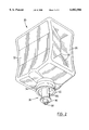
- FIG. 1 is a perspective view of a dispenser housing constructed in accordance with the present invention
- FIG. 2 is a perspective view of a liquid container and foam pump attached thereto;
- FIG. 3 is an exploded perspective view of the foam pump of FIG. 2;
- FIG. 4 is a cross sectional view taken along the line 4--4 of FIG. 3 when the foam pump is assembled and with the pump in the unactuated position;
- FIG. 5 is a view similar to FIG. 4 but showing the pump in the actuated position for expelling foam from the dispenser;
- FIG. 5b is a detailed view of the portion 5b of FIG. 5;
- FIG. 6 is a sectional view along the line 6--6 of FIG. 1;
- FIG. 7 is a sectional view similar to FIG. 6, but broken away and showing the pump in the depressed position.
- FIG. 8 is a perspective view, broken away, of a portion of the dispenser housing containing the foam pump.
- Dispenser 10 includes a housing 12 enclosing an upper liquid dispenser compartment 14 and a lower compartment 16 housing a foam producing pump to be discussed below.
- a hand actuated lever or pushbutton 18 is pivotally attached to lower compartment 16.
- An aperture 20 is located in the side of housing 12 for allowing access to a locking mechanism which locks the generally rectangular housing to a back plate (not shown) which is secured to a support surface such as a wall.
- a view port 28 is provided on the front of housing 12 for viewing the liquid level in the liquid container.
- Dispenser 10 is designed to releasibly receive therein a liquid container shown generally at 30 in FIG. 2 comprising a liquid storage compartment 32 and a liquid outlet or throat 34. Attached in the throat 34 of container 30 is a foam pump shown at 36.
- Container 30 is a flexible plastic container for holding liquids such as soap and the like and is collapsible. Container 30 is gusseted along the sides 38 thereof so that as liquid is drained the container collapses along creases 39 to form an I beam section.
- a view port 28 is provided on the front of housing 12, best seen in FIG. 1, for viewing the liquid level in liquid container 30 when the latter is assembled with the housing.
- FIG. 3 illustrates the components from which foam pump 36 is constructed and FIGS. 4 and 5 illustrate the assembled foamer in the two extreme positions.
- Foam pump 36 includes a cup-shaped enclosure member 40 having a top portion 42 with an aperture or fluid inlet 44 centrally located therein.
- Enclosure 40 includes a shoulder 46 against which the edge of throat 34 of container 30 (shown in ghost outline) abuts when pump 36 is assembled with container 30.
- Aperture 44 forms a fluid inlet for liquid entering pump 36 from compartment 32 to be discussed later.
- a cylindrical tube 48 (visible only in FIGS. 4 and 5) is attached to the top portion 42 on the interior of enclosure member 40 and encloses a passageway 50 in flow communication with bottle interior 32.
- Foam pump 36 is provided with an inlet valve 52 comprising a valve stem 54 and a valve head 56.
- Stem 54 is in the shape of a tuning fork with two spaced arms 58 depending from head 56 and defining a slot 60 therebetween.
- the end portions of arms 58 spaced from valve head 56 are provided with shoulders 62.
- Foam pump 36 includes a piston 66 provided with a cylindrical outer tube and a piston head 72 attached to one end of outer tube 68 and the other end of the shaft is provided with an O-ring 74 seated in an O-ring groove. Air vent inlet and outlet holes or apertures 76 are shown disposed about outer tube 68 spaced away from piston head 72. Piston head 72 is provided with an O-ring groove and an O-ring 78 is located in the groove extending circumferentially around piston head 72. Outer tube 68 is provided with cut-out sections 80 that extend from holes 76 down to piston head 72.
- Pump 36 includes a wire gauze, grid or mesh 84. Mesh 84 may be fabricated of plastic, wire or cloth material. Mesh 84 produces turbulence in the air-liquid mixture to aid in foam production.
- Piston 66 includes an inner cylindrical tube 69 which is concentric, and integrally formed with outer tube 68 at the upper ends of tubes 68 and 69 which face valve 52 into the interior compartment 32 of bottle 30.
- Inner tube 69 defines a passageway 70 through piston 66.
- Outer and inner tubes 68 and 69 respectively define an annular mixing chamber 77 between the tubes.
- a top hat valve 71 is fitted over the free end of inner tube 69 located in piston head 72 and valve 71 controls the flow of liquid from passageway 70 into mixing chamber 77.
- Top hat valve 71 is made of a flexible rubber or plastic having a desired elasticity so that it expands under pressure of the liquid to permit liquid to flow out around edge 73 as cylinder 86 is being pushed upwardly into cylinder 40.
- pump 36 further includes a second and opposing enclosure member which is slideably mounted within the first enclosure member and which includes a cylindrically shaped hollow cylinder 86 having an open end with a shoulder 88 spaced from the open upper end of the cylinder.
- Cylinder 86 includes a second cylindrically shaped member 90 with a larger diameter than cylinder 86 and concentric therewith and extending upwardly from shoulder 88.
- Cylindrical member 90 is provided with a chamfered upper end portion 92 which defines a circumferential slot 93.
- a flexible, cylindrical seal 94 includes a horizontal section 95 and a section 97 vertically upstanding from the inner edge of section 95 and a section 99 angled upwardly and outwardly from the outer edge of section 95. The vertically upstanding section 97 snaps into circumferential slot 93 when flexible seal 94 is assembled with cylinder 86.
- a circumferential rib 96 extends around the lower end of cylinder 86 and an outlet 98 is integrally formed with cylinder 86.
- Outlet 98 defines a passageway 101 that communicates with passageway 70 and includes a castellated web 106 which has an outer diameter sufficiently small to be received within piston head 72 and large enough to support mesh 84.
- mesh 84 is received within piston head 72 and piston 66 is inserted into cylinder 86 with mesh 84 supported on web 106.
- Top hat valve 71 is pushed part way onto the end portion of inner cylinder 69 with mesh 84 located between the end of valve 71 and web 106.
- the castellated portion of web 106 comprises slots 107 to permit exit of foam through outlet passageway 101, see FIGS. 4 and 5b.
- Cylinder 86 is received within cup-shaped cylindrical enclosure 40 and the outer diameter of flexible seal 94 is chosen to ensure a friction fit but which allows cylinder 86 to be telescoped with respect to cylindrical enclosure 40.
- the presence of flexible seal 94 is very advantageous because it provides a better seal which permits superior pressurizing of the air chamber than is achieved with similar structures absent the seal.
- Tube 68 is received within tube 48 and an O-ring 110 seated in O-ring groove 74 provides a seal between the outer surface of tube 68 and the inner wall of tube 48.
- Protective cap 100 (FIG. 3) is inserted into cup-shaped member 40 wherein the cylindrical section 102 is the same diameter as skirt 94 so that it is received within cup-shaped enclosure 40 and retained therein by a friction fit.
- cup-shaped enclosure 40 and the inner diameter of throat 34 of liquid container 30 are chosen so enclosure 40 can be inserted into the throat with a snug fit with the throat edge bearing against shoulder 46, see FIG. 4. Cup-shaped enclosure 40 is then welded to container 30 to permanently attach it thereto. Cylinder 86 and cup-shaped enclosure 40 when assembled define an air chamber 104 separate from both passageways 50 in tube 48 and passageway 70 through piston 66 and the interior of liquid storage compartment 32 of container 30. In this way the air used to mix with the liquid to form the foam is imported from the exterior of the container.
- the inner diameter of enclosure 40 and the outer diameter of flexible seal 94 are chosen to produce a substantially air-tight connection so that air chamber 104 can be pressurized by pushing piston 66 inwardly into tube 48 within enclosure 40.
- the upper O-ring 110 seals against liquid leaking into air chamber 104 while the lower O-ring 78 seals against air leaking out or back into air chamber 104.
- FIG. 6 illustrates a cross sectional view of housing 12 incorporating assembled container 30 and pump 36.
- lower compartment 16 of housing 12 is defined by side walls 120 and a front wall 122 having a generally rectangular aperture 124 located therein.
- Pushbutton 18 is pivotally connected to side walls 120 at position 126 and may be rotated about this pivotal connection. The ambit of this rotational movement is best seen by comparing the pushbutton positions in FIGS. 6 and 7 so that in the former, pushbutton 18 is fully extended and in FIG. 7 it is fully depressed.
- Dispenser housing 12 includes a locking mechanism for releasibly holding the collapsible bottle 30 and pump 36 in place.
- the locking mechanism comprises a pair of arms or levers 130 slidably movable in channels 132 formed in the interior of pushbutton 18 at the edges thereof. The other ends of arms 130 are received into slots 134 located in sleeves 136 which fit over the upper end of posts 138. Posts 138 pass through holes located in a yoke-shaped support bracket 140 rigidly attached to back wall 142 of the housing. Extending about the inner edge of the circular cut-out in bracket 140 is a slot 144.
- posts 138 opposed to the ends containing sleeves 136 are rigidly attached to a yoke shaped platform 146 containing a central cut-out 147 and an inwardly protruding shoulder 148.
- Each post 138 is provided with a spring 150 between bracket 140 and platform 146 to bias the platform down away from bracket 140.
- Platform 146 is provided with a pair of opposed bosses 160 each spring biased inwardly over shoulders 148 by springs 162. Bosses 160 travel in slots 164.
- a key (not shown) is inserted into aperture 20 (FIG. 1) to engage a locking mechanism 22 (FIG. 6) and when unlocked, hook 24 is disengaged from catch 26 and the front portion of the housing is pivoted downwardly away from back wall 120.
- container 30 and foam pump 36 are then inserted into housing 12 with cylinder 88 pushed up into section 40 and rib 46 is releasibly held in slot 144.
- Pushbutton 18 is then pushed inwards so that platform 146 is raised and when the convex inner surfaces of bosses 160 are engaged by rib 96 thereby pushing them outwardly against springs 162.
- inlet valve 52 In operation, to dispense foam from liquid from container 30 a user places the hand to receive foam under housing 12 adjacent to outlet 98 and with the other hand depresses pushbutton 18, see FIG. 6.
- inlet valve 52 is in the open position so that liquid flows into passageway 50 through slot 60 and aperture 44 in the direction of the arrows.
- the arrows in passageways 50 and 70 show the liquid flow path from chamber 32.
- the liquid soap fills passageway 50 in tube 48 and passageway 70 in piston 66.
- the liquid in passageways 50 and 70 Upon pressurizing the fluid chamber the liquid in passageways 50 and 70 is pressurized as cylinder 86 is pushed upwardly into enclosure 40 whereupon inlet valve 52 is pushed upwardly thereby closing off fluid inlet 44.
- the liquid in passageways 50 and 70 is further pressurized the liquid is forced out around the upper edge 73 of top hat valve 71 inserted on the end portion of tube 69 and into the mixing chamber 77.
- Air chamber 104 is being simultaneously pressurized as the volume is decreased so that air is forced (in the direction of the arrows shown) directly through holes 76 in tube 68 as shown in FIG. 4 when the holes 76 are not sealed within tube 48.
- the air enters the air chamber 77 between tubes 68 and 69 by being forced up the gap 80 between tubes 40 and 68 and through holes 76.
- the pressurized liquid soap forced out of passageway 70 is mixed with the pressurized air in mixing chamber 77 just above mesh 84 and the commingled mixture is forced through mesh 84 to produce foam.
- the properties of the foam, ratio of liquid to air may be controlled by the mesh or grid 84 and the relative volumes of the air chambers and fluid chambers.
- a foam with an air to liquid ratio of 20:1 has been found to be quite useful when liquid hand soap is being dispensed.
- Foam pump 36 is advantageous over prior art foamers because the same amount of pressure is required to operate the pump and produce the foam regardless of the amount of liquid in the container. Further, less work in general needs to be exerted since the liquid is not being forced up a tube or being forced through a thick porous plug. Also, the shape of the container is not restricted in shape by the need to hand squeeze it as with many of the prior art foamers. Another advantage of the foamer of the present invention is that the liquid is maintained in a relatively air-tight dispenser with no mixing with air until expelled from the fluid chamber. In this way long term oxidation of the ingredients making up the liquid is reduced. Every time a container is replaced, a new foam pump is provided with the container. This is advantageous since it avoids extended usage of the same pump so that problems such as blockage of passageways is avoided.
- a further advantage of the foaming device disclosed herein is that the need for thick, rigid porous plugs for generating foam as found in many of the prior art devices is avoided.
- the thin mesh or grid 84 as illustrated is sufficient to generate foam of appropriate quality.
- container 30 and foam pump 36 being fabricated of plastic, may be readily recycled after the contents of container 30 have been consumed.
- the combination of filled collapsible container 30 and foam pump 36 attached thereto (FIG. 2) is preferably sold as a single unit (with cap 100) as a replacement charge for use with dispenser housing 12 in applications requiring fixed locations for the dispenser such as rest rooms, other sanitary stations and the like.
- the combination of container 30 and foam pump 36 may be used in applications where the user carries the unit about and hand pumps foam from the device. This is possible because the combination of the air-tight connection of pump 36 with collapsible bottle 30 permits the foam to be dispensed with the bottle in any orientation while many of the prior art designs only function with the bottle in the upright position. This feature is very advantageous in for example hospitals where patients must be washed in bed.
- container 30 is held in one hand and cylinder 86 is pumped with the other hand to dispense foam.
- cylinder 86 may be interlocked with cup-shaped enclosure 40 by means of a boss and groove arrangement whereby a boss projects out from the side of cylinder 86 into a groove located on the interior surface of cup member 40. The groove would have two turns in it so that cylinder 86 could not be pulled out of enclosure 40 without rotation.
Abstract
Description
Claims (17)
Priority Applications (17)
| Application Number | Priority Date | Filing Date | Title |
|---|---|---|---|
| US09/050,130 US6082586A (en) | 1998-03-30 | 1998-03-30 | Liquid dispenser for dispensing foam |
| PL99337125A PL193402B1 (en) | 1998-03-30 | 1999-03-25 | Apparatus for dispensing a foamed liquid |
| EP99907809A EP0984715B2 (en) | 1998-03-30 | 1999-03-25 | Improved liquid dispenser for dispensing foam |
| PT99907809T PT984715E (en) | 1998-03-30 | 1999-03-25 | DISTRIBUTOR OF PERFORATED LIQUID FOR FOAM DISTRIBUTION |
| CA002296115A CA2296115C (en) | 1998-03-30 | 1999-03-25 | Improved liquid dispenser for dispensing foam |
| DK99907809.0T DK0984715T4 (en) | 1998-03-30 | 1999-03-25 | Improved liquid dispenser for foam release |
| PCT/IB1999/000526 WO1999049769A1 (en) | 1998-03-30 | 1999-03-25 | Improved liquid dispenser for dispensing foam |
| NZ501818A NZ501818A (en) | 1998-03-30 | 1999-03-25 | Improved liquid dispenser for dispensing foam |
| JP54910599A JP4294103B2 (en) | 1998-03-30 | 1999-03-25 | Improved foam dispensing liquid dispenser |
| AU27428/99A AU751305B2 (en) | 1998-03-30 | 1999-03-25 | Improved liquid dispenser for dispensing foam |
| ES99907809T ES2198129T5 (en) | 1998-03-30 | 1999-03-25 | IMPROVED LIQUID DISPENSER IN FOAM FORM. |
| BR9904917-1A BR9904917A (en) | 1998-03-30 | 1999-03-25 | Foam producing and dispensing device |
| AT99907809T ATE237982T1 (en) | 1998-03-30 | 1999-03-25 | LIQUID DISPENSER FOR PRODUCING FOAM |
| DE69907098T DE69907098T3 (en) | 1998-03-30 | 1999-03-25 | LIQUID DISPENSER FOR THE PRODUCTION OF FOAM |
| IS5255A IS2719B (en) | 1998-03-30 | 1999-11-19 | Improved dispenser for liquid to give foam |
| NO19995832A NO325659B1 (en) | 1998-03-30 | 1999-11-26 | Improved liquid dispenser for foam release |
| ZA9907512A ZA997512B (en) | 1998-03-30 | 1999-12-07 | Improved liquid dispenser for dispensing foam. |
Applications Claiming Priority (1)
| Application Number | Priority Date | Filing Date | Title |
|---|---|---|---|
| US09/050,130 US6082586A (en) | 1998-03-30 | 1998-03-30 | Liquid dispenser for dispensing foam |
Publications (1)
| Publication Number | Publication Date |
|---|---|
| US6082586A true US6082586A (en) | 2000-07-04 |
Family
ID=21963532
Family Applications (1)
| Application Number | Title | Priority Date | Filing Date |
|---|---|---|---|
| US09/050,130 Expired - Lifetime US6082586A (en) | 1998-03-30 | 1998-03-30 | Liquid dispenser for dispensing foam |
Country Status (17)
| Country | Link |
|---|---|
| US (1) | US6082586A (en) |
| EP (1) | EP0984715B2 (en) |
| JP (1) | JP4294103B2 (en) |
| AT (1) | ATE237982T1 (en) |
| AU (1) | AU751305B2 (en) |
| BR (1) | BR9904917A (en) |
| CA (1) | CA2296115C (en) |
| DE (1) | DE69907098T3 (en) |
| DK (1) | DK0984715T4 (en) |
| ES (1) | ES2198129T5 (en) |
| IS (1) | IS2719B (en) |
| NO (1) | NO325659B1 (en) |
| NZ (1) | NZ501818A (en) |
| PL (1) | PL193402B1 (en) |
| PT (1) | PT984715E (en) |
| WO (1) | WO1999049769A1 (en) |
| ZA (1) | ZA997512B (en) |
Cited By (140)
| Publication number | Priority date | Publication date | Assignee | Title |
|---|---|---|---|---|
| US6409050B1 (en) | 2001-03-20 | 2002-06-25 | Hygiene-Technik Inc. | Liquid dispenser for dispensing foam |
| US6547162B1 (en) * | 1998-04-17 | 2003-04-15 | Keltub B.V. | Foam spraying device |
| NL1019348C2 (en) * | 2001-11-12 | 2003-05-13 | Bentfield Europ Bv | Foam dispenser, housing and storage container therefor. |
| US6612468B2 (en) | 2000-09-15 | 2003-09-02 | Rieke Corporation | Dispenser pumps |
| US20040060945A1 (en) * | 2002-09-26 | 2004-04-01 | Miro Cater | Fluid dispenser with shuttling mixing chamber |
| NL1021710C2 (en) * | 2002-10-21 | 2004-04-22 | Airspray Nv | Foam pump dispenser, contains reservoir comprising dimensionally stable outer wall and flexible inner wall which become detached from each other as foam is dispensed |
| US20050006409A1 (en) * | 2001-11-12 | 2005-01-13 | Ganzeboom Wilhelmus Everhardus | Dispenser for dispensing a fluid, housing for such a dispenser, storage holder configured for placement therein and arrangement for the dosed pumping of a fluid from a fluid reservoir |
| US20050017025A1 (en) * | 2003-06-26 | 2005-01-27 | Gianandrea Niada | Dispenser for foamed detergents |
| US20050051579A1 (en) * | 2003-09-10 | 2005-03-10 | Kasting Thomas P. | Inverted dispensing pump |
| US20050072805A1 (en) * | 2003-08-20 | 2005-04-07 | Matthews Shaun Kerry | Foam dispenser with rigid container |
| US20050087563A1 (en) * | 2003-10-25 | 2005-04-28 | Ciavarella Nick E. | Universal collar |
| US20050109798A1 (en) * | 2003-09-10 | 2005-05-26 | Kasting Thomas P. | Inverted dispensing pump with vent baffle |
| US20050139612A1 (en) * | 2003-12-30 | 2005-06-30 | Matthews Shaun K. | Foam dispenser |
| US20050205600A1 (en) * | 2004-03-19 | 2005-09-22 | Heiner Ophardt | Dual component dispenser |
| US20050205608A1 (en) * | 2004-03-17 | 2005-09-22 | Heiner Ophardt | Self-orientating pump nozzle for fluid dispenser |
| US20050224519A1 (en) * | 2002-04-17 | 2005-10-13 | Law Brian R | Pump dispensers |
| US20050247737A1 (en) * | 2004-05-10 | 2005-11-10 | Chester Labs, Inc. | Hinged dispenser housing and adaptor |
| US20050258192A1 (en) * | 2004-05-07 | 2005-11-24 | Matthews Shaun K | Method of producing foamed cleaser with suspended particles therein and a dispenser therefore |
| US20050284888A1 (en) * | 2004-06-28 | 2005-12-29 | Rhodenbaugh Joseph W | Refillable product dispenser and system |
| US20060011655A1 (en) * | 2004-07-14 | 2006-01-19 | Heiner Ophardt | Sink side touchless foam dispenser |
| US7004356B1 (en) | 2003-07-28 | 2006-02-28 | Joseph S. Kanfer | Foam producing pump with anti-drip feature |
| WO2006029191A2 (en) * | 2004-09-07 | 2006-03-16 | Clayton Corporation | Anti-crossover dispensing applicator |
| US7086567B1 (en) * | 2002-07-25 | 2006-08-08 | Joseph S. Kanfer | Wall-mounted dispenser assembly with transparent window |
| US20060237483A1 (en) * | 2005-04-22 | 2006-10-26 | Heiner Ophardt | Bellows dispenser |
| US20060249538A1 (en) * | 2005-04-22 | 2006-11-09 | Heiner Ophardt | Foam pump with spring |
| US20060261091A1 (en) * | 2005-05-04 | 2006-11-23 | Bentfield Europe B.V. | Fluid product dispenser |
| US20060261083A1 (en) * | 2005-05-20 | 2006-11-23 | Heiner Ophardt | Foaming pump with improved air inlet valve |
| US20060273114A1 (en) * | 2005-04-22 | 2006-12-07 | Heiner Ophardt | Stepped pump foam dispenser |
| US20060283887A1 (en) * | 2005-01-14 | 2006-12-21 | Rowshan Jahan | Up-lock seal for dispenser pump |
| US20070241137A1 (en) * | 2006-04-14 | 2007-10-18 | Willis Daniel M | Foam soap generator |
| US20070251953A1 (en) * | 2006-04-28 | 2007-11-01 | Buckeye International, Inc. | Liquid and foamed soap dispensing |
| US20080051312A1 (en) * | 2006-08-23 | 2008-02-28 | David Lestage | Foamable compositions containing alcohol |
| WO2008049854A1 (en) | 2006-10-27 | 2008-05-02 | Stockhausen Gmbh | Foaming device for the production of personal-care or cleaning foam |
| US20090101671A1 (en) * | 2007-10-22 | 2009-04-23 | Georgia-Pacific Consumer Products Lp | Pumping dispenser |
| US20090188943A1 (en) * | 2008-01-30 | 2009-07-30 | Mccullough Anthony | Dispenser |
| US20090200339A1 (en) * | 2008-02-08 | 2009-08-13 | Quinlan Robert L | Bifurcated foam pump assembly |
| WO2009104994A1 (en) * | 2008-02-18 | 2009-08-27 | Sca Hygiene Products Ab | Disposable pump with suck-back mechanism |
| US20090236370A1 (en) * | 2008-03-18 | 2009-09-24 | Ray Eugene W | High velocity foam pump |
| US20090294478A1 (en) * | 2008-05-29 | 2009-12-03 | Gojo Industries, Inc. | Pull actuated foam pump |
| US20090314806A1 (en) * | 2008-06-20 | 2009-12-24 | Ray Eugene W | Two-stroke foam pump |
| WO2010025673A1 (en) * | 2008-09-03 | 2010-03-11 | Raymond Industrial Limited | Liquid foam dispensing device |
| US20100089951A1 (en) * | 2008-10-14 | 2010-04-15 | Yates James M | Dispensing tube assembly and foam generator for coaxial tubes |
| US20100111732A1 (en) * | 2008-11-03 | 2010-05-06 | Ciavarella Nick E | Piston pump with rotating pump actuator |
| US20100189809A1 (en) * | 2006-08-23 | 2010-07-29 | The Clorox Company | Foamable Compositions Containing Alcohol |
| US20110168740A1 (en) * | 2010-01-11 | 2011-07-14 | David John Pritchett | Inverted dispenser pump with liquid inlet cup valve |
| US8020734B1 (en) * | 2008-03-21 | 2011-09-20 | Vandendries Robert H | Hand washing timing system |
| WO2011133085A1 (en) | 2010-04-22 | 2011-10-27 | Sca Hygiene Products Ab | Dispenser and liquid container |
| US8056768B2 (en) | 2007-12-28 | 2011-11-15 | Snodgrass David L | Foam pump assembly |
| US20110278323A1 (en) * | 2009-02-03 | 2011-11-17 | Sivel | Self-Cleaning Tip |
| USD667526S1 (en) | 2010-02-10 | 2012-09-18 | Larry Covington | Bait station |
| US8308027B2 (en) | 2009-12-01 | 2012-11-13 | Regent Medical Center | Automatic soap dispenser with top-side motor and methods |
| US20120308405A1 (en) * | 2011-06-06 | 2012-12-06 | Gojo Industries, Inc. | Modular pump |
| US8336740B1 (en) | 2005-11-02 | 2012-12-25 | Daansen Warren S | Fluid dispenser and pump adapter system therefor |
| US8365963B2 (en) | 2008-01-30 | 2013-02-05 | Evonik Stockhausen, Llc | Fluid dispenser selectively secured to a countertop |
| US20130037573A1 (en) * | 2011-08-11 | 2013-02-14 | Gojo Industries, Inc. | Split body pumps for foam dispensers and refill units |
| US8499981B2 (en) | 2008-02-08 | 2013-08-06 | Gojo Industries, Inc. | Bifurcated stem foam pump |
| WO2013126644A1 (en) * | 2012-02-22 | 2013-08-29 | Nader Gary | Apparatus to assure the washing of hands |
| US8528795B2 (en) | 2008-09-01 | 2013-09-10 | Rieke Corporation | Liquid dosing devices |
| US8556130B2 (en) | 2010-01-14 | 2013-10-15 | Rieke Corporation | Pump dispensers |
| US20130284763A1 (en) * | 2012-04-27 | 2013-10-31 | Pibed Limited | Foam dispenser |
| US20130333551A1 (en) * | 2012-06-19 | 2013-12-19 | Gotohti.Com Inc. | Telescopic bell piston for pump |
| US20130341356A1 (en) * | 2012-06-26 | 2013-12-26 | Gojo Industries, Inc. | Grit and foam dispenser |
| US8651328B2 (en) | 2011-07-14 | 2014-02-18 | Georgia-Pacific Consumer Products Lp | Pumping dispenser shield |
| US20140097205A1 (en) * | 2012-10-04 | 2014-04-10 | Arminak & Associates, Llc | Mixing chamber for two fluid constituents |
| CN101503133B (en) * | 2008-02-08 | 2014-04-23 | 高爽工业公司 | Bifurcated stem foam pump |
| US8720107B1 (en) * | 2006-04-11 | 2014-05-13 | Vm Products Inc. | Tamper-resistant fly control station and methods for using the same |
| US20140158715A1 (en) * | 2012-12-11 | 2014-06-12 | Gojo Industries, Inc. | Vented check valves, pumps and refill units with vented check valves |
| US20140203045A1 (en) * | 2013-01-23 | 2014-07-24 | Christopher J. Mann | Shield for a fluid dispenser |
| US20140203047A1 (en) * | 2013-01-23 | 2014-07-24 | Gojo Industries, Inc. | Pumps with container vents |
| US20140209638A1 (en) * | 2013-01-25 | 2014-07-31 | Gojo Industries, Inc. | Sequenced adjustable volume pumps, refill units and dispensers |
| US8820585B1 (en) | 2013-03-15 | 2014-09-02 | Pibed Limited | Foam dispenser with a porous foaming element |
| US8827119B2 (en) * | 2013-01-23 | 2014-09-09 | Gojo Industries, Inc. | Pull pumps, refill units and dispensers for pull pumps |
| US8851331B2 (en) | 2012-05-04 | 2014-10-07 | Ecolab Usa Inc. | Fluid dispensers with adjustable dosing |
| US8875952B2 (en) | 2012-03-12 | 2014-11-04 | Gojo Industries, Inc. | Air-activated sequenced valve split foam pump |
| US20140367419A1 (en) * | 2013-06-14 | 2014-12-18 | Gojo Industries, Inc. | Foam cartridges, pumps, refill units and foam dispensers utilizing the same |
| US8939323B2 (en) | 2010-07-01 | 2015-01-27 | Rieke Corporation | Dispensers |
| US8963721B2 (en) | 2010-03-23 | 2015-02-24 | Harkap Partners, LLC | Hand hygiene compliance device |
| US8991655B2 (en) | 2013-02-15 | 2015-03-31 | Ecolab Usa Inc. | Fluid dispensers with increased mechanical advantage |
| US20150157176A1 (en) * | 2013-01-17 | 2015-06-11 | Dispensing Dynamics International | Dispenser apparatus for dispensing liquid soap, lotion or other liquid |
| US20150291345A1 (en) * | 2014-04-11 | 2015-10-15 | Op-Hygiene Ip Gmbh | Pump Maintaining Container Internal Pressure |
| USD742137S1 (en) | 2013-03-15 | 2015-11-03 | Buckeye International, Inc. | Dispenser for dispensing cleaning solutions |
| US20150313423A1 (en) * | 2012-08-23 | 2015-11-05 | Gojo Industries, Inc. | Horizontal pumps, refill units and foam dispensers with integral air compressors |
| US20150342421A1 (en) * | 2014-05-28 | 2015-12-03 | Gojo Industries, Inc. | Dual air chamber foam pumps, refill units and dispensers |
| US9211559B2 (en) | 2010-07-01 | 2015-12-15 | Rieke Corporation | Dispensers |
| US20160025541A1 (en) * | 2014-07-25 | 2016-01-28 | Mezurware, Llc | Dispensing devices for dispensing precise doses of liquid |
| US9307871B2 (en) | 2012-08-30 | 2016-04-12 | Gojo Industries, Inc. | Horizontal pumps, refill units and foam dispensers |
| US9340337B2 (en) | 2012-05-01 | 2016-05-17 | Ecolab Usa Inc. | Dispenser with lockable pushbutton |
| US9433960B2 (en) | 2008-09-01 | 2016-09-06 | Rieke Corporation | Liquid dosing devices |
| US20160333874A1 (en) * | 2015-05-12 | 2016-11-17 | Gregory L. Indruk | Foam pump and dispenser employing same |
| USD773849S1 (en) | 2015-03-13 | 2016-12-13 | Buckeye International, Inc. | Dispenser for dispensing a cleaning solution |
| US20170020347A1 (en) * | 2015-04-07 | 2017-01-26 | Vi-Jon, Inc. | Dispenser assembly |
| US20170020348A1 (en) * | 2015-07-23 | 2017-01-26 | William J. Schalitz | Disposable Soap Dispenser |
| US9596963B2 (en) | 2014-07-30 | 2017-03-21 | Gojo Industries, Inc. | Vented refill units and dispensers having vented refill units |
| US9611839B2 (en) | 2012-05-09 | 2017-04-04 | Gojo Industries, Inc. | Low residual inverted pumps, dispensers and refill units |
| USD784726S1 (en) | 2014-12-23 | 2017-04-25 | Buckeye International, Inc. | Dispenser for dispensing cleaning solutions |
| WO2017077269A1 (en) * | 2015-11-02 | 2017-05-11 | Deb Ip Limited | Foaming component |
| WO2017078520A1 (en) | 2015-11-04 | 2017-05-11 | Gab Engineering & Development B.V. | Storage holder for a dispenser |
| US9648992B2 (en) | 2013-12-19 | 2017-05-16 | Gojo Industries, Inc. | Pumps with vents to vent inverted containers and refill units having non-collapsing containers |
| WO2017087930A1 (en) * | 2015-11-20 | 2017-05-26 | Gojo Industries, Inc. | Foam dispensing systems, pumps and refill units having high air to liquid ratios |
| US20170172357A1 (en) * | 2015-12-17 | 2017-06-22 | Peter Bai | Foam generator |
| US9700181B1 (en) | 2016-08-31 | 2017-07-11 | Vi-Jon, Inc. | Dispenser assembly including enclosure with handle |
| US9718069B2 (en) | 2014-05-12 | 2017-08-01 | Deb Ip Limited | Foam pump |
| US9718070B2 (en) | 2012-08-31 | 2017-08-01 | Arminak & Associates, Llc | Inverted squeeze foamer |
| US9737177B2 (en) | 2014-05-20 | 2017-08-22 | Gojo Industries, Inc. | Two-part fluid delivery systems |
| USD795608S1 (en) | 2015-10-12 | 2017-08-29 | Buckeye International, Inc. | Dispenser for dispensing cleaning solutions, a cover piece for a dispenser for dispensing cleaning solutions, and a portion of a dispenser for dispensing cleaning solutions |
| WO2017183974A1 (en) | 2016-04-20 | 2017-10-26 | Gab Engineering & Development B.V. | Storage holder for a dispenser |
| US9943196B2 (en) | 2015-11-12 | 2018-04-17 | Gojo Industries, Inc. | Sequentially activated multi-diaphragm foam pumps, refill units and dispenser systems |
| US10034583B2 (en) | 2016-03-04 | 2018-07-31 | Gpcp Ip Holdings Llc | Dispenser with stroke adjustment capabilities |
| US10065199B2 (en) | 2015-11-13 | 2018-09-04 | Gojo Industries, Inc. | Foaming cartridge |
| US10080468B2 (en) | 2015-12-04 | 2018-09-25 | Gojo Industries, Inc. | Sequentially activated multi-diaphragm foam pumps, refill units and dispenser systems |
| US10080467B2 (en) | 2015-11-20 | 2018-09-25 | Gojo Industries, Inc. | Foam dispensing systems, pumps and refill units having high air to liquid ratios |
| US10080466B2 (en) | 2015-11-18 | 2018-09-25 | Gojo Industries, Inc. | Sequentially activated multi-diaphragm foam pumps, refill units and dispenser systems |
| US10143339B2 (en) | 2016-04-06 | 2018-12-04 | Gojo Industries, Inc. | Sequentially activated multi-diaphragm foam pumps, refill units and dispenser systems |
| US10160590B2 (en) | 2014-02-24 | 2018-12-25 | Gojo Industries, Inc. | Vented non-collapsing containers, dispensers and refill units having vented non-collapsing containers |
| US10189614B2 (en) | 2013-03-15 | 2019-01-29 | Bissell Homecare, Inc. | Container and cap assembly |
| US10278549B1 (en) * | 2016-10-31 | 2019-05-07 | Gpcp Ip Holdings Llc | Counter-mounted skincare product dispenser |
| CN110312504A (en) * | 2017-02-23 | 2019-10-08 | 德比Ip有限公司 | Expandable cleaning compositions |
| US10441115B2 (en) | 2016-02-11 | 2019-10-15 | Gojo Industries, Inc. | High quality non-aerosol hand sanitizing foam |
| US20200085669A1 (en) * | 2015-10-13 | 2020-03-19 | Apollo Industrial Co., Ltd. | Foam generator for inverted compression receptacles |
| US10676340B2 (en) | 2015-08-27 | 2020-06-09 | Deb Ip Limited | Filling hose |
| US10823161B2 (en) * | 2015-05-12 | 2020-11-03 | Gregory L. Indruk | Foam pump and dispenser employing same |
| US10843214B2 (en) * | 2018-11-29 | 2020-11-24 | Op-Hygiene Ip Gmbh | Valve retention under pressure |
| US10912426B2 (en) | 2016-04-06 | 2021-02-09 | Gojo Industries, Inc. | Sequentially activated multi-diaphragm foam pumps, refill units and dispenser systems |
| EP3875010A1 (en) * | 2020-03-02 | 2021-09-08 | Hans Georg Hagleitner | Dispenser |
| US11219907B1 (en) * | 2017-12-29 | 2022-01-11 | He-Products Llc | Foam producing and dispensing apparatus and method |
| US11229502B1 (en) | 2017-06-03 | 2022-01-25 | Knight, Llc | Instrument cleaning systems and methods |
| US11247220B2 (en) * | 2017-12-15 | 2022-02-15 | Kao Corporation | Foam discharger |
| US20220055051A1 (en) * | 2018-12-03 | 2022-02-24 | Coty Inc. | Fluid dispenser |
| US11371493B2 (en) * | 2013-10-03 | 2022-06-28 | Zobele Holding S.P.A. | Device for dispensing a substance comprising a chamber defining a substance inlet, a substance outlet, an air inlet, and an air outlet, a piston located inside the chamber and whose movement causes the exit of both the substance and air to outside of the device |
| US11596274B2 (en) * | 2016-09-29 | 2023-03-07 | Kao Corporation | Foam discharge container |
| US11634314B1 (en) | 2022-11-17 | 2023-04-25 | Sharkninja Operating Llc | Dosing accuracy |
| US11647860B1 (en) | 2022-05-13 | 2023-05-16 | Sharkninja Operating Llc | Flavored beverage carbonation system |
| US20230166277A1 (en) * | 2020-04-27 | 2023-06-01 | Kao Corporation | Foam discharge container |
| RU219167U1 (en) * | 2023-04-10 | 2023-06-30 | Евгений Александрович Непокульчицкий | LIQUID DOSING DEVICE |
| US11738988B1 (en) | 2022-11-17 | 2023-08-29 | Sharkninja Operating Llc | Ingredient container valve control |
| US11745996B1 (en) | 2022-11-17 | 2023-09-05 | Sharkninja Operating Llc | Ingredient containers for use with beverage dispensers |
| US11751585B1 (en) | 2022-05-13 | 2023-09-12 | Sharkninja Operating Llc | Flavored beverage carbonation system |
| US11871867B1 (en) | 2023-03-22 | 2024-01-16 | Sharkninja Operating Llc | Additive container with bottom cover |
| US11925287B1 (en) | 2023-03-22 | 2024-03-12 | Sharkninja Operating Llc | Additive container with inlet tube |
| US11931704B1 (en) | 2023-06-16 | 2024-03-19 | Sharkninja Operating Llc | Carbonation chamber |
Families Citing this family (24)
| Publication number | Priority date | Publication date | Assignee | Title |
|---|---|---|---|---|
| EP1147818A1 (en) * | 2000-04-20 | 2001-10-24 | Supermatic Kunststoff Ag | Device for producing and discharging foam |
| US6910579B2 (en) | 2002-05-28 | 2005-06-28 | Georgia-Pacific Corporation | Refillable flexible sheet dispenser |
| NL1030992C2 (en) | 2006-01-24 | 2007-07-26 | Airspray Nv | Squeeze foamer. |
| GB2437510A (en) * | 2006-04-26 | 2007-10-31 | Packaging Innovation Ltd | Dispenser mechanism |
| US8302820B2 (en) | 2007-09-21 | 2012-11-06 | Packaging Innovation Ltd | Dispenser mechanism |
| AU2014208298B2 (en) * | 2008-02-08 | 2016-01-07 | Gojo Industries Inc. | Bifurcated foam pump assembly |
| AU2014253540B2 (en) * | 2008-02-08 | 2016-01-07 | Gojo Industries Inc. | Bifurcated stem foam pump |
| US8047403B2 (en) * | 2008-02-08 | 2011-11-01 | Gojo Industries, Inc. | Bifurcated stem foam pump |
| US8104650B2 (en) * | 2008-06-06 | 2012-01-31 | Pibed Ltd. | Anti drip device for liquid dispensers |
| US8276784B2 (en) | 2008-12-11 | 2012-10-02 | Gojo Industries, Inc. | Pressure activated automatic source switching dispenser system |
| GB0912065D0 (en) * | 2009-07-10 | 2009-08-19 | Reckitt & Colman Overseas | A fluid delivery system |
| GB2472235B (en) | 2009-07-29 | 2011-07-06 | Brightwell Dispensers Ltd | Dispensing device with a disposable pump |
| AT508916B1 (en) * | 2009-11-06 | 2011-05-15 | Hagleitner Hans Georg | DISPENSER FOR DELIVERING PORTIONS OF A FLUID |
| CN103118797B (en) | 2010-06-15 | 2016-04-27 | 布莱特维尔分配器有限公司 | Foam pump |
| RU2502536C1 (en) * | 2012-12-28 | 2013-12-27 | Олег Савельевич Кочетов | Foam generator |
| WO2015161018A1 (en) * | 2014-04-16 | 2015-10-22 | Gojo Industries, Inc. | Foam dispensing pump with compressible air inlet chamber for providing residual suck-back |
| CN108136422B (en) | 2015-09-25 | 2021-10-29 | 易希提卫生与保健公司 | Pump for dispensing fluids |
| RU2702403C1 (en) | 2015-09-25 | 2019-10-08 | Эссити Хайджин Энд Хелт Актиеболаг | Pump with polymer spring |
| GB201600894D0 (en) * | 2016-01-18 | 2016-03-02 | Obrist Closures Switzerland | Dispensing closure |
| PL3600687T3 (en) | 2017-03-29 | 2023-04-11 | Essity Hygiene And Health Aktiebolag | Plastomer spring with captive valve |
| EP3773100B1 (en) | 2018-03-28 | 2023-09-20 | Gojo Industries, Inc. | Foam pumps, refill units and dispensers with differential bore suck-back mechanism |
| US10898034B1 (en) | 2019-07-02 | 2021-01-26 | Armin Arminak | All plastic hand foam pump |
| WO2022053158A1 (en) * | 2020-09-14 | 2022-03-17 | Kao Corporation | Foam dispenser |
| US11744413B2 (en) | 2021-10-07 | 2023-09-05 | Deb Ip Limited | Dispenser assembly |
Citations (23)
| Publication number | Priority date | Publication date | Assignee | Title |
|---|---|---|---|---|
| US3422993A (en) * | 1967-07-26 | 1969-01-21 | Johnson & Son Inc S C | Foam dispensing device and package |
| US3709437A (en) * | 1968-09-23 | 1973-01-09 | Hershel Earl Wright | Method and device for producing foam |
| US3743146A (en) * | 1970-01-21 | 1973-07-03 | Zyma Sa | Dosing valve |
| US3985271A (en) * | 1975-06-06 | 1976-10-12 | Glasrock Products, Inc. | Foam generating and dispensing device |
| US4019657A (en) * | 1975-03-03 | 1977-04-26 | Spitzer Joseph G | Aerosol containers for foaming and delivering aerosols |
| US4022351A (en) * | 1975-04-03 | 1977-05-10 | Hershel Earl Wright | Foam dispenser |
| US4238056A (en) * | 1978-03-06 | 1980-12-09 | Towlsaver, Inc. | Soap dispenser having a pivotable dispensing lever and a rotatable flow valve |
| US4621749A (en) * | 1984-02-21 | 1986-11-11 | Go-Jo Industries | Dispensing apparatus |
| GB2193904A (en) * | 1986-07-28 | 1988-02-24 | Ballard Med Prod | Foam-producer dispenser |
| EP0392238A1 (en) * | 1989-04-08 | 1990-10-17 | Ing. Erich Pfeiffer GmbH & Co. KG | Dispensing facility for media |
| US4978036A (en) * | 1988-11-15 | 1990-12-18 | Koller Enterprises, Inc. | Dispensing valve |
| US5048750A (en) * | 1988-04-05 | 1991-09-17 | Supermatic Kunststoff Ag | Device for producing and dispensing foam |
| US5156307A (en) * | 1990-03-24 | 1992-10-20 | Callahan George E | Dispenser for foaming of a filled liquid material |
| US5165577A (en) * | 1991-05-20 | 1992-11-24 | Heiner Ophardt | Disposable plastic liquid pump |
| US5174476A (en) * | 1991-05-06 | 1992-12-29 | Steiner Company, Inc. | Liquid soap dispensing system |
| US5248066A (en) * | 1992-03-27 | 1993-09-28 | Ecolab Inc. | Liquid dispenser with collapsible reservoir holder |
| EP0565713A1 (en) * | 1990-11-07 | 1993-10-20 | Daiwa Can Company, Limited | Bubble spouting pump vessel |
| US5289952A (en) * | 1991-04-30 | 1994-03-01 | L'oreal | Device for dispensing foam, and push-button for a device of this kind |
| EP0618147A2 (en) * | 1993-02-26 | 1994-10-05 | Bespak plc | Air purge pump dispenser |
| US5372281A (en) * | 1992-10-19 | 1994-12-13 | Ballard Medical Products | Disposable tray sump foamer, assembly and methods |
| US5425404A (en) * | 1993-04-20 | 1995-06-20 | Minnesota Mining And Manufacturing Company | Gravity feed fluid dispensing system |
| US5445288A (en) * | 1994-04-05 | 1995-08-29 | Sprintvest Corporation Nv | Liquid dispenser for dispensing foam |
| DE4429454A1 (en) * | 1994-08-19 | 1996-02-22 | Katz Otto | Spray pump using air=atomised fluids |
Family Cites Families (7)
| Publication number | Priority date | Publication date | Assignee | Title |
|---|---|---|---|---|
| GB712353A (en) † | 1952-03-13 | 1954-07-21 | Wild A G & Co Ltd | Improvements in or relating to manually-operated reciprocating pumps |
| US4477000A (en) † | 1979-05-10 | 1984-10-16 | Europtool Trust | Apparatus for forming portions of soap foam |
| DE3262348D1 (en) † | 1981-11-18 | 1985-03-28 | Cws Ag | Device for the portional formation of soap lather |
| JPH0669161U (en) † | 1993-03-05 | 1994-09-27 | 大和製罐株式会社 | Pump type foam container |
| DE9407178U1 (en) † | 1994-05-02 | 1994-07-07 | Reidel Hermann | Device for producing and dispensing foam |
| CH688021A5 (en) † | 1994-07-18 | 1997-04-30 | Cws Ag | Apparatus for formation of soap scum and its use. |
| US5556005A (en) † | 1995-01-09 | 1996-09-17 | Sprintvest Corporation Nv | Collapsible soap dispenser |
-
1998
- 1998-03-30 US US09/050,130 patent/US6082586A/en not_active Expired - Lifetime
-
1999
- 1999-03-25 WO PCT/IB1999/000526 patent/WO1999049769A1/en active IP Right Grant
- 1999-03-25 AU AU27428/99A patent/AU751305B2/en not_active Expired
- 1999-03-25 EP EP99907809A patent/EP0984715B2/en not_active Expired - Lifetime
- 1999-03-25 PT PT99907809T patent/PT984715E/en unknown
- 1999-03-25 JP JP54910599A patent/JP4294103B2/en not_active Expired - Lifetime
- 1999-03-25 PL PL99337125A patent/PL193402B1/en unknown
- 1999-03-25 NZ NZ501818A patent/NZ501818A/en not_active IP Right Cessation
- 1999-03-25 DK DK99907809.0T patent/DK0984715T4/en active
- 1999-03-25 CA CA002296115A patent/CA2296115C/en not_active Expired - Lifetime
- 1999-03-25 DE DE69907098T patent/DE69907098T3/en not_active Expired - Lifetime
- 1999-03-25 AT AT99907809T patent/ATE237982T1/en active
- 1999-03-25 ES ES99907809T patent/ES2198129T5/en not_active Expired - Lifetime
- 1999-03-25 BR BR9904917-1A patent/BR9904917A/en not_active IP Right Cessation
- 1999-11-19 IS IS5255A patent/IS2719B/en unknown
- 1999-11-26 NO NO19995832A patent/NO325659B1/en not_active IP Right Cessation
- 1999-12-07 ZA ZA9907512A patent/ZA997512B/en unknown
Patent Citations (23)
| Publication number | Priority date | Publication date | Assignee | Title |
|---|---|---|---|---|
| US3422993A (en) * | 1967-07-26 | 1969-01-21 | Johnson & Son Inc S C | Foam dispensing device and package |
| US3709437A (en) * | 1968-09-23 | 1973-01-09 | Hershel Earl Wright | Method and device for producing foam |
| US3743146A (en) * | 1970-01-21 | 1973-07-03 | Zyma Sa | Dosing valve |
| US4019657A (en) * | 1975-03-03 | 1977-04-26 | Spitzer Joseph G | Aerosol containers for foaming and delivering aerosols |
| US4022351A (en) * | 1975-04-03 | 1977-05-10 | Hershel Earl Wright | Foam dispenser |
| US3985271A (en) * | 1975-06-06 | 1976-10-12 | Glasrock Products, Inc. | Foam generating and dispensing device |
| US4238056A (en) * | 1978-03-06 | 1980-12-09 | Towlsaver, Inc. | Soap dispenser having a pivotable dispensing lever and a rotatable flow valve |
| US4621749A (en) * | 1984-02-21 | 1986-11-11 | Go-Jo Industries | Dispensing apparatus |
| GB2193904A (en) * | 1986-07-28 | 1988-02-24 | Ballard Med Prod | Foam-producer dispenser |
| US5048750A (en) * | 1988-04-05 | 1991-09-17 | Supermatic Kunststoff Ag | Device for producing and dispensing foam |
| US4978036A (en) * | 1988-11-15 | 1990-12-18 | Koller Enterprises, Inc. | Dispensing valve |
| EP0392238A1 (en) * | 1989-04-08 | 1990-10-17 | Ing. Erich Pfeiffer GmbH & Co. KG | Dispensing facility for media |
| US5156307A (en) * | 1990-03-24 | 1992-10-20 | Callahan George E | Dispenser for foaming of a filled liquid material |
| EP0565713A1 (en) * | 1990-11-07 | 1993-10-20 | Daiwa Can Company, Limited | Bubble spouting pump vessel |
| US5289952A (en) * | 1991-04-30 | 1994-03-01 | L'oreal | Device for dispensing foam, and push-button for a device of this kind |
| US5174476A (en) * | 1991-05-06 | 1992-12-29 | Steiner Company, Inc. | Liquid soap dispensing system |
| US5165577A (en) * | 1991-05-20 | 1992-11-24 | Heiner Ophardt | Disposable plastic liquid pump |
| US5248066A (en) * | 1992-03-27 | 1993-09-28 | Ecolab Inc. | Liquid dispenser with collapsible reservoir holder |
| US5372281A (en) * | 1992-10-19 | 1994-12-13 | Ballard Medical Products | Disposable tray sump foamer, assembly and methods |
| EP0618147A2 (en) * | 1993-02-26 | 1994-10-05 | Bespak plc | Air purge pump dispenser |
| US5425404A (en) * | 1993-04-20 | 1995-06-20 | Minnesota Mining And Manufacturing Company | Gravity feed fluid dispensing system |
| US5445288A (en) * | 1994-04-05 | 1995-08-29 | Sprintvest Corporation Nv | Liquid dispenser for dispensing foam |
| DE4429454A1 (en) * | 1994-08-19 | 1996-02-22 | Katz Otto | Spray pump using air=atomised fluids |
Cited By (263)
| Publication number | Priority date | Publication date | Assignee | Title |
|---|---|---|---|---|
| US6547162B1 (en) * | 1998-04-17 | 2003-04-15 | Keltub B.V. | Foam spraying device |
| US6612468B2 (en) | 2000-09-15 | 2003-09-02 | Rieke Corporation | Dispenser pumps |
| GB2380470B (en) * | 2001-03-20 | 2005-03-09 | Hygiene Technik Inc | Liquid dispenser for dispensing foam |
| GB2380470A (en) * | 2001-03-20 | 2003-04-09 | Hygiene Technik Inc | Liquid dispenser for dispensing foam |
| USRE40319E1 (en) | 2001-03-20 | 2008-05-20 | Hygiene-Technik Inc. | Liquid dispenser for dispensing foam |
| US6409050B1 (en) | 2001-03-20 | 2002-06-25 | Hygiene-Technik Inc. | Liquid dispenser for dispensing foam |
| US6601736B2 (en) | 2001-03-20 | 2003-08-05 | Hygiene-Technik Inc. | Liquid dispenser for dispensing foam |
| US20050006409A1 (en) * | 2001-11-12 | 2005-01-13 | Ganzeboom Wilhelmus Everhardus | Dispenser for dispensing a fluid, housing for such a dispenser, storage holder configured for placement therein and arrangement for the dosed pumping of a fluid from a fluid reservoir |
| US7611033B2 (en) * | 2001-11-12 | 2009-11-03 | Technical Concepts Bentfield B.V. | Foam dispenser, housing and storage holder therefor |
| US20050006408A1 (en) * | 2001-11-12 | 2005-01-13 | Ganzeboom Wilhelmus Everhardus | Foam dispenser, housing and storage holder therefor |
| AU2002343848B2 (en) * | 2001-11-12 | 2005-09-15 | Technical Concepts Bentfield B.V. | Dispenser for dispensing a fluid, housing for such a dispenser, storage holder destined for placement therein and arrangement for the dosed pumping of a fluid from a fluid reservoir |
| US7198177B2 (en) | 2001-11-12 | 2007-04-03 | Bentfield Europe B.V. | Dispenser for dispensing a fluid, housing for such a dispenser, storage holder configured for placement therein and arrangement for the dosed pumping of a fluid from a fluid reservoir |
| AU2002343237B2 (en) * | 2001-11-12 | 2006-03-02 | Technical Concepts Bentfield B.V. | Foam dispenser, housing and storage holder therefor |
| NL1019348C2 (en) * | 2001-11-12 | 2003-05-13 | Bentfield Europ Bv | Foam dispenser, housing and storage container therefor. |
| WO2003059524A1 (en) * | 2001-11-12 | 2003-07-24 | Bentfield Europe B.V. | Foam dispenser, housing and storage holder therefor |
| US7461762B2 (en) | 2002-04-17 | 2008-12-09 | Rieke Corporation | Pump dispensers |
| US20070215643A1 (en) * | 2002-04-17 | 2007-09-20 | Rieke Corporation | Pump dispensers |
| US20050224519A1 (en) * | 2002-04-17 | 2005-10-13 | Law Brian R | Pump dispensers |
| US7641077B2 (en) | 2002-04-17 | 2010-01-05 | Rieke Corporation | Pump dispensers |
| US7938297B2 (en) | 2002-04-17 | 2011-05-10 | Rieke Corporation | Pump dispensers |
| CN100391619C (en) * | 2002-04-17 | 2008-06-04 | 雷克公司 | Pump dispensers |
| US7086567B1 (en) * | 2002-07-25 | 2006-08-08 | Joseph S. Kanfer | Wall-mounted dispenser assembly with transparent window |
| US20040060945A1 (en) * | 2002-09-26 | 2004-04-01 | Miro Cater | Fluid dispenser with shuttling mixing chamber |
| US6868990B2 (en) | 2002-09-26 | 2005-03-22 | Emsar, Inc. | Fluid dispenser with shuttling mixing chamber |
| NL1021710C2 (en) * | 2002-10-21 | 2004-04-22 | Airspray Nv | Foam pump dispenser, contains reservoir comprising dimensionally stable outer wall and flexible inner wall which become detached from each other as foam is dispensed |
| US7063239B2 (en) * | 2003-06-26 | 2006-06-20 | Qts S.R.L. | Dispenser for foamed detergents |
| US20050017025A1 (en) * | 2003-06-26 | 2005-01-27 | Gianandrea Niada | Dispenser for foamed detergents |
| US7004356B1 (en) | 2003-07-28 | 2006-02-28 | Joseph S. Kanfer | Foam producing pump with anti-drip feature |
| US20050072805A1 (en) * | 2003-08-20 | 2005-04-07 | Matthews Shaun Kerry | Foam dispenser with rigid container |
| US7389893B2 (en) | 2003-09-10 | 2008-06-24 | Rieke Corporation | Inverted dispensing pump |
| US20050109798A1 (en) * | 2003-09-10 | 2005-05-26 | Kasting Thomas P. | Inverted dispensing pump with vent baffle |
| US7325704B2 (en) | 2003-09-10 | 2008-02-05 | Rieke Corporation | Inverted dispensing pump with vent baffle |
| US20050051579A1 (en) * | 2003-09-10 | 2005-03-10 | Kasting Thomas P. | Inverted dispensing pump |
| US7950548B2 (en) * | 2003-10-25 | 2011-05-31 | Gojo Industries, Inc. | Universal collar |
| US20050087563A1 (en) * | 2003-10-25 | 2005-04-28 | Ciavarella Nick E. | Universal collar |
| US20050139612A1 (en) * | 2003-12-30 | 2005-06-30 | Matthews Shaun K. | Foam dispenser |
| US20050205608A1 (en) * | 2004-03-17 | 2005-09-22 | Heiner Ophardt | Self-orientating pump nozzle for fluid dispenser |
| US7225948B2 (en) * | 2004-03-17 | 2007-06-05 | Hygiene-Technik Inc. | Self-orientating pump nozzle for fluid dispenser |
| DE102005012121B4 (en) * | 2004-03-19 | 2015-08-20 | Hygiene-Technik Inc. | Two-component dispenser |
| US20100102089A1 (en) * | 2004-03-19 | 2010-04-29 | Heiner Ophardt | Dual component dispenser |
| US20050205600A1 (en) * | 2004-03-19 | 2005-09-22 | Heiner Ophardt | Dual component dispenser |
| US7823751B2 (en) | 2004-03-19 | 2010-11-02 | Hygiene-Technik Inc. | Dual component dispenser |
| US7661561B2 (en) | 2004-03-19 | 2010-02-16 | Hygiene-Technik Inc. | Dual component dispenser |
| FR2867700A1 (en) | 2004-03-19 | 2005-09-23 | Hygiene Technik Inc | DISTRIBUTOR FOR TWO COMPONENTS |
| US20050258192A1 (en) * | 2004-05-07 | 2005-11-24 | Matthews Shaun K | Method of producing foamed cleaser with suspended particles therein and a dispenser therefore |
| US10736824B2 (en) | 2004-05-07 | 2020-08-11 | Deb Ip Limited | Foamed cleanser with suspended particles |
| US8002151B2 (en) * | 2004-05-07 | 2011-08-23 | Deb Ip Limited | Method of producing foamed cleanser with suspended particles therein and a dispenser therefore |
| US7278554B2 (en) | 2004-05-10 | 2007-10-09 | Chester Labs, Inc. | Hinged dispenser housing and adaptor |
| US20050247737A1 (en) * | 2004-05-10 | 2005-11-10 | Chester Labs, Inc. | Hinged dispenser housing and adaptor |
| US7654417B2 (en) | 2004-06-28 | 2010-02-02 | Aluta, Inc. | Refillable product dispenser and system |
| US20050284888A1 (en) * | 2004-06-28 | 2005-12-29 | Rhodenbaugh Joseph W | Refillable product dispenser and system |
| US7364053B2 (en) | 2004-07-14 | 2008-04-29 | Hygiene-Technik Inc. | Sink side touchless foam dispenser |
| US20080121660A1 (en) * | 2004-07-14 | 2008-05-29 | Heiner Ophardt | Sink side touchless foam dispenser nozzle assembly |
| US20060011655A1 (en) * | 2004-07-14 | 2006-01-19 | Heiner Ophardt | Sink side touchless foam dispenser |
| US7455197B2 (en) | 2004-07-14 | 2008-11-25 | Gotohti.Com Inc. | Sink side touchless foam dispenser nozzle assembly |
| WO2006029191A2 (en) * | 2004-09-07 | 2006-03-16 | Clayton Corporation | Anti-crossover dispensing applicator |
| WO2006029191A3 (en) * | 2004-09-07 | 2009-04-09 | Clayton Corp | Anti-crossover dispensing applicator |
| US7802701B2 (en) | 2005-01-14 | 2010-09-28 | Rieke Corporation | Up-lock seal for dispenser pump |
| US20060283887A1 (en) * | 2005-01-14 | 2006-12-21 | Rowshan Jahan | Up-lock seal for dispenser pump |
| US7303099B2 (en) | 2005-04-22 | 2007-12-04 | Gotohti.Com Inc. | Stepped pump foam dispenser |
| US7770874B2 (en) | 2005-04-22 | 2010-08-10 | Gotohii.com Inc. | Foam pump with spring |
| US8474664B2 (en) | 2005-04-22 | 2013-07-02 | Gotohti.Com Inc. | Foam pump with bellows spring |
| US20060273114A1 (en) * | 2005-04-22 | 2006-12-07 | Heiner Ophardt | Stepped pump foam dispenser |
| US20060237483A1 (en) * | 2005-04-22 | 2006-10-26 | Heiner Ophardt | Bellows dispenser |
| US20060249538A1 (en) * | 2005-04-22 | 2006-11-09 | Heiner Ophardt | Foam pump with spring |
| US7708166B2 (en) | 2005-04-22 | 2010-05-04 | Gotohti.Com | Bellows dispenser |
| US20100260632A1 (en) * | 2005-04-22 | 2010-10-14 | Heiner Ophardt | Foam pump with bellows spring |
| US20060261091A1 (en) * | 2005-05-04 | 2006-11-23 | Bentfield Europe B.V. | Fluid product dispenser |
| US7337930B2 (en) | 2005-05-20 | 2008-03-04 | Gotohti.Com Inc. | Foaming pump with improved air inlet valve |
| US20060261083A1 (en) * | 2005-05-20 | 2006-11-23 | Heiner Ophardt | Foaming pump with improved air inlet valve |
| US8336740B1 (en) | 2005-11-02 | 2012-12-25 | Daansen Warren S | Fluid dispenser and pump adapter system therefor |
| US8720107B1 (en) * | 2006-04-11 | 2014-05-13 | Vm Products Inc. | Tamper-resistant fly control station and methods for using the same |
| US9504361B2 (en) * | 2006-04-14 | 2016-11-29 | Gojo Industries, Inc. | Foam soap generator |
| US7819289B2 (en) | 2006-04-14 | 2010-10-26 | Joseph S Kanfer | Foam soap generator |
| US20110006086A1 (en) * | 2006-04-14 | 2011-01-13 | Yates James M | Foam soap generator |
| AU2010249197B2 (en) * | 2006-04-14 | 2012-08-16 | Kanfer, Joseph S. | Foam soap generator |
| US20070241137A1 (en) * | 2006-04-14 | 2007-10-18 | Willis Daniel M | Foam soap generator |
| US8863989B2 (en) | 2006-04-28 | 2014-10-21 | Buckeye International, Inc. | Soap dispenser including actuator with spring arm |
| US8505776B2 (en) | 2006-04-28 | 2013-08-13 | Scott Criswell | Liquid and foamed soap dispensing |
| US7780039B2 (en) | 2006-04-28 | 2010-08-24 | Buckeye International, Inc. | Soap dispensing pump head with vacuum applying drip guard member |
| US20100270329A1 (en) * | 2006-04-28 | 2010-10-28 | Buckeye International, Inc. | Liquid and foamed soap dispensing |
| US20070251953A1 (en) * | 2006-04-28 | 2007-11-01 | Buckeye International, Inc. | Liquid and foamed soap dispensing |
| US20100187263A1 (en) * | 2006-08-23 | 2010-07-29 | The Clorox Company | Foamable Composition Containing Alcohol |
| US20100189809A1 (en) * | 2006-08-23 | 2010-07-29 | The Clorox Company | Foamable Compositions Containing Alcohol |
| US8354364B2 (en) | 2006-08-23 | 2013-01-15 | The Clorox Company | Foamable composition containing alcohol |
| US7723279B2 (en) | 2006-08-23 | 2010-05-25 | The Clorox Company | Foamable compositions containing alcohol |
| US7790663B2 (en) | 2006-08-23 | 2010-09-07 | The Clorox Company | Foamable composition containing alcohol |
| US20080051312A1 (en) * | 2006-08-23 | 2008-02-28 | David Lestage | Foamable compositions containing alcohol |
| WO2008049854A1 (en) | 2006-10-27 | 2008-05-02 | Stockhausen Gmbh | Foaming device for the production of personal-care or cleaning foam |
| US20090101671A1 (en) * | 2007-10-22 | 2009-04-23 | Georgia-Pacific Consumer Products Lp | Pumping dispenser |
| US8746510B2 (en) | 2007-10-22 | 2014-06-10 | Georgia-Pacific Consumer Products Lp | Pumping dispenser |
| US8261950B2 (en) | 2007-10-22 | 2012-09-11 | Georgia-Pacific Consumer Products Lp | Pumping dispenser |
| US8056768B2 (en) | 2007-12-28 | 2011-11-15 | Snodgrass David L | Foam pump assembly |
| US8020731B2 (en) | 2008-01-30 | 2011-09-20 | Evonik Stockhausen, Llc | Dispenser |
| US8365963B2 (en) | 2008-01-30 | 2013-02-05 | Evonik Stockhausen, Llc | Fluid dispenser selectively secured to a countertop |
| US20090188943A1 (en) * | 2008-01-30 | 2009-07-30 | Mccullough Anthony | Dispenser |
| US20090200339A1 (en) * | 2008-02-08 | 2009-08-13 | Quinlan Robert L | Bifurcated foam pump assembly |
| US8763863B2 (en) * | 2008-02-08 | 2014-07-01 | Gojo Industries, Inc. | Bifurcated foam pump, dispensers and refill units |
| US8313010B2 (en) | 2008-02-08 | 2012-11-20 | Gojo Industries, Inc. | Bifurcated foam pump assembly |
| US8499981B2 (en) | 2008-02-08 | 2013-08-06 | Gojo Industries, Inc. | Bifurcated stem foam pump |
| CN101503133B (en) * | 2008-02-08 | 2014-04-23 | 高爽工业公司 | Bifurcated stem foam pump |
| WO2009104994A1 (en) * | 2008-02-18 | 2009-08-27 | Sca Hygiene Products Ab | Disposable pump with suck-back mechanism |
| US20100327019A1 (en) * | 2008-02-18 | 2010-12-30 | Sca Hygiene Products Ab | Disposable pump with suck-back mechanism |
| US8708200B2 (en) | 2008-02-18 | 2014-04-29 | Sca Hygiene Products Ab | Disposable pump with suck-back mechanism |
| US20110155767A1 (en) * | 2008-03-18 | 2011-06-30 | Gojo Industries, Inc. | High velocity foam pump |
| US20090236370A1 (en) * | 2008-03-18 | 2009-09-24 | Ray Eugene W | High velocity foam pump |
| US7861895B2 (en) * | 2008-03-18 | 2011-01-04 | Gojo Industries, Inc. | High velocity foam pump |
| US8261948B2 (en) * | 2008-03-18 | 2012-09-11 | Gojo Industries, Inc. | High velocity foam pump |
| US8499982B2 (en) * | 2008-03-18 | 2013-08-06 | Gojo Industries, Inc. | High velocity foam pump |
| US8020734B1 (en) * | 2008-03-21 | 2011-09-20 | Vandendries Robert H | Hand washing timing system |
| US8313008B2 (en) | 2008-05-29 | 2012-11-20 | Gojo Industries, Inc. | Pull actuated foam pump |
| US20090294478A1 (en) * | 2008-05-29 | 2009-12-03 | Gojo Industries, Inc. | Pull actuated foam pump |
| US9072412B2 (en) * | 2008-05-29 | 2015-07-07 | Gojo Industries, Inc. | Pull actuated foam pump |
| US20120160879A1 (en) * | 2008-05-29 | 2012-06-28 | Gojo Industries, Inc. | Pull actuated foam pump |
| CN101606829B (en) * | 2008-06-20 | 2014-12-24 | 高爽工业公司 | Two-stroke foam pump |
| US8267284B2 (en) * | 2008-06-20 | 2012-09-18 | Gojo Industries, Inc. | Two-stroke foam pump |
| US20090314806A1 (en) * | 2008-06-20 | 2009-12-24 | Ray Eugene W | Two-stroke foam pump |
| US8528795B2 (en) | 2008-09-01 | 2013-09-10 | Rieke Corporation | Liquid dosing devices |
| US20160355304A1 (en) * | 2008-09-01 | 2016-12-08 | Rieke Corporation | Liquid dosing devices |
| US9433960B2 (en) | 2008-09-01 | 2016-09-06 | Rieke Corporation | Liquid dosing devices |
| WO2010025673A1 (en) * | 2008-09-03 | 2010-03-11 | Raymond Industrial Limited | Liquid foam dispensing device |
| TWI488693B (en) * | 2008-10-14 | 2015-06-21 | Gojo Ind Inc | Dispensing tube assembly and foam generator for coaxial tubes |
| US20100089951A1 (en) * | 2008-10-14 | 2010-04-15 | Yates James M | Dispensing tube assembly and foam generator for coaxial tubes |
| US8286836B2 (en) * | 2008-10-14 | 2012-10-16 | Gojo Industries, Inc. | Dispensing tube assembly and foam generator for coaxial tubes |
| US8235689B2 (en) * | 2008-11-03 | 2012-08-07 | Gojo Industries, Inc. | Piston pump with rotating pump actuator |
| US20100111732A1 (en) * | 2008-11-03 | 2010-05-06 | Ciavarella Nick E | Piston pump with rotating pump actuator |
| US8714408B2 (en) * | 2009-02-03 | 2014-05-06 | Sivel | Self-cleaning tip |
| US20110278323A1 (en) * | 2009-02-03 | 2011-11-17 | Sivel | Self-Cleaning Tip |
| US8308027B2 (en) | 2009-12-01 | 2012-11-13 | Regent Medical Center | Automatic soap dispenser with top-side motor and methods |
| US8418889B2 (en) | 2010-01-11 | 2013-04-16 | Rieke Corporation | Inverted dispenser pump with liquid inlet cup valve |
| US20110168740A1 (en) * | 2010-01-11 | 2011-07-14 | David John Pritchett | Inverted dispenser pump with liquid inlet cup valve |
| US8556130B2 (en) | 2010-01-14 | 2013-10-15 | Rieke Corporation | Pump dispensers |
| USD667526S1 (en) | 2010-02-10 | 2012-09-18 | Larry Covington | Bait station |
| US8963721B2 (en) | 2010-03-23 | 2015-02-24 | Harkap Partners, LLC | Hand hygiene compliance device |
| US20130105519A1 (en) * | 2010-04-22 | 2013-05-02 | Robin Sundberg | Dispenser and liquid container |
| WO2011133085A1 (en) | 2010-04-22 | 2011-10-27 | Sca Hygiene Products Ab | Dispenser and liquid container |
| AU2011243257B2 (en) * | 2010-04-22 | 2016-06-02 | Essity Hygiene And Health Aktiebolag | Dispenser and liquid container |
| CN102858215B (en) * | 2010-04-22 | 2016-10-12 | Sca卫生用品公司 | Allotter and liquid container |
| CN102858215A (en) * | 2010-04-22 | 2013-01-02 | Sca卫生用品公司 | Dispenser and liquid container |
| WO2011133077A1 (en) * | 2010-04-22 | 2011-10-27 | Sca Hygiene Products Ab | Pump soap dispenser |
| US8807398B2 (en) * | 2010-04-22 | 2014-08-19 | Sca Hygiene Products Ab | Dispenser and liquid container |
| RU2504323C1 (en) * | 2010-04-22 | 2014-01-20 | Ска Хайджин Продактс Аб | Dispensing device and container for liquid |
| US9211559B2 (en) | 2010-07-01 | 2015-12-15 | Rieke Corporation | Dispensers |
| US9010584B2 (en) | 2010-07-01 | 2015-04-21 | Rieke Corporation | Dispensers |
| US9346068B2 (en) | 2010-07-01 | 2016-05-24 | Rieke Corporation | Dispensers |
| US8939323B2 (en) | 2010-07-01 | 2015-01-27 | Rieke Corporation | Dispensers |
| US9101952B2 (en) * | 2011-06-06 | 2015-08-11 | Gojo Industries, Inc. | Modular pump |
| US20120308405A1 (en) * | 2011-06-06 | 2012-12-06 | Gojo Industries, Inc. | Modular pump |
| US8651328B2 (en) | 2011-07-14 | 2014-02-18 | Georgia-Pacific Consumer Products Lp | Pumping dispenser shield |
| US8662355B2 (en) * | 2011-08-11 | 2014-03-04 | Gojo Industries, Inc. | Split body pumps for foam dispensers and refill units |
| US20130037573A1 (en) * | 2011-08-11 | 2013-02-14 | Gojo Industries, Inc. | Split body pumps for foam dispensers and refill units |
| WO2013126644A1 (en) * | 2012-02-22 | 2013-08-29 | Nader Gary | Apparatus to assure the washing of hands |
| US9433328B2 (en) | 2012-03-12 | 2016-09-06 | Gojo Insustries, Inc. | Air-activated sequenced valve split foam pump |
| US8875952B2 (en) | 2012-03-12 | 2014-11-04 | Gojo Industries, Inc. | Air-activated sequenced valve split foam pump |
| US20130284763A1 (en) * | 2012-04-27 | 2013-10-31 | Pibed Limited | Foam dispenser |
| US8814005B2 (en) * | 2012-04-27 | 2014-08-26 | Pibed Limited | Foam dispenser |
| WO2013160071A1 (en) | 2012-04-27 | 2013-10-31 | Pibed Limited | A foam dispenser |
| US9340337B2 (en) | 2012-05-01 | 2016-05-17 | Ecolab Usa Inc. | Dispenser with lockable pushbutton |
| US8851331B2 (en) | 2012-05-04 | 2014-10-07 | Ecolab Usa Inc. | Fluid dispensers with adjustable dosing |
| US9611839B2 (en) | 2012-05-09 | 2017-04-04 | Gojo Industries, Inc. | Low residual inverted pumps, dispensers and refill units |
| US9587655B2 (en) * | 2012-06-19 | 2017-03-07 | Gotohti.Com Inc. | Telescopic bell piston for pump |
| US20130333551A1 (en) * | 2012-06-19 | 2013-12-19 | Gotohti.Com Inc. | Telescopic bell piston for pump |
| US9066636B2 (en) * | 2012-06-26 | 2015-06-30 | Gojo Industries, Inc. | Grit and foam dispenser |
| US20130341356A1 (en) * | 2012-06-26 | 2013-12-26 | Gojo Industries, Inc. | Grit and foam dispenser |
| US20150313423A1 (en) * | 2012-08-23 | 2015-11-05 | Gojo Industries, Inc. | Horizontal pumps, refill units and foam dispensers with integral air compressors |
| US9854947B2 (en) * | 2012-08-23 | 2018-01-02 | Gojo Industries, Inc. | Horizontal pumps, refill units and foam dispensers with integral air compressors |
| US9307871B2 (en) | 2012-08-30 | 2016-04-12 | Gojo Industries, Inc. | Horizontal pumps, refill units and foam dispensers |
| US9718070B2 (en) | 2012-08-31 | 2017-08-01 | Arminak & Associates, Llc | Inverted squeeze foamer |
| US20140097205A1 (en) * | 2012-10-04 | 2014-04-10 | Arminak & Associates, Llc | Mixing chamber for two fluid constituents |
| US9586217B2 (en) * | 2012-10-04 | 2017-03-07 | Arminak & Associates, Llc | Mixing chamber for two fluid constituents |
| US9266134B2 (en) * | 2012-12-11 | 2016-02-23 | Gojo Industries, Inc. | Vented check valves, pumps and refill units with vented check valves |
| US20140158715A1 (en) * | 2012-12-11 | 2014-06-12 | Gojo Industries, Inc. | Vented check valves, pumps and refill units with vented check valves |
| US20150157176A1 (en) * | 2013-01-17 | 2015-06-11 | Dispensing Dynamics International | Dispenser apparatus for dispensing liquid soap, lotion or other liquid |
| US9655478B2 (en) * | 2013-01-17 | 2017-05-23 | Dispensing Dynamics International | Dispenser apparatus for dispensing liquid soap, lotion or other liquid |
| US9027797B2 (en) * | 2013-01-23 | 2015-05-12 | Gojo Industries, Inc. | Shield for a fluid dispenser |
| US20140203047A1 (en) * | 2013-01-23 | 2014-07-24 | Gojo Industries, Inc. | Pumps with container vents |
| US20140203045A1 (en) * | 2013-01-23 | 2014-07-24 | Christopher J. Mann | Shield for a fluid dispenser |
| US9038862B2 (en) * | 2013-01-23 | 2015-05-26 | Gojo Industries, Inc. | Pumps with container vents |
| US9204767B2 (en) | 2013-01-23 | 2015-12-08 | Gojo Industries, Inc. | Pull pumps, refill units and dispensers for pull pumps |
| US8827119B2 (en) * | 2013-01-23 | 2014-09-09 | Gojo Industries, Inc. | Pull pumps, refill units and dispensers for pull pumps |
| US20140209638A1 (en) * | 2013-01-25 | 2014-07-31 | Gojo Industries, Inc. | Sequenced adjustable volume pumps, refill units and dispensers |
| US9254068B2 (en) * | 2013-01-25 | 2016-02-09 | Gojo Industries, Inc. | Sequenced adjustable volume pumps, refill units and dispensers |
| US9408502B2 (en) | 2013-02-15 | 2016-08-09 | Ecolab Usa Inc. | Fluid dispensers with increased mechanical advantage |
| US8991655B2 (en) | 2013-02-15 | 2015-03-31 | Ecolab Usa Inc. | Fluid dispensers with increased mechanical advantage |
| USD742137S1 (en) | 2013-03-15 | 2015-11-03 | Buckeye International, Inc. | Dispenser for dispensing cleaning solutions |
| US10894639B2 (en) | 2013-03-15 | 2021-01-19 | Bissell Inc. | Container and cap assembly |
| US10189614B2 (en) | 2013-03-15 | 2019-01-29 | Bissell Homecare, Inc. | Container and cap assembly |
| US10647481B2 (en) | 2013-03-15 | 2020-05-12 | Bissell Inc. | Container and cap assembly |
| US8820585B1 (en) | 2013-03-15 | 2014-09-02 | Pibed Limited | Foam dispenser with a porous foaming element |
| US20140367419A1 (en) * | 2013-06-14 | 2014-12-18 | Gojo Industries, Inc. | Foam cartridges, pumps, refill units and foam dispensers utilizing the same |
| US11371493B2 (en) * | 2013-10-03 | 2022-06-28 | Zobele Holding S.P.A. | Device for dispensing a substance comprising a chamber defining a substance inlet, a substance outlet, an air inlet, and an air outlet, a piston located inside the chamber and whose movement causes the exit of both the substance and air to outside of the device |
| US9648992B2 (en) | 2013-12-19 | 2017-05-16 | Gojo Industries, Inc. | Pumps with vents to vent inverted containers and refill units having non-collapsing containers |
| US10160590B2 (en) | 2014-02-24 | 2018-12-25 | Gojo Industries, Inc. | Vented non-collapsing containers, dispensers and refill units having vented non-collapsing containers |
| US20150291345A1 (en) * | 2014-04-11 | 2015-10-15 | Op-Hygiene Ip Gmbh | Pump Maintaining Container Internal Pressure |
| US9731890B2 (en) * | 2014-04-11 | 2017-08-15 | Op-Hygiene Ip Gmbh | Pump maintaining container internal pressure |
| US9718069B2 (en) | 2014-05-12 | 2017-08-01 | Deb Ip Limited | Foam pump |
| US9737177B2 (en) | 2014-05-20 | 2017-08-22 | Gojo Industries, Inc. | Two-part fluid delivery systems |
| US9642502B2 (en) * | 2014-05-28 | 2017-05-09 | Gojo Industries, Inc. | Dual air chamber foam pumps, refill units and dispensers |
| US20150342421A1 (en) * | 2014-05-28 | 2015-12-03 | Gojo Industries, Inc. | Dual air chamber foam pumps, refill units and dispensers |
| US20160025541A1 (en) * | 2014-07-25 | 2016-01-28 | Mezurware, Llc | Dispensing devices for dispensing precise doses of liquid |
| US9574921B2 (en) * | 2014-07-25 | 2017-02-21 | Mezurware Llc | Dispensing devices for dispensing precise doses of liquid |
| US9936840B2 (en) | 2014-07-30 | 2018-04-10 | Gojo Industries, Inc. | Vented refill units and dispensers having vented refill units |
| US9596963B2 (en) | 2014-07-30 | 2017-03-21 | Gojo Industries, Inc. | Vented refill units and dispensers having vented refill units |
| USD784726S1 (en) | 2014-12-23 | 2017-04-25 | Buckeye International, Inc. | Dispenser for dispensing cleaning solutions |
| USD773849S1 (en) | 2015-03-13 | 2016-12-13 | Buckeye International, Inc. | Dispenser for dispensing a cleaning solution |
| US10376106B2 (en) * | 2015-04-07 | 2019-08-13 | Vi-Jon, Inc. | Dispenser assembly |
| US20170020347A1 (en) * | 2015-04-07 | 2017-01-26 | Vi-Jon, Inc. | Dispenser assembly |
| US10022023B2 (en) * | 2015-04-07 | 2018-07-17 | Vi-Jon, Inc. | Dispenser assembly |
| US10823161B2 (en) * | 2015-05-12 | 2020-11-03 | Gregory L. Indruk | Foam pump and dispenser employing same |
| US20160333874A1 (en) * | 2015-05-12 | 2016-11-17 | Gregory L. Indruk | Foam pump and dispenser employing same |
| US11236737B2 (en) * | 2015-05-12 | 2022-02-01 | Gregory L. Indruk | Foam pump and dispenser employing same |
| US10359031B2 (en) * | 2015-05-12 | 2019-07-23 | Gregory L. Indruk | Foam pump and dispenser employing same |
| US10682020B2 (en) * | 2015-07-23 | 2020-06-16 | William J. Schalitz | Disposable soap dispenser |
| US11076725B2 (en) | 2015-07-23 | 2021-08-03 | William J. Schalitz | Disposable soap dispenser |
| US10321790B2 (en) * | 2015-07-23 | 2019-06-18 | Spartan Chemical Company, Inc. | Disposable soap dispenser |
| US20170020348A1 (en) * | 2015-07-23 | 2017-01-26 | William J. Schalitz | Disposable Soap Dispenser |
| US10932627B2 (en) | 2015-08-27 | 2021-03-02 | Deb Ip Limited | Filling hose |
| US10676340B2 (en) | 2015-08-27 | 2020-06-09 | Deb Ip Limited | Filling hose |
| USD795608S1 (en) | 2015-10-12 | 2017-08-29 | Buckeye International, Inc. | Dispenser for dispensing cleaning solutions, a cover piece for a dispenser for dispensing cleaning solutions, and a portion of a dispenser for dispensing cleaning solutions |
| US20200085669A1 (en) * | 2015-10-13 | 2020-03-19 | Apollo Industrial Co., Ltd. | Foam generator for inverted compression receptacles |
| US10765590B2 (en) * | 2015-10-13 | 2020-09-08 | Apollo Industrial Co., Ltd. | Foam generator for inverted compression receptacles |
| US11013375B2 (en) | 2015-11-02 | 2021-05-25 | Deb Ip Limited | Wipes with foam |
| CN108348112A (en) * | 2015-11-02 | 2018-07-31 | 戴博Ip有限公司 | Foamed assembly |
| WO2017077269A1 (en) * | 2015-11-02 | 2017-05-11 | Deb Ip Limited | Foaming component |
| WO2017078520A1 (en) | 2015-11-04 | 2017-05-11 | Gab Engineering & Development B.V. | Storage holder for a dispenser |
| US9943196B2 (en) | 2015-11-12 | 2018-04-17 | Gojo Industries, Inc. | Sequentially activated multi-diaphragm foam pumps, refill units and dispenser systems |
| US10065199B2 (en) | 2015-11-13 | 2018-09-04 | Gojo Industries, Inc. | Foaming cartridge |
| US10080466B2 (en) | 2015-11-18 | 2018-09-25 | Gojo Industries, Inc. | Sequentially activated multi-diaphragm foam pumps, refill units and dispenser systems |
| US10080467B2 (en) | 2015-11-20 | 2018-09-25 | Gojo Industries, Inc. | Foam dispensing systems, pumps and refill units having high air to liquid ratios |
| WO2017087930A1 (en) * | 2015-11-20 | 2017-05-26 | Gojo Industries, Inc. | Foam dispensing systems, pumps and refill units having high air to liquid ratios |
| US10080468B2 (en) | 2015-12-04 | 2018-09-25 | Gojo Industries, Inc. | Sequentially activated multi-diaphragm foam pumps, refill units and dispenser systems |
| US9750377B2 (en) * | 2015-12-17 | 2017-09-05 | Peter Bai | Foam generator |
| US20170172357A1 (en) * | 2015-12-17 | 2017-06-22 | Peter Bai | Foam generator |
| US10441115B2 (en) | 2016-02-11 | 2019-10-15 | Gojo Industries, Inc. | High quality non-aerosol hand sanitizing foam |
| US11000161B2 (en) | 2016-02-11 | 2021-05-11 | Gojo Industries, Inc. | High quality non-aerosol hand sanitizing foam |
| US10034583B2 (en) | 2016-03-04 | 2018-07-31 | Gpcp Ip Holdings Llc | Dispenser with stroke adjustment capabilities |
| US11596273B2 (en) | 2016-04-06 | 2023-03-07 | Gojo Industries, Inc. | Sequentially activated multi-diaphragm foam pumps, refill units and dispenser systems |
| US10143339B2 (en) | 2016-04-06 | 2018-12-04 | Gojo Industries, Inc. | Sequentially activated multi-diaphragm foam pumps, refill units and dispenser systems |
| US10912426B2 (en) | 2016-04-06 | 2021-02-09 | Gojo Industries, Inc. | Sequentially activated multi-diaphragm foam pumps, refill units and dispenser systems |
| WO2017183974A1 (en) | 2016-04-20 | 2017-10-26 | Gab Engineering & Development B.V. | Storage holder for a dispenser |
| US9700181B1 (en) | 2016-08-31 | 2017-07-11 | Vi-Jon, Inc. | Dispenser assembly including enclosure with handle |
| US11596274B2 (en) * | 2016-09-29 | 2023-03-07 | Kao Corporation | Foam discharge container |
| US10278549B1 (en) * | 2016-10-31 | 2019-05-07 | Gpcp Ip Holdings Llc | Counter-mounted skincare product dispenser |
| CN115590788B (en) * | 2017-02-23 | 2024-03-01 | 德比Ip有限公司 | Foamable cleaning compositions |
| CN110312504A (en) * | 2017-02-23 | 2019-10-08 | 德比Ip有限公司 | Expandable cleaning compositions |
| CN115590788A (en) * | 2017-02-23 | 2023-01-13 | 德比Ip有限公司(Gb) | Foamable cleaning compositions |
| US11229502B1 (en) | 2017-06-03 | 2022-01-25 | Knight, Llc | Instrument cleaning systems and methods |
| US11247220B2 (en) * | 2017-12-15 | 2022-02-15 | Kao Corporation | Foam discharger |
| US11219907B1 (en) * | 2017-12-29 | 2022-01-11 | He-Products Llc | Foam producing and dispensing apparatus and method |
| US10843214B2 (en) * | 2018-11-29 | 2020-11-24 | Op-Hygiene Ip Gmbh | Valve retention under pressure |
| US20220055051A1 (en) * | 2018-12-03 | 2022-02-24 | Coty Inc. | Fluid dispenser |
| US11628458B2 (en) * | 2018-12-03 | 2023-04-18 | Wella International Operations Switzerland Sàrl | Fluid dispenser |
| EP3875010A1 (en) * | 2020-03-02 | 2021-09-08 | Hans Georg Hagleitner | Dispenser |
| US20230166277A1 (en) * | 2020-04-27 | 2023-06-01 | Kao Corporation | Foam discharge container |
| US11647860B1 (en) | 2022-05-13 | 2023-05-16 | Sharkninja Operating Llc | Flavored beverage carbonation system |
| US11751585B1 (en) | 2022-05-13 | 2023-09-12 | Sharkninja Operating Llc | Flavored beverage carbonation system |
| US11738988B1 (en) | 2022-11-17 | 2023-08-29 | Sharkninja Operating Llc | Ingredient container valve control |
| US11745996B1 (en) | 2022-11-17 | 2023-09-05 | Sharkninja Operating Llc | Ingredient containers for use with beverage dispensers |
| US11634314B1 (en) | 2022-11-17 | 2023-04-25 | Sharkninja Operating Llc | Dosing accuracy |
| US11871867B1 (en) | 2023-03-22 | 2024-01-16 | Sharkninja Operating Llc | Additive container with bottom cover |
| US11925287B1 (en) | 2023-03-22 | 2024-03-12 | Sharkninja Operating Llc | Additive container with inlet tube |
| RU219167U1 (en) * | 2023-04-10 | 2023-06-30 | Евгений Александрович Непокульчицкий | LIQUID DOSING DEVICE |
| US11931704B1 (en) | 2023-06-16 | 2024-03-19 | Sharkninja Operating Llc | Carbonation chamber |
Also Published As
| Publication number | Publication date |
|---|---|
| NO325659B1 (en) | 2008-06-30 |
| EP0984715B1 (en) | 2003-04-23 |
| IS5255A (en) | 1999-11-19 |
| DK0984715T3 (en) | 2003-08-18 |
| ATE237982T1 (en) | 2003-05-15 |
| PL337125A1 (en) | 2000-07-31 |
| AU751305B2 (en) | 2002-08-15 |
| EP0984715A1 (en) | 2000-03-15 |
| JP2002501423A (en) | 2002-01-15 |
| IS2719B (en) | 2011-02-15 |
| ES2198129T3 (en) | 2004-01-16 |
| WO1999049769A1 (en) | 1999-10-07 |
| PT984715E (en) | 2003-08-29 |
| ES2198129T5 (en) | 2010-07-26 |
| BR9904917A (en) | 2000-06-20 |
| CA2296115C (en) | 2005-12-27 |
| DE69907098D1 (en) | 2003-05-28 |
| AU2742899A (en) | 1999-10-18 |
| PL193402B1 (en) | 2007-02-28 |
| EP0984715B2 (en) | 2010-01-13 |
| NO995832L (en) | 1999-11-26 |
| JP4294103B2 (en) | 2009-07-08 |
| DE69907098T3 (en) | 2010-08-12 |
| NO995832D0 (en) | 1999-11-26 |
| DE69907098T2 (en) | 2003-10-30 |
| ZA997512B (en) | 2000-10-12 |
| CA2296115A1 (en) | 1999-10-07 |
| DK0984715T4 (en) | 2010-05-17 |
| NZ501818A (en) | 2002-04-26 |
Similar Documents
| Publication | Publication Date | Title |
|---|---|---|
| US6082586A (en) | Liquid dispenser for dispensing foam | |
| EP0703831B1 (en) | Liquid dispenser for dispensing foam | |
| TWI457104B (en) | Bifurcated stem foam pump | |
| US9072412B2 (en) | Pull actuated foam pump | |
| EP2067426B1 (en) | Angled slot foam dispenser | |
| US8662355B2 (en) | Split body pumps for foam dispensers and refill units | |
| EP2209558B1 (en) | Device for dispensing fluid | |
| GB2024049A (en) | A foam-generating device | |
| TW201345472A (en) | Vortex atomizing foam pump and refill unit utilizing same | |
| WO2009142886A1 (en) | Foam dispenser with compressible porous mixing element | |
| US20030056406A1 (en) | Iron comprising a pump for water/textile additive mixture | |
| MXPA99011027A (en) | Improved liquid dispenser for dispensing foam |
Legal Events
| Date | Code | Title | Description |
|---|---|---|---|
| AS | Assignment |
Owner name: SPRINTVEST CORPORATION N.V., NETHERLANDS Free format text: ASSIGNMENT OF ASSIGNORS INTEREST;ASSIGNOR:BANKS, STEWART;REEL/FRAME:009587/0931 Effective date: 19981028 |
|
| AS | Assignment |
Owner name: DEB IP LIMITED, ENGLAND Free format text: ASSIGNMENT OF ASSIGNORS INTEREST;ASSIGNOR:SPRINTVEST CORPORATION N.V.;REEL/FRAME:010544/0714 Effective date: 19991214 |
|
| STCF | Information on status: patent grant |
Free format text: PATENTED CASE |
|
| FEPP | Fee payment procedure |
Free format text: PAYOR NUMBER ASSIGNED (ORIGINAL EVENT CODE: ASPN); ENTITY STATUS OF PATENT OWNER: LARGE ENTITY |
|
| FPAY | Fee payment |
Year of fee payment: 4 |
|
| FPAY | Fee payment |
Year of fee payment: 8 |
|
| FPAY | Fee payment |
Year of fee payment: 12 |
|
| IPR | Aia trial proceeding filed before the patent and appeal board: inter partes review |
Free format text: TRIAL NO: IPR2017-00776 Opponent name: CWGC LA INC. Effective date: 20170125 |