US6085484A - Building structure - Google Patents
Building structure Download PDFInfo
- Publication number
- US6085484A US6085484A US09/393,494 US39349499A US6085484A US 6085484 A US6085484 A US 6085484A US 39349499 A US39349499 A US 39349499A US 6085484 A US6085484 A US 6085484A
- Authority
- US
- United States
- Prior art keywords
- structural member
- tubular structural
- paper strip
- less
- paper
- Prior art date
- Legal status (The legal status is an assumption and is not a legal conclusion. Google has not performed a legal analysis and makes no representation as to the accuracy of the status listed.)
- Expired - Fee Related
Links
Images


Classifications
-
- E—FIXED CONSTRUCTIONS
- E04—BUILDING
- E04C—STRUCTURAL ELEMENTS; BUILDING MATERIALS
- E04C3/00—Structural elongated elements designed for load-supporting
- E04C3/30—Columns; Pillars; Struts
- E04C3/36—Columns; Pillars; Struts of materials not covered by groups E04C3/32 or E04C3/34; of a combination of two or more materials
-
- Y—GENERAL TAGGING OF NEW TECHNOLOGICAL DEVELOPMENTS; GENERAL TAGGING OF CROSS-SECTIONAL TECHNOLOGIES SPANNING OVER SEVERAL SECTIONS OF THE IPC; TECHNICAL SUBJECTS COVERED BY FORMER USPC CROSS-REFERENCE ART COLLECTIONS [XRACs] AND DIGESTS
- Y10—TECHNICAL SUBJECTS COVERED BY FORMER USPC
- Y10T—TECHNICAL SUBJECTS COVERED BY FORMER US CLASSIFICATION
- Y10T428/00—Stock material or miscellaneous articles
- Y10T428/13—Hollow or container type article [e.g., tube, vase, etc.]
- Y10T428/1303—Paper containing [e.g., paperboard, cardboard, fiberboard, etc.]
-
- Y—GENERAL TAGGING OF NEW TECHNOLOGICAL DEVELOPMENTS; GENERAL TAGGING OF CROSS-SECTIONAL TECHNOLOGIES SPANNING OVER SEVERAL SECTIONS OF THE IPC; TECHNICAL SUBJECTS COVERED BY FORMER USPC CROSS-REFERENCE ART COLLECTIONS [XRACs] AND DIGESTS
- Y10—TECHNICAL SUBJECTS COVERED BY FORMER USPC
- Y10T—TECHNICAL SUBJECTS COVERED BY FORMER US CLASSIFICATION
- Y10T428/00—Stock material or miscellaneous articles
- Y10T428/29—Coated or structually defined flake, particle, cell, strand, strand portion, rod, filament, macroscopic fiber or mass thereof
- Y10T428/2913—Rod, strand, filament or fiber
- Y10T428/2933—Coated or with bond, impregnation or core
- Y10T428/2936—Wound or wrapped core or coating [i.e., spiral or helical]
-
- Y—GENERAL TAGGING OF NEW TECHNOLOGICAL DEVELOPMENTS; GENERAL TAGGING OF CROSS-SECTIONAL TECHNOLOGIES SPANNING OVER SEVERAL SECTIONS OF THE IPC; TECHNICAL SUBJECTS COVERED BY FORMER USPC CROSS-REFERENCE ART COLLECTIONS [XRACs] AND DIGESTS
- Y10—TECHNICAL SUBJECTS COVERED BY FORMER USPC
- Y10T—TECHNICAL SUBJECTS COVERED BY FORMER US CLASSIFICATION
- Y10T428/00—Stock material or miscellaneous articles
- Y10T428/29—Coated or structually defined flake, particle, cell, strand, strand portion, rod, filament, macroscopic fiber or mass thereof
- Y10T428/2913—Rod, strand, filament or fiber
- Y10T428/2973—Particular cross section
- Y10T428/2975—Tubular or cellular
Definitions
- the present invention concerns a building structure and, more specifically, it relates to a building structural member or element capable of constituting interior or exterior walls of buildings.
- buildings such as a meeting hall, not to be used for a long time after construction but used only for a relatively short period of term for holding entertainments and then dismantled after use, or buildings such as a tent or a medical facility disposed in refugee's camp to be used for a predetermined period of term and then dismantled and carried back. It is desirable for the construction of such buildings to use building structural member or element which are light in weight and which convenient to transport and can be manufactured at as low production cost as possible.
- solid lumber or concrete, port or pillows have been used as building structural members capable of constituting interior and exterior walls of buildings, and the interior and exterior walls for the buildings are constituted by arranging such building structural element in a row side by side.
- the present invention has been accomplished in view of the present situations for the building structural member of the aforementioned type and it is an object of the invention to provide a building structural members which is light in weight, can be manufactured at a low production cost and can be used for assembling into various shapes of interior and exterior walls of buildings in simple steps and in a short period of time.
- a building structural member comprising a post pillar, or rod formed from a paper strip wound a cylindrical shape by spirally winding the strip and securing adjacent successive laminations thereof to each other with adhesives.
- the building structural member described above has a peeling strength of not less than 13.0 kg/cm 2 and a compression strength of not less than 250 kg/cm 2 .
- the building structural member according to the present invention comprises structural support member formed of a paper strip wound into a cylindrical shape by spirally winding the same and securing adjacent successive laminations by means of adhesives, and the building structure member can be used for creating interior and exterior walls of buildings in simple steps.
- the building structure member in the preferred embodiment of the present invention comprises a general cylindrical port formed of a paper strip wound into a cylindrical shape by spirally winding the paper strip and securing adjacent susscesive laminations by means of adhesives.
- the paper strip has a peeling strength of not less than 13.0 kg/cm 2 and a compression strength of not less than 250 kg/cm 2 , and the building structural member can be used for interior and exterior walls of buildings with sufficient strength.
- FIG. 1 is an explanatory view illustrating the constitution of a preferred embodiment according to the present invention
- FIG. 2 is a characteristic graph illustrating an example of load-strain characteristic obtained by a compression test of the embodiment
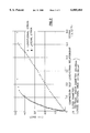
- FIG. 3 is a characteristic graph illustrating an example of load-displacement characteristic obtained by a bending test of the embodiment
- FIG. 4 is a characteristic graph illustrating a relationship between the age of material and the amount of displacement of the embodiment
- FIG. 5 is a characteristic graph illustrating a relationship between the age of material and the temperature and moisture of the embodiment
- FIG. 6 is a characteristic graph illustrating a relationship between the moisture and the amount of displacement of the embodiment
- FIG. 1 is an explanatory view illustrating the constitution of the preferred embodiment.
- an elongate paper strip 2 formed from base paper having 521 g/m 2 of unit weight, 0.72 g/cm 3 of bulk density and 0.7 mm of thickness is spirally wound to form twenty two layers, adjacent parts of successive laminations thereof are bonded by means of polyvinyl alcohol resin type adhesives.
- the paper strip 2 is laminated into a cylindrical shape, and the outside surfaces applied with a water proof treatment with paraffin to form a paper pipe 1 as a building structural member.
- the bulk density is represented as (A/S)/d in which S is the area, A is the mass and d is the thickness d of the paper, so that the bulk density is obtained by dividing the mass per unit area by the thickness d.
- a structure having a compression strength of not less than 250 kg/cm 2 and a peeling strength of not less than 13.0 kg/cm 2 can be obtained.
- the present inventor confirmed that a tent house of 4 m height at a pole can be assembled by using the paper pipe 1 according to the present invention and daily life is possible at the inside of the tent under usual environmental conditions.
- paper pipes 1 applied with a water proof treatment with paraffin, each of 33 cm outer diameter, 15 mm thickness and 4 m height are inserted by the number of 48 into PC bases and arranged along a circle, integrated at upper ends with compressions made of wood, on which a roof of a tent is laid to constitute a tent house.
- the present inventor assembled a hall for holding an exhibition by assembling it out of the paper pipes 1 according to this embodiment and could provide such a hall used for continuous six months with no trouble.
- the roof of the hall was formed with space frames supported by iron frames, a total of three-hundred five paper pipes 1, each of 53 cm outer diameter, 15 mm thickness and 8 m length, are used for all of interior and exterior walls below the space frames, and eighteen paper pipes 1 each of 123 cm outer diameter and 8 m length are used to build a toilet booth.
- a cross-shaped wooden rib set to foundations by anchors is inserted to the base of the paper pipe 1, and the upper end of the pipe is secured by capping a coping prepared by stacking structural plywood sheets to a bolt protruding from the wooden rib.
- the coping is secured with globes of the space frame at each 2 m interval to constitute entire walls.
- the paper pipes 1 themselves can be used as they are for the constituent members of the interior and exterior walls without finishing or without using substrates.
- the weight of the paper pipe 1 of 8 m length is about 130 kg, which is significantly lighter than solid lumber or concrete columns or port employed to present, convenient to transport and can construct buildings efficiently in a short period of time.
- cylindrical paper pipe of circular cross section An example of a cylindrical paper pipe of circular cross section is shown in the illustrated embodiment, but a cylindrical paper pipe of a polygonal cross section may also be used.
- Two types of paper pipes one having an outer diameter of about 150 mm and an inner diameter of about 125 mm and the other having about 100 mm of an outer diameter and about 75 mm of an inner diameter were used as specimens for a compression test as shown in Table 1.
- Five specimens were used for each of the types and paper gages were appended (four in total) at a central portion in the axial direction of the material and a direction perpendicular thereto, to determine Young's modulus and Poisson's ratio.
- FIG. 2 shows an example of measuring data by the load test.
- Paper pipes each of 2 m length, 150 mm outer diameter and 125 mm inner diameter were used by the number of five as shown in Table 3.
- the bending test was conducted by placing a wooden beam on a lower bed of a testing machine, on which both ends of the specimen were supported, a pressure plate was also made as a wooden device, and pressure was applied to a central portion of a specimen by way of the pressure plate at a span of 185 cm and under a load rate of 7 kg/cm 2 /min concentrically.
- the displacement was measured at the positions for the lower bed and the pressure plate, and the fulcrum and the floor position, and a central displacement is defined as a value subtracting the latter from the former.
- FIG. 3 shows an example of load-displacement characteristic obtained by the bending test, and it is shown that the displacement increases linearly as far as the maximum strength.
- Table 4 shows data for the strength and the Young's modulus for each of the specimens obtained by the bending test.
- the resultant average strength is 145 kg/cm 2 , which is 1.65 times as large as the compression strength in a case of a paper pipe of 150 mm outer diameter, while the Young's modules is 1.67 ⁇ 10 4 kg/cm 2 , which is reduced by about 7% than the value obtained by the compression test, which is table to compressible strain at a pressure point.
- a creep test was conducted on five paper pipes 1 each of 400 mm length, 100 mm outer diameter and 75 mm inner diameter. Plates each of 6 mm thickness were set on both ends of the paper pipe 1, bolts were passed through a hole disposed to the central portion of the plate and clamped by a torque wrench until a predetermined torque value was reached. Then, the amount of displacement of the paper pipe 1 was read by attaching an electric dial gage to a lumber material and fitting it between plates. The measurement was conducted substantially at one week interval while clamping to a predetermined torque value before measurement.
- FIG. 4 shows a relationship between the age of material and the amount of displacement obtained by the creep test and
- FIG. 5 shows a relationship between corresponding age of material and room temperature and humidity.
- the displacement was substantially constant at about 0.337 mm on average up to about 100 days of material age, and the displacement was remarkably increased thereafter and reached 1.03 mm at 147 days. Further, as apparent by comparison with FIG. 5, humidity gives an effect on the amount of displacement and the amount of displacement tends to increase as the humidity decreases.
- FIG. 6 is a characteristic graph illustrating a relationship between the humidity and the amount of displacement, clearly showing that the amount of displacement by the creep is reduced at low humidity.
- the paper pipes of this embodiment can be manufactured at a reduced production cost using simple procedures, are light in weight and convenient to transport and can be used for forming various kinds of wall materials in a short period of time when they are used as they are without using substrates, and the paper pipes 1 can be re-used.
- This embodiment enables to construct buildings by simple steps, in a short period of time at a low production cost, and the buildings thus constructed can be used comfortably and efficiently for a long period of time.
- the building structural member comprises a paper strip formed into a cylindrical shape by spirally winding and securing adjacent opposed laminations by means of adhesives, interior and exterior walls of the buildings can be manufactured by using the building structure in simple steps and at a reduced production cost.
- the peeling strength is not less than 13.0 kg/cm 2 and a compression strength is not less than 250 kg/cm 2 according to the present invention, the interior and the exterior walls of buildings can be constructed with sufficient strength.
Abstract
A building structure comprising a paper strip formed into a cylindrical shape by spirally winding the same and securing adjacent opposed portions thereof by means of adhesives. The building structure has a peeling strength of not less than 13.0 kg/cm2 and a compression strength of not less than 250 kg/cm2, which can be used for manufacturing interior and exterior walls of buildings in simple steps, rapidly and at a reduced manufacturing cost.
Description
This is a continuation of my co-pending U.S. patent application Ser. No. 08/685,247, filed Jul. 23, 1996, now abandoned.
1. Field of the Invention
The present invention concerns a building structure and, more specifically, it relates to a building structural member or element capable of constituting interior or exterior walls of buildings.
2. Description of the Prior Arts
There are buildings such as a meeting hall, not to be used for a long time after construction but used only for a relatively short period of term for holding entertainments and then dismantled after use, or buildings such as a tent or a medical facility disposed in refugee's camp to be used for a predetermined period of term and then dismantled and carried back. It is desirable for the construction of such buildings to use building structural member or element which are light in weight and which convenient to transport and can be manufactured at as low production cost as possible.
Heretofore, solid lumber or concrete, port or pillows have been used as building structural members capable of constituting interior and exterior walls of buildings, and the interior and exterior walls for the buildings are constituted by arranging such building structural element in a row side by side.
However, the existent building structural member described above is considerably heavy in weight and inconvenient to transport, requires much labor and time for construction, and as well as creates a problem also in the re-use of them after dismantling.
The present invention has been accomplished in view of the present situations for the building structural member of the aforementioned type and it is an object of the invention to provide a building structural members which is light in weight, can be manufactured at a low production cost and can be used for assembling into various shapes of interior and exterior walls of buildings in simple steps and in a short period of time.
For attaining the foregoing object, in accordance with an aspect of the present invention, there is provided a building structural member comprising a post pillar, or rod formed from a paper strip wound a cylindrical shape by spirally winding the strip and securing adjacent successive laminations thereof to each other with adhesives.
In a preferred embodiment, the building structural member described above has a peeling strength of not less than 13.0 kg/cm2 and a compression strength of not less than 250 kg/cm2.
The building structural member according to the present invention comprises structural support member formed of a paper strip wound into a cylindrical shape by spirally winding the same and securing adjacent successive laminations by means of adhesives, and the building structure member can be used for creating interior and exterior walls of buildings in simple steps.
The building structure member in the preferred embodiment of the present invention comprises a general cylindrical port formed of a paper strip wound into a cylindrical shape by spirally winding the paper strip and securing adjacent susscesive laminations by means of adhesives. The paper strip has a peeling strength of not less than 13.0 kg/cm2 and a compression strength of not less than 250 kg/cm2, and the building structural member can be used for interior and exterior walls of buildings with sufficient strength.
FIG. 1 is an explanatory view illustrating the constitution of a preferred embodiment according to the present invention;
FIG. 2 is a characteristic graph illustrating an example of load-strain characteristic obtained by a compression test of the embodiment;
FIG. 3 is a characteristic graph illustrating an example of load-displacement characteristic obtained by a bending test of the embodiment;
FIG. 4 is a characteristic graph illustrating a relationship between the age of material and the amount of displacement of the embodiment;
FIG. 5 is a characteristic graph illustrating a relationship between the age of material and the temperature and moisture of the embodiment;
FIG. 6 is a characteristic graph illustrating a relationship between the moisture and the amount of displacement of the embodiment;
The present invention is to be explained by way of a preferred embodiment with reference to FIG. 1.
FIG. 1 is an explanatory view illustrating the constitution of the preferred embodiment.
In the present invention, as shown in FIG. 1, an elongate paper strip 2 formed from base paper having 521 g/m2 of unit weight, 0.72 g/cm3 of bulk density and 0.7 mm of thickness is spirally wound to form twenty two layers, adjacent parts of successive laminations thereof are bonded by means of polyvinyl alcohol resin type adhesives. The paper strip 2 is laminated into a cylindrical shape, and the outside surfaces applied with a water proof treatment with paraffin to form a paper pipe 1 as a building structural member. The bulk density is represented as (A/S)/d in which S is the area, A is the mass and d is the thickness d of the paper, so that the bulk density is obtained by dividing the mass per unit area by the thickness d.
In the present invention of the above-mentioned constitution, a structure having a compression strength of not less than 250 kg/cm2 and a peeling strength of not less than 13.0 kg/cm2 can be obtained.
The present inventor confirmed that a tent house of 4 m height at a pole can be assembled by using the paper pipe 1 according to the present invention and daily life is possible at the inside of the tent under usual environmental conditions. In this case, paper pipes 1 applied with a water proof treatment with paraffin, each of 33 cm outer diameter, 15 mm thickness and 4 m height are inserted by the number of 48 into PC bases and arranged along a circle, integrated at upper ends with compressions made of wood, on which a roof of a tent is laid to constitute a tent house.
Further, the present inventor assembled a hall for holding an exhibition by assembling it out of the paper pipes 1 according to this embodiment and could provide such a hall used for continuous six months with no trouble. In this case, the roof of the hall was formed with space frames supported by iron frames, a total of three-hundred five paper pipes 1, each of 53 cm outer diameter, 15 mm thickness and 8 m length, are used for all of interior and exterior walls below the space frames, and eighteen paper pipes 1 each of 123 cm outer diameter and 8 m length are used to build a toilet booth. A cross-shaped wooden rib set to foundations by anchors is inserted to the base of the paper pipe 1, and the upper end of the pipe is secured by capping a coping prepared by stacking structural plywood sheets to a bolt protruding from the wooden rib. The coping is secured with globes of the space frame at each 2 m interval to constitute entire walls.
In the construction of the buildings using the paper pipes 1 of the embodiment, the paper pipes 1 themselves can be used as they are for the constituent members of the interior and exterior walls without finishing or without using substrates. The weight of the paper pipe 1 of 8 m length is about 130 kg, which is significantly lighter than solid lumber or concrete columns or port employed to present, convenient to transport and can construct buildings efficiently in a short period of time.
An example of a cylindrical paper pipe of circular cross section is shown in the illustrated embodiment, but a cylindrical paper pipe of a polygonal cross section may also be used.
Explanation is to be made for a strength test conducted for this embodiment.
(1) Compression Test
Two types of paper pipes, one having an outer diameter of about 150 mm and an inner diameter of about 125 mm and the other having about 100 mm of an outer diameter and about 75 mm of an inner diameter were used as specimens for a compression test as shown in Table 1. Five specimens were used for each of the types and paper gages were appended (four in total) at a central portion in the axial direction of the material and a direction perpendicular thereto, to determine Young's modulus and Poisson's ratio.
              TABLE 1
______________________________________
Dimension for Specimen
a:  Paper pipe of   a*     Paper pipe of
    150 mm outer diameter, 100 mm outer diameter,
    125 mm inner diameter  75 mm inner diameter
                     Cross                  Cross
     Outer   Inner   sectional   Outer Inner
                                            sectional
     dia     dia     area        dia   dia  area
No.  mm      mm      cm.sup.2
                            No.  mm    mm   cm.sup.2
______________________________________
1    150.75  124.69  56.38  1    99.78 75.07
                                            33.259
2    150.76  124.78  56.22  2    99.84 75.16
                                            33.495
3    150.78  124.86  56.11  3    99.64 75.16
                                            33.495
4    150.80  124.84  56.20  4    99.75 75.05
                                            33.200
5    150.84  124.72  56.53  5    99.88 75.22
                                            33.653
______________________________________
A compression test was conducted by placing a ball seat to a lower bed, laying a plate and setting a specimen thereon and laying a plate also on the upper end of the specimen, and under a load rate of 2-4 kg/cm2 /min. FIG. 2 shows an example of measuring data by the load test.
The data for each of the test specimens and average data obtained from the specimen of each of the sizes in the compression test are as shown in Table 2.
              TABLE 2
______________________________________
Result of Compression Test
                                   E
Specimen A        P       σmax
                                   (x10.sup.4
No.      (cm.sup.2)
                  (kg)    (kg/cm.sup.2)
                                   kg/cm.sup.2)
                                         υ
______________________________________
a-1      56.38    4840    85.8     1.76  0.125
a-2      56.22    4700    83.6     1.69  0.135
a-3      56.11    5215    92.9     1.90  0.169
a-4      56.20    5110    90.9     1.73  0.169
a-5      56.53    4975    88.0     1.87  0.187
Average                   88.2     1.79  0.157
a*-1     33.26    3335    100.3    1.86  0.192
a*-2     33.50    3640    108.7    --    --
a*-3     33.50    3405    101.7    1.88  0.180
a*-4     33.20    3452.5  104.0    1.89  0.197
a*-5     33.65    3405    101.2    1.82  0.187
Average                   103.2    1.86  0.187
______________________________________
(2) Bending Test
Paper pipes each of 2 m length, 150 mm outer diameter and 125 mm inner diameter were used by the number of five as shown in Table 3.
              TABLE 3
______________________________________
Size of Specimen
                            Geometrical
                            moment of
          Outer   Inner     second  Section
Specimen  dia     dia       order   modulus
No.       (mm)    (mm)      (cm.sup.2)
                                    (cm.sup.3)
______________________________________
b-1       150.33  124.91    1312.01 174.55
b-2       150.40  124.90    1317.07 175.14
b-3       150.26  124.72    1414.60 174.98
b-4       150.29  124.83    1312.41 174.65
b-5       150.54  124.08    1319.53 175.31
______________________________________
The bending test was conducted by placing a wooden beam on a lower bed of a testing machine, on which both ends of the specimen were supported, a pressure plate was also made as a wooden device, and pressure was applied to a central portion of a specimen by way of the pressure plate at a span of 185 cm and under a load rate of 7 kg/cm2 /min concentrically. The displacement was measured at the positions for the lower bed and the pressure plate, and the fulcrum and the floor position, and a central displacement is defined as a value subtracting the latter from the former.
According to the bending test, occurrence of wrinkles is observed along a winding angle of the elongate paper strip 2 at the upper end undergoing bending compression.
FIG. 3 shows an example of load-displacement characteristic obtained by the bending test, and it is shown that the displacement increases linearly as far as the maximum strength.
Table 4 shows data for the strength and the Young's modulus for each of the specimens obtained by the bending test. The resultant average strength is 145 kg/cm2, which is 1.65 times as large as the compression strength in a case of a paper pipe of 150 mm outer diameter, while the Young's modules is 1.67×10⁴ kg/cm2, which is reduced by about 7% than the value obtained by the compression test, which is table to compressible strain at a pressure point.
              TABLE 4
______________________________________
Result of Bending Test
                                       E
Specimen I        Z      Pmax   σmas
                                       (x10.sup.4
No.      (cm.sup.2)
                  (cm.sup.3)
                         (kg)   kg/cm.sup.2)
                                       kg/m.sup.2)
______________________________________
1        1312     174.5  567.5  150    1.74
2        1317     175.1  549.0  145    1.62
3        1315     175.0  513.0  136    1.64
4        1312     174.6  576.0  153    1.72
5        1320     175.4  540.5  143    1.65
Average                         145    1.67
______________________________________
(3) Creep Test
A creep test was conducted on five paper pipes 1 each of 400 mm length, 100 mm outer diameter and 75 mm inner diameter. Plates each of 6 mm thickness were set on both ends of the paper pipe 1, bolts were passed through a hole disposed to the central portion of the plate and clamped by a torque wrench until a predetermined torque value was reached. Then, the amount of displacement of the paper pipe 1 was read by attaching an electric dial gage to a lumber material and fitting it between plates. The measurement was conducted substantially at one week interval while clamping to a predetermined torque value before measurement.
FIG. 4 shows a relationship between the age of material and the amount of displacement obtained by the creep test and FIG. 5 shows a relationship between corresponding age of material and room temperature and humidity.
As shown in FIG. 4, the displacement was substantially constant at about 0.337 mm on average up to about 100 days of material age, and the displacement was remarkably increased thereafter and reached 1.03 mm at 147 days. Further, as apparent by comparison with FIG. 5, humidity gives an effect on the amount of displacement and the amount of displacement tends to increase as the humidity decreases.
FIG. 6 is a characteristic graph illustrating a relationship between the humidity and the amount of displacement, clearly showing that the amount of displacement by the creep is reduced at low humidity.
As has been described above, the paper pipes of this embodiment can be manufactured at a reduced production cost using simple procedures, are light in weight and convenient to transport and can be used for forming various kinds of wall materials in a short period of time when they are used as they are without using substrates, and the paper pipes 1 can be re-used. This embodiment enables to construct buildings by simple steps, in a short period of time at a low production cost, and the buildings thus constructed can be used comfortably and efficiently for a long period of time.
As has been described above according to the present invention, since the building structural member comprises a paper strip formed into a cylindrical shape by spirally winding and securing adjacent opposed laminations by means of adhesives, interior and exterior walls of the buildings can be manufactured by using the building structure in simple steps and at a reduced production cost.
In addition to the above-mentioned advantageous effects, since the peeling strength is not less than 13.0 kg/cm2 and a compression strength is not less than 250 kg/cm2 according to the present invention, the interior and the exterior walls of buildings can be constructed with sufficient strength.
Claims (4)
1. A tubular structural member adapted for supporting a vertical axial load, comprising an elongated paper strip that is spirally wound as a seamless cylindrical member formed of a plurality of laminations, and an adhesive applied between successive laminations of said spirally wound paper strip so that said tubular structural member is substantially rigid, wherein said paper strip and said adhesive are selected such that the tubular structural element has a peeling strength of not less than 13.0 kg/cm2 and a compression strength of not less than 250 kg/cm2 ; and a waterproof treatment applied onto an outer surface of the tubular structural member and covering substantially the entire outer surface thereof.
2. The tubular structural member of claim 1 wherein said waterproof treatment includes a paraffin.
3. A tubular structural member comprising an elongated paper strip that is spirally wound as a seamless cylindrical member formed of a plurality of laminations, wherein said elongated paper strip forms all said laminations, and an adhesive applied between successive laminations of said spirally wound paper strip so that said tubular structural member is substantially rigid wherein said paper strip and said adhesive are selected such that the tubular structural element has a peeling strength of not less than 13.0 kg/cm2 and a compression strength of not less than 250 kg/cm2 ; and a waterproof treatment applied onto an outer surface of said tubular structural member and covering substantially the entire outer surface thereof.
4. The tubular structural member of claim 3, wherein said waterproof treatment includes a paraffin.
Priority Applications (1)
| Application Number | Priority Date | Filing Date | Title |
|---|---|---|---|
| US09/393,494 US6085484A (en) | 1995-01-18 | 1999-09-10 | Building structure |
Applications Claiming Priority (4)
| Application Number | Priority Date | Filing Date | Title |
|---|---|---|---|
| JP7-23488 | 1995-01-18 | ||
| JP07023488A JP3125841B2 (en) | 1995-01-18 | 1995-01-18 | Building structures |
| US68524796A | 1996-07-23 | 1996-07-23 | |
| US09/393,494 US6085484A (en) | 1995-01-18 | 1999-09-10 | Building structure |
Related Parent Applications (1)
| Application Number | Title | Priority Date | Filing Date |
|---|---|---|---|
| US68524796A Continuation-In-Part | 1995-01-18 | 1996-07-23 |
Publications (1)
| Publication Number | Publication Date |
|---|---|
| US6085484A true US6085484A (en) | 2000-07-11 |
Family
ID=26360849
Family Applications (1)
| Application Number | Title | Priority Date | Filing Date |
|---|---|---|---|
| US09/393,494 Expired - Fee Related US6085484A (en) | 1995-01-18 | 1999-09-10 | Building structure |
Country Status (1)
| Country | Link |
|---|---|
| US (1) | US6085484A (en) |
Cited By (1)
| Publication number | Priority date | Publication date | Assignee | Title |
|---|---|---|---|---|
| US20070044407A1 (en) * | 2005-08-30 | 2007-03-01 | Specialty Hardware L.P. | Fire-retardant cementitious shear board having metal backing with tab for use as underlayment panel for floor or roof |
Citations (2)
| Publication number | Priority date | Publication date | Assignee | Title |
|---|---|---|---|---|
| US4462556A (en) * | 1983-03-31 | 1984-07-31 | Sonoco Products Company | Tube with reinforcing strip |
| US5131325A (en) * | 1991-04-30 | 1992-07-21 | Flexographic Technology, Inc. | Reusable printing sleeve |
-
1999
- 1999-09-10 US US09/393,494 patent/US6085484A/en not_active Expired - Fee Related
Patent Citations (2)
| Publication number | Priority date | Publication date | Assignee | Title |
|---|---|---|---|---|
| US4462556A (en) * | 1983-03-31 | 1984-07-31 | Sonoco Products Company | Tube with reinforcing strip |
| US5131325A (en) * | 1991-04-30 | 1992-07-21 | Flexographic Technology, Inc. | Reusable printing sleeve |
Cited By (4)
| Publication number | Priority date | Publication date | Assignee | Title |
|---|---|---|---|---|
| US20070044407A1 (en) * | 2005-08-30 | 2007-03-01 | Specialty Hardware L.P. | Fire-retardant cementitious shear board having metal backing with tab for use as underlayment panel for floor or roof |
| US20100192510A1 (en) * | 2005-08-30 | 2010-08-05 | Specialty Hardware L.P. | Fire-Retardant Cementitious Shear Board Having Metal Backing with Tab for Use as Underlayment Panel for Floor or Roof |
| US7770346B2 (en) | 2005-08-30 | 2010-08-10 | Specialty Hardware L.P. | Fire-retardant cementitious shear board having metal backing with tab for use as underlayment panel for floor or roof |
| US7823364B2 (en) | 2005-08-30 | 2010-11-02 | Specialty Hardware L.P. | Fire-retardant cementitious shear board having metal backing with tab for use as underlayment panel for floor or roof |
Similar Documents
| Publication | Publication Date | Title |
|---|---|---|
| US20190161972A1 (en) | Self supportive panel system | |
| CA2104175C (en) | Building block; system and method for construction using same | |
| US4249354A (en) | Reinforced insulated wall construction | |
| US6718712B1 (en) | Structural panel and method of fabrication | |
| US3228822A (en) | Tubular core partition panel | |
| DK2773819T3 (en) | Construction unit for immediate or permanent shelter | |
| US5761863A (en) | Method of reinforcing a building | |
| CA2156488A1 (en) | Fiber-bale composite structural system and method | |
| WO1997037090A1 (en) | Unitized post and panel building system | |
| AU2003271053A1 (en) | Wall construction of architectural structure | |
| US20200232205A1 (en) | System, method and apparatus for integrated portable building foundation platform with modular components | |
| US20170241127A1 (en) | Bamboo Pole Connectors for Building Construction | |
| US4285179A (en) | Plate shaped prefabricated guilding element and a process for the production of walls by using these elements | |
| KR20170117049A (en) | Interlocking structure Block strengthening means and modular construction system | |
| US20070062134A1 (en) | Cellularcrete wall system | |
| US6085484A (en) | Building structure | |
| US20210363753A1 (en) | Prefabricated wall panel, manufacturing method and structural system | |
| US5566520A (en) | Integrated precast concrete forming system | |
| JP6403025B1 (en) | Steel column-beam joint structure and wooden structure | |
| US20060016146A1 (en) | Structural panel and method of fabrication | |
| JP3125841B2 (en) | Building structures | |
| US20210388602A1 (en) | Building Structure and Method of Construction | |
| US7390186B2 (en) | Structural building panels, apparatus and method for fabricating structural building panels | |
| KR100321140B1 (en) | wall form structure | |
| CN219261338U (en) | Rod-type yurt skeleton texture |
Legal Events
| Date | Code | Title | Description |
|---|---|---|---|
| CC | Certificate of correction | ||
| REMI | Maintenance fee reminder mailed | ||
| LAPS | Lapse for failure to pay maintenance fees | ||
| FP | Lapsed due to failure to pay maintenance fee |
Effective date: 20040711 |
|
| STCH | Information on status: patent discontinuation |
Free format text: PATENT EXPIRED DUE TO NONPAYMENT OF MAINTENANCE FEES UNDER 37 CFR 1.362 |