US6085586A - Flow meter system with remote displays for each discharge - Google Patents
Flow meter system with remote displays for each discharge Download PDFInfo
- Publication number
- US6085586A US6085586A US09/159,946 US15994698A US6085586A US 6085586 A US6085586 A US 6085586A US 15994698 A US15994698 A US 15994698A US 6085586 A US6085586 A US 6085586A
- Authority
- US
- United States
- Prior art keywords
- flow
- flow meter
- microprocessor
- volume rate
- fluid
- Prior art date
- Legal status (The legal status is an assumption and is not a legal conclusion. Google has not performed a legal analysis and makes no representation as to the accuracy of the status listed.)
- Expired - Lifetime
Links
- 238000011144 upstream manufacturing Methods 0.000 claims abstract description 11
- 230000000007 visual effect Effects 0.000 claims abstract description 7
- 239000012530 fluid Substances 0.000 claims description 15
- 239000007788 liquid Substances 0.000 abstract description 10
- 238000012544 monitoring process Methods 0.000 abstract description 2
- XLYOFNOQVPJJNP-UHFFFAOYSA-N water Substances O XLYOFNOQVPJJNP-UHFFFAOYSA-N 0.000 description 30
- 239000006260 foam Substances 0.000 description 8
- 239000012141 concentrate Substances 0.000 description 6
- 238000010586 diagram Methods 0.000 description 4
- 238000002347 injection Methods 0.000 description 3
- 239000007924 injection Substances 0.000 description 3
- 239000004020 conductor Substances 0.000 description 2
- 230000008878 coupling Effects 0.000 description 2
- 238000010168 coupling process Methods 0.000 description 2
- 238000005859 coupling reaction Methods 0.000 description 2
- 238000013461 design Methods 0.000 description 2
- 238000006073 displacement reaction Methods 0.000 description 2
- 239000000203 mixture Substances 0.000 description 2
- 230000009182 swimming Effects 0.000 description 2
- PMMYEEVYMWASQN-DMTCNVIQSA-N Hydroxyproline Chemical compound O[C@H]1CN[C@H](C(O)=O)C1 PMMYEEVYMWASQN-DMTCNVIQSA-N 0.000 description 1
- 239000003990 capacitor Substances 0.000 description 1
- 238000010276 construction Methods 0.000 description 1
- 238000001914 filtration Methods 0.000 description 1
- 230000001939 inductive effect Effects 0.000 description 1
- 238000012986 modification Methods 0.000 description 1
- 230000004048 modification Effects 0.000 description 1
- 238000011017 operating method Methods 0.000 description 1
- 230000001105 regulatory effect Effects 0.000 description 1
- 239000004065 semiconductor Substances 0.000 description 1
- 238000007493 shaping process Methods 0.000 description 1
- 239000000126 substance Substances 0.000 description 1
Images

Classifications
-
- A—HUMAN NECESSITIES
- A62—LIFE-SAVING; FIRE-FIGHTING
- A62C—FIRE-FIGHTING
- A62C5/00—Making of fire-extinguishing materials immediately before use
- A62C5/02—Making of fire-extinguishing materials immediately before use of foam
-
- G—PHYSICS
- G01—MEASURING; TESTING
- G01F—MEASURING VOLUME, VOLUME FLOW, MASS FLOW OR LIQUID LEVEL; METERING BY VOLUME
- G01F1/00—Measuring the volume flow or mass flow of fluid or fluent solid material wherein the fluid passes through a meter in a continuous flow
- G01F1/05—Measuring the volume flow or mass flow of fluid or fluent solid material wherein the fluid passes through a meter in a continuous flow by using mechanical effects
- G01F1/053—Measuring the volume flow or mass flow of fluid or fluent solid material wherein the fluid passes through a meter in a continuous flow by using mechanical effects using rotating vanes with tangential and axial admission
-
- G—PHYSICS
- G01—MEASURING; TESTING
- G01F—MEASURING VOLUME, VOLUME FLOW, MASS FLOW OR LIQUID LEVEL; METERING BY VOLUME
- G01F15/00—Details of, or accessories for, apparatus of groups G01F1/00 - G01F13/00 insofar as such details or appliances are not adapted to particular types of such apparatus
- G01F15/07—Integration to give total flow, e.g. using mechanically-operated integrating mechanism
- G01F15/075—Integration to give total flow, e.g. using mechanically-operated integrating mechanism using electrically-operated integrating means
- G01F15/0755—Integration to give total flow, e.g. using mechanically-operated integrating mechanism using electrically-operated integrating means involving digital counting
Definitions
- This invention relates generally to apparatus for monitoring the volume of liquid being drawn from a supply by way of several discharge conduits, and more particularly to a network flow meter devices interconnected to provide indications of volume rate of flow and total flow from each of the plurality of discharge conduits and the total flow from all such discharge conduits.
- a so-called mid-ship pump is used to deliver water at high pressure and flow rates to a plurality of discharge conduits on the fire truck.
- a truck may, for example, have a water cannon for delivering water at up to 1,000 gallons per minute, several 13/4 to 21/2 inch diameter attack hoses for directing water onto burning structures at up to 120 gallons per minute and 1 inch diameter hand lines for extinguishing smaller fires and extinguishing "hot-spots" once the fire has been brought under control.
- hand lines may deliver 60 to 90 gallons/minute.
- U.S. Pat. Nos. 5,313,548; 5,232,052; 5,494,112 and RE 35,362 owned by applicants, assignee describe a computer-based system for delivering metered quantities of foam concentrate to a water stream so as to maintain the desired concentration.
- the system includes a positive displacement pump and a drive motor therefore whose speed can be varied over a wide range to deliver a foam concentrate from a supply tank thereof to a discharge conduit.
- a flow meter transducer Associated with the main discharge conduit is a flow meter transducer that feeds information into a microprocessor as to the existing flow rate of liquid through the main discharge conduit and this information is processed to cause the motor to drive the foam concentrate pump at a rate to maintain a preprogrammed foam/water concentration in the stream being delivered out the discharge conduit.
- a visual display panel which is used to provide a visual indication to the operator of the volume rate of flow and the total flow during a given time period.
- each individual discharge conduit may have its own flow meter transducer and circuitry for displaying the volume rate of flow and total flow out each of the plural discharge conduits. Moreover, it is advantageous that provision be made for computing and displaying the total flow out of all of the plural discharge conduits. This allows a fire fighter on board a fire truck to more readily monitor the volume of water being directed on to a fire and the rate at which an existing supply is being exhausted.
- the present invention provides a system for measuring and displaying the volume of a liquid being drawn from a supply by way of a plurality of discharge conduits.
- Each of the discharge conduits has associated with it a flow meter circuit that includes a flow transducer for producing pulses at a frequency proportional to the rate of flow of liquid through its associated discharge conduit.
- Each of the flow meter circuits is connected in a series configuration and each of the flow meter circuits includes microprocessor means that counts the pulses from the flow transducers and converts the count to volume rate of flow data and total flow data.
- the first microprocessor has an input for receiving pulses from its associated flow transducer and an output for delivering the volume rate of flow data proportional to the pulse count.
- the second microprocessor includes a first input coupled to the output of the first microprocessor and a second input for receiving the volume rate of flow data from the adjacent upstream flow meter circuit and an output for delivering the combined volume rate of flow value to its adjacent downstream flow meter circuit.
- FIG. 1 is a schematic diagram of a fluid handling system with which the present invention finds application;
- FIG. 2 is a schematic electrical diagram of a flow meter system showing a plurality of flow meter circuits connected in series with one another and to a controller;
- the water supply need not be a tank, as at 10, but may just as well comprise a supply of water, such as a residential swimming pool, or any other supply of water, such as a lake or pond.
- each of the flow meter transducers 36 feeds the pulses to an associated flow meter circuit as at 38, 40 and 42.
- the flow meter circuits each include an alpha/numeric display panel 44 and manually operable push-button switches 46 and 48, allowing an operator to selectively display the volume rate of flow through a particular discharge conduit, as well as the total flow through that conduit over a predetermined time interval.
- the push-button for selecting rate of flow is labeled "R" and that used for displaying total flow by the letter "T".
- each of the flow meter circuits is able to receive flow information from an adjacent upstream flow meter circuit, combine that information with flow information derived from its own flow meter transducer and pass the combined flow information on to an adjacent downstream flow meter circuit.
- the flow meter circuits 38, 40 and 42 are only able to provide a visual display of rate of flow and total flow derived from its own flow meter transducer 36.
- the controller 34 displays the rate of flow and total flow for all of the discharge conduits as combined or total quantities, i.e., the sum of the individual readings from all of the flow meter circuits used in the system.
- the individual flow meter circuits 38, 40, 42 may be separately located on the fire truck, but preferably will be clustered at a main control panel along with the controller 34 including a display 50 so that the fire captain can read at a glance the volume rate of flow and the total flow exiting each of the discharge conduits, as well as the rate of flow and total flow for all of the discharge conduits combined.
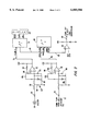
- FIG. 3 is an electrical schematic diagram of the circuitry employed in implementing each of the individual flow meter circuits 38, 40 and 42. Not shown in FIG. 3 is the power supply for converting the output of the fire truck's generator to a filtered and regulated DC output of +5 volts that is used to power the circuitry illustrated. Such power supplies are entirely conventional and need not be described herein because persons of ordinary skill in electronic design are able to devise a DC-to-DC switching regulator capable of converting either a 12 volt DC supply or a 24 volt DC supply down to a 5 volt level.
- the flow information computed by the microprocessor 72 is also delivered by way of a serial bus 74 to an input of a second microprocessor 76, along with pulse count information from an adjacent upstream flow meter.
- the second microprocessor 76 is programmed to sum the flow information from the upstream flow meter circuits with the flow information derived from its own flow meter transducer to produce an output equal to the resulting total.
- This combined flow information is then passed on to an adjacent downstream flow meter circuit. More particularly, the previous or combined flow from an adjacent upstream flow meter circuit is applied via a coupling resistor 78 and a filtering and shaping circuit 80 to the inverting input of a comparitor 82. Without limitation, it may comprise a Type LM339 comparitor chip.
- the comparitor 82 has a feedback network including resistor 84 and the voltage divider comprising series connected resistors 86 and 88. The output from the comparitor 82 is connected to an input pin of the second microprocessor 76 via connector 90.
- the combined flow information from the second microprocessor 76 is applied, via a conductor 92, to an non-inverting input of an op amp 94 that is configured to function as a cable driver whereby the combined flow pulse count information may be delivered to the input terminal 77 of the adjacent downstream flow meter circuit, via cable 96.
- an op amp 94 that is configured to function as a cable driver whereby the combined flow pulse count information may be delivered to the input terminal 77 of the adjacent downstream flow meter circuit, via cable 96.
- the input to the controller module 34 comprises a combined outputs from each of the plurality of flow meter circuits 38, 40, 42, etc., and based upon the total pulse count information which it receives, the microprocessor contained therein may compute the combined flow rate from all of the discharge conduits as well as the total flow from the plurality of conduits during a predetermined time interval.
Abstract
Description
Claims (2)
Priority Applications (1)
| Application Number | Priority Date | Filing Date | Title |
|---|---|---|---|
| US09/159,946 US6085586A (en) | 1998-09-24 | 1998-09-24 | Flow meter system with remote displays for each discharge |
Applications Claiming Priority (1)
| Application Number | Priority Date | Filing Date | Title |
|---|---|---|---|
| US09/159,946 US6085586A (en) | 1998-09-24 | 1998-09-24 | Flow meter system with remote displays for each discharge |
Publications (1)
| Publication Number | Publication Date |
|---|---|
| US6085586A true US6085586A (en) | 2000-07-11 |
Family
ID=22574786
Family Applications (1)
| Application Number | Title | Priority Date | Filing Date |
|---|---|---|---|
| US09/159,946 Expired - Lifetime US6085586A (en) | 1998-09-24 | 1998-09-24 | Flow meter system with remote displays for each discharge |
Country Status (1)
| Country | Link |
|---|---|
| US (1) | US6085586A (en) |
Cited By (27)
| Publication number | Priority date | Publication date | Assignee | Title |
|---|---|---|---|---|
| WO2003042092A1 (en) * | 2001-11-09 | 2003-05-22 | Thomas Boyle | Method and system for testing foam-water fire protection systems |
| US6613236B1 (en) * | 1999-06-30 | 2003-09-02 | Whirlpool Corporation | Water filter monitoring and indicating system |
| US6620161B2 (en) | 2001-01-24 | 2003-09-16 | Ethicon, Inc. | Electrosurgical instrument with an operational sequencing element |
| US6802370B1 (en) * | 2002-08-27 | 2004-10-12 | The United States Of America As Represented By The Secretary Of The Navy | Personal cooling system for shipboard firefighters |
| US20050045345A1 (en) * | 2003-08-29 | 2005-03-03 | Hypro Corporation | High flow foam system for fire fighting applications |
| WO2005021098A2 (en) * | 2003-08-29 | 2005-03-10 | Kidde Fire Fighting, Inc. | High flow mobile fire fighting system |
| US20050155776A1 (en) * | 2002-09-20 | 2005-07-21 | Hypro Corporation | Fire fighting foam injection system with auto-start feature |
| US20060032939A1 (en) * | 2004-08-10 | 2006-02-16 | Crash Rescue Equipment Service, Inc. | Fire retardant management system |
| US20060117676A1 (en) * | 2004-11-19 | 2006-06-08 | Robert Chaput | Roof cooling system |
| US20080017664A1 (en) * | 2006-07-20 | 2008-01-24 | Haste Thomas E | Aerosol metering apparatus |
| US20080142615A1 (en) * | 2006-12-18 | 2008-06-19 | Ho-Chin Chen | Water flow volume display device for watering nozzle |
| US20080185159A1 (en) * | 2007-02-06 | 2008-08-07 | City Of Chicago | Foam fire suppression apparatus |
| US20090105969A1 (en) * | 2007-10-23 | 2009-04-23 | Saylor David J | Method and Device for the Assessment of Fluid Collection Networks |
| US20090260836A1 (en) * | 2008-04-09 | 2009-10-22 | Hale Products, Inc. | Integrated Controls For A Fire Suppression System |
| US7739921B1 (en) * | 2007-08-21 | 2010-06-22 | The United States Of America As Represented By The Secretary Of The Navy | Parameter measurement/control for fluid distribution systems |
| US20100302061A1 (en) * | 2003-06-13 | 2010-12-02 | Arad Measuring Technologies Ltd. | Meter Register and Remote Meter Reader Utilizing a Stepper Motor |
| US7997348B2 (en) | 2008-01-03 | 2011-08-16 | Sta-Rite Industries, Llc | Foam proportioning system with low-end controller |
| US20110266011A1 (en) * | 2009-09-16 | 2011-11-03 | Woo Sung Lee | Mobile tube nozzle firefighting sensor pump for a firefighting product for preventing disasters |
| GB2485785A (en) * | 2010-11-23 | 2012-05-30 | Tsi Flowmeters Ltd | A fire appliance vehicle comprising a flow recording system |
| US20120279731A1 (en) * | 2011-05-06 | 2012-11-08 | Howard Sr John Wayne | Rain maker wildfire protection and containment system |
| US20150075821A1 (en) * | 2012-12-20 | 2015-03-19 | Victaulic Company | Dry sprinkler |
| US20150330818A1 (en) * | 2011-03-18 | 2015-11-19 | Soneter, Inc. | Methods and apparatus for fluid flow measurement |
| US20170368719A1 (en) * | 2016-06-24 | 2017-12-28 | Charles Allan Jones | Manifold assembly for resin infusion and injection |
| US10046189B2 (en) | 2014-10-07 | 2018-08-14 | Akron Brass Company | Network controllable pressure governor |
| US10072762B2 (en) | 2014-09-22 | 2018-09-11 | Pentair Flow Technologie, LLC | Adapter valve assembly |
| US10143872B2 (en) | 2011-05-27 | 2018-12-04 | Victaulic Company | Flexible dry sprinkler |
| US11123587B2 (en) * | 2018-03-31 | 2021-09-21 | Barracuda Environmental Services Inc. | On-board mixing system for firefighting chemicals |
Citations (18)
| Publication number | Priority date | Publication date | Assignee | Title |
|---|---|---|---|---|
| US35362A (en) * | 1862-05-27 | Improved corkscrew | ||
| US3949207A (en) * | 1973-04-19 | 1976-04-06 | Oxy Metal Industries Corporation | Installation for the delivery of liquids |
| US4084748A (en) * | 1977-01-04 | 1978-04-18 | Jack W. Anderson | Spray sensing system |
| US4495488A (en) * | 1980-09-05 | 1985-01-22 | Chevron Research Company | Ultrasensitive apparatus and positioning method for detecting change in fluid flow conditions in relief flowlines associated with a chemical or refinery complex |
| US4682711A (en) * | 1985-04-08 | 1987-07-28 | Nordson Corporation | Method and apparatus for sealing welded seams of automobiles |
| US4719574A (en) * | 1985-11-18 | 1988-01-12 | Accurate Metering Systems, Inc. | Batch control system |
| US4736871A (en) * | 1986-11-19 | 1988-04-12 | Luciani Dorian E | Liquid measuring dispenser |
| US4986782A (en) * | 1989-11-24 | 1991-01-22 | Severtson Lyndon W | Liquid flow detector system |
| US5029100A (en) * | 1989-12-15 | 1991-07-02 | Gilbarco Inc. | Blender system for fuel dispenser |
| US5232052A (en) * | 1993-02-09 | 1993-08-03 | Hypro Corporation | Apparatus and method for controlling the introduction of chemical foamant into a water stream in fire-fighting equipment |
| US5303845A (en) * | 1991-08-14 | 1994-04-19 | Yugen Gaisha Yakiniku Restaurant Daiko | Beer self-service system |
| US5310114A (en) * | 1992-09-16 | 1994-05-10 | Cann Roger S | Apparatus and method for measuring paint usage in a painting system |
| US5494112A (en) * | 1993-10-29 | 1996-02-27 | Hypro Corporation | System for introduction of concentrated liquid chemical foamant into a water stream for fighting fires |
| US5540102A (en) * | 1992-09-23 | 1996-07-30 | Kindrick; Dudley | System for displaying the amount of fluid dispensed from a hand-held sprayer |
| US5739429A (en) * | 1995-07-13 | 1998-04-14 | Nordson Corporation | Powder coating system incorporating improved method and apparatus for monitoring flow rate of entrained particulate flow |
| US5927603A (en) * | 1997-09-30 | 1999-07-27 | J. R. Simplot Company | Closed loop control system, sensing apparatus and fluid application system for a precision irrigation device |
| US5927400A (en) * | 1995-06-06 | 1999-07-27 | Eltek S.P.A. | Device and method for the adjustment of the flow rate of a liquid, with closed loop control |
| US5986573A (en) * | 1995-11-20 | 1999-11-16 | Water Savers, Inc. | Method and apparatus for metering building structures |
-
1998
- 1998-09-24 US US09/159,946 patent/US6085586A/en not_active Expired - Lifetime
Patent Citations (19)
| Publication number | Priority date | Publication date | Assignee | Title |
|---|---|---|---|---|
| US35362A (en) * | 1862-05-27 | Improved corkscrew | ||
| US3949207A (en) * | 1973-04-19 | 1976-04-06 | Oxy Metal Industries Corporation | Installation for the delivery of liquids |
| US4084748A (en) * | 1977-01-04 | 1978-04-18 | Jack W. Anderson | Spray sensing system |
| US4495488A (en) * | 1980-09-05 | 1985-01-22 | Chevron Research Company | Ultrasensitive apparatus and positioning method for detecting change in fluid flow conditions in relief flowlines associated with a chemical or refinery complex |
| US4682711A (en) * | 1985-04-08 | 1987-07-28 | Nordson Corporation | Method and apparatus for sealing welded seams of automobiles |
| US4719574A (en) * | 1985-11-18 | 1988-01-12 | Accurate Metering Systems, Inc. | Batch control system |
| US4736871A (en) * | 1986-11-19 | 1988-04-12 | Luciani Dorian E | Liquid measuring dispenser |
| US4986782A (en) * | 1989-11-24 | 1991-01-22 | Severtson Lyndon W | Liquid flow detector system |
| US5029100A (en) * | 1989-12-15 | 1991-07-02 | Gilbarco Inc. | Blender system for fuel dispenser |
| US5303845A (en) * | 1991-08-14 | 1994-04-19 | Yugen Gaisha Yakiniku Restaurant Daiko | Beer self-service system |
| US5310114A (en) * | 1992-09-16 | 1994-05-10 | Cann Roger S | Apparatus and method for measuring paint usage in a painting system |
| US5540102A (en) * | 1992-09-23 | 1996-07-30 | Kindrick; Dudley | System for displaying the amount of fluid dispensed from a hand-held sprayer |
| US5232052A (en) * | 1993-02-09 | 1993-08-03 | Hypro Corporation | Apparatus and method for controlling the introduction of chemical foamant into a water stream in fire-fighting equipment |
| US5313548A (en) * | 1993-02-09 | 1994-05-17 | Hypro Corporation | Direct current motor speed controller |
| US5494112A (en) * | 1993-10-29 | 1996-02-27 | Hypro Corporation | System for introduction of concentrated liquid chemical foamant into a water stream for fighting fires |
| US5927400A (en) * | 1995-06-06 | 1999-07-27 | Eltek S.P.A. | Device and method for the adjustment of the flow rate of a liquid, with closed loop control |
| US5739429A (en) * | 1995-07-13 | 1998-04-14 | Nordson Corporation | Powder coating system incorporating improved method and apparatus for monitoring flow rate of entrained particulate flow |
| US5986573A (en) * | 1995-11-20 | 1999-11-16 | Water Savers, Inc. | Method and apparatus for metering building structures |
| US5927603A (en) * | 1997-09-30 | 1999-07-27 | J. R. Simplot Company | Closed loop control system, sensing apparatus and fluid application system for a precision irrigation device |
Cited By (49)
| Publication number | Priority date | Publication date | Assignee | Title |
|---|---|---|---|---|
| US6613236B1 (en) * | 1999-06-30 | 2003-09-02 | Whirlpool Corporation | Water filter monitoring and indicating system |
| US6620161B2 (en) | 2001-01-24 | 2003-09-16 | Ethicon, Inc. | Electrosurgical instrument with an operational sequencing element |
| US7080694B2 (en) * | 2001-11-09 | 2006-07-25 | Thomas Joseph Boyle | Method and system for testing foam-water fire protection systems |
| WO2003042092A1 (en) * | 2001-11-09 | 2003-05-22 | Thomas Boyle | Method and system for testing foam-water fire protection systems |
| US6802370B1 (en) * | 2002-08-27 | 2004-10-12 | The United States Of America As Represented By The Secretary Of The Navy | Personal cooling system for shipboard firefighters |
| US20050155776A1 (en) * | 2002-09-20 | 2005-07-21 | Hypro Corporation | Fire fighting foam injection system with auto-start feature |
| US7318483B2 (en) * | 2002-09-20 | 2008-01-15 | Hypro, Llc | Fire fighting foam injection system with auto-start feature |
| US8448845B2 (en) | 2003-06-13 | 2013-05-28 | Arad Measuring Technologies Ltd. | Meter register and remote meter reader utilizing a stepper motor |
| US8157160B2 (en) * | 2003-06-13 | 2012-04-17 | Arad Measuring Technologies Ltd. | Meter register and remote meter reader utilizing a stepper motor |
| US20100302061A1 (en) * | 2003-06-13 | 2010-12-02 | Arad Measuring Technologies Ltd. | Meter Register and Remote Meter Reader Utilizing a Stepper Motor |
| US20050045345A1 (en) * | 2003-08-29 | 2005-03-03 | Hypro Corporation | High flow foam system for fire fighting applications |
| WO2005021099A3 (en) * | 2003-08-29 | 2005-06-30 | Hypro Corp | High flow foam system for fire fighting applications |
| WO2005021098A3 (en) * | 2003-08-29 | 2005-06-30 | Kidde Fire Fighting Inc | High flow mobile fire fighting system |
| US6886639B2 (en) * | 2003-08-29 | 2005-05-03 | Hypro Corporation | High flow foam system for fire fighting applications |
| US20050056435A1 (en) * | 2003-08-29 | 2005-03-17 | Kidde Fire Fighting, Inc. | High flow mobile fire fighting system |
| WO2005021099A2 (en) * | 2003-08-29 | 2005-03-10 | Hypro Corporation | High flow foam system for fire fighting applications |
| WO2005021098A2 (en) * | 2003-08-29 | 2005-03-10 | Kidde Fire Fighting, Inc. | High flow mobile fire fighting system |
| US20090008105A1 (en) * | 2003-08-29 | 2009-01-08 | Kidde Fire Fighting, Inc. | High Flow Mobile Fire Fighting System |
| US20060032939A1 (en) * | 2004-08-10 | 2006-02-16 | Crash Rescue Equipment Service, Inc. | Fire retardant management system |
| US20060117676A1 (en) * | 2004-11-19 | 2006-06-08 | Robert Chaput | Roof cooling system |
| US20080017664A1 (en) * | 2006-07-20 | 2008-01-24 | Haste Thomas E | Aerosol metering apparatus |
| US20080142615A1 (en) * | 2006-12-18 | 2008-06-19 | Ho-Chin Chen | Water flow volume display device for watering nozzle |
| US7611074B2 (en) * | 2006-12-18 | 2009-11-03 | Yann-Shoou Chen | Water flow volume display device for watering nozzle |
| US20080185159A1 (en) * | 2007-02-06 | 2008-08-07 | City Of Chicago | Foam fire suppression apparatus |
| US7739921B1 (en) * | 2007-08-21 | 2010-06-22 | The United States Of America As Represented By The Secretary Of The Navy | Parameter measurement/control for fluid distribution systems |
| US7836760B2 (en) | 2007-10-23 | 2010-11-23 | Saylor David J | Method and device for the assessment of fluid collection networks |
| US20090105969A1 (en) * | 2007-10-23 | 2009-04-23 | Saylor David J | Method and Device for the Assessment of Fluid Collection Networks |
| US20110071773A1 (en) * | 2007-10-23 | 2011-03-24 | Saylor David J | Method and Device for the Assessment of Fluid Collection Networks |
| US7997348B2 (en) | 2008-01-03 | 2011-08-16 | Sta-Rite Industries, Llc | Foam proportioning system with low-end controller |
| US7987916B2 (en) | 2008-04-09 | 2011-08-02 | Hale Products, Inc. | Integrated controls for a fire suppression system |
| US20090260836A1 (en) * | 2008-04-09 | 2009-10-22 | Hale Products, Inc. | Integrated Controls For A Fire Suppression System |
| US8616295B2 (en) | 2008-04-09 | 2013-12-31 | Hale Products, Inc. | Integrated controls for a fire supression system |
| US20110266011A1 (en) * | 2009-09-16 | 2011-11-03 | Woo Sung Lee | Mobile tube nozzle firefighting sensor pump for a firefighting product for preventing disasters |
| GB2485785A (en) * | 2010-11-23 | 2012-05-30 | Tsi Flowmeters Ltd | A fire appliance vehicle comprising a flow recording system |
| GB2485785B (en) * | 2010-11-23 | 2013-09-04 | Tsi Flowmeters Ltd | Water usage data acquisition, processing and presentation for fire appliances |
| US9220934B2 (en) | 2010-11-23 | 2015-12-29 | Tsi Flowmeters Ltd. | Water usage data acquisition, processing and presentation for fire appliances |
| US20150330818A1 (en) * | 2011-03-18 | 2015-11-19 | Soneter, Inc. | Methods and apparatus for fluid flow measurement |
| US9874466B2 (en) * | 2011-03-18 | 2018-01-23 | Reliance Worldwide Corporation | Methods and apparatus for ultrasonic fluid flow measurement and fluid flow data analysis |
| US8794341B2 (en) * | 2011-05-06 | 2014-08-05 | John Wayne Howard, SR. | Rain maker wildfire protection and containment system |
| US9764174B2 (en) | 2011-05-06 | 2017-09-19 | John Wayne Howard, SR. | Rain maker wildfire protection and containment system |
| US20120279731A1 (en) * | 2011-05-06 | 2012-11-08 | Howard Sr John Wayne | Rain maker wildfire protection and containment system |
| US10143872B2 (en) | 2011-05-27 | 2018-12-04 | Victaulic Company | Flexible dry sprinkler |
| US20150075821A1 (en) * | 2012-12-20 | 2015-03-19 | Victaulic Company | Dry sprinkler |
| US9415250B2 (en) * | 2012-12-20 | 2016-08-16 | Victaulic Company | Dry sprinkler |
| US10072762B2 (en) | 2014-09-22 | 2018-09-11 | Pentair Flow Technologie, LLC | Adapter valve assembly |
| US10046189B2 (en) | 2014-10-07 | 2018-08-14 | Akron Brass Company | Network controllable pressure governor |
| US20170368719A1 (en) * | 2016-06-24 | 2017-12-28 | Charles Allan Jones | Manifold assembly for resin infusion and injection |
| US10252445B2 (en) * | 2016-06-24 | 2019-04-09 | Charles Allan Jones | Manifold assembly for resin infusion and injection |
| US11123587B2 (en) * | 2018-03-31 | 2021-09-21 | Barracuda Environmental Services Inc. | On-board mixing system for firefighting chemicals |
Similar Documents
| Publication | Publication Date | Title |
|---|---|---|
| US6085586A (en) | Flow meter system with remote displays for each discharge | |
| US6886639B2 (en) | High flow foam system for fire fighting applications | |
| US5823219A (en) | System and method for producing and maintaining predetermined proportionate mixtures of fluids | |
| EP0611143B1 (en) | Apparatus and method for controlling the introduction of chemical foamant into a water stream in fire-fighting | |
| US5284174A (en) | System and method for producing and maintaining predetermined proportionate mixtures of fluids | |
| US5398765A (en) | Mobile modular foam fire suppression apparatus with in-line balanced pressure proportioning module | |
| US5956254A (en) | Octane sensitive dispenser blending system | |
| US6220747B1 (en) | Proportional pump system for viscous fluids | |
| US4215409A (en) | Flow control system for anesthesia apparatus | |
| US6454540B1 (en) | Modular balanced foam flow system | |
| EP1758954A2 (en) | Electronically controlled direct injection foam delivery system and method of regulating flow of foam into water stream based on conductivity measure | |
| US20040050556A1 (en) | Fire suppression apparatus mixing foam and water and method of the same | |
| EP0263290B1 (en) | Electronically controlled automatic mixing apparatus for fire engines | |
| GB2214445A (en) | Liquid mixing apparatus and system | |
| GB2280390A (en) | An electrostatic spray gun system | |
| US6138767A (en) | Through the pump foam system | |
| US20220072351A1 (en) | Method and liquid mixing system for providing a liquid mixture | |
| CA3023896C (en) | On-board mixing system for firefighting chemicals | |
| US7080694B2 (en) | Method and system for testing foam-water fire protection systems | |
| US2577457A (en) | Liquid mixing apparatus | |
| US20030051730A1 (en) | Demand supply oxygen delivery system | |
| WO1999011560A2 (en) | Multiproduct fuel dispenser using ultrasonic metering | |
| US4987916A (en) | Liquid flow control device | |
| US7150827B1 (en) | Dechlorinator | |
| WO2006081625A1 (en) | Fire protection induction system |
Legal Events
| Date | Code | Title | Description |
|---|---|---|---|
| AS | Assignment |
Owner name: HYPRO CORPORATION, MINNESOTA Free format text: ASSIGNMENT OF ASSIGNORS INTEREST;ASSIGNORS:ARVIDSON, LAWRENCE C.;BROWN, DUANE A.;HORECK, ROBERT S.;REEL/FRAME:009484/0522 Effective date: 19980901 |
|
| STCF | Information on status: patent grant |
Free format text: PATENTED CASE |
|
| FEPP | Fee payment procedure |
Free format text: PAYOR NUMBER ASSIGNED (ORIGINAL EVENT CODE: ASPN); ENTITY STATUS OF PATENT OWNER: LARGE ENTITY Free format text: PAT HOLDER NO LONGER CLAIMS SMALL ENTITY STATUS, ENTITY STATUS SET TO UNDISCOUNTED (ORIGINAL EVENT CODE: STOL); ENTITY STATUS OF PATENT OWNER: LARGE ENTITY |
|
| REFU | Refund |
Free format text: REFUND - SURCHARGE, PETITION TO ACCEPT PYMT AFTER EXP, UNINTENTIONAL (ORIGINAL EVENT CODE: R2551); ENTITY STATUS OF PATENT OWNER: LARGE ENTITY |
|
| FPAY | Fee payment |
Year of fee payment: 4 |
|
| REMI | Maintenance fee reminder mailed | ||
| FPAY | Fee payment |
Year of fee payment: 8 |
|
| SULP | Surcharge for late payment |
Year of fee payment: 7 |
|
| AS | Assignment |
Owner name: HYPRO, LLC, MINNESOTA Free format text: ARTICLES OF ORGANIZATION - CONVERSION;ASSIGNOR:HYPRO CORPORATION;REEL/FRAME:022645/0776 Effective date: 20031223 |
|
| AS | Assignment |
Owner name: STA-RITE INDUSTRIES, LLC, WISCONSIN Free format text: ASSIGNMENT OF ASSIGNORS INTEREST;ASSIGNOR:HYPRO, LLC;REEL/FRAME:022645/0979 Effective date: 20090507 Owner name: STA-RITE INDUSTRIES, LLC,WISCONSIN Free format text: ASSIGNMENT OF ASSIGNORS INTEREST;ASSIGNOR:HYPRO, LLC;REEL/FRAME:022645/0979 Effective date: 20090507 |
|
| FPAY | Fee payment |
Year of fee payment: 12 |
|
| AS | Assignment |
Owner name: PENTAIR FLOW TECHNOLOGIES, LLC, WISCONSIN Free format text: ASSIGNMENT OF ASSIGNORS INTEREST;ASSIGNOR:STA-RITE INDUSTRIES, LLC;REEL/FRAME:033079/0577 Effective date: 20130501 |
|
| AS | Assignment |
Owner name: FIRE RESEARCH CORP., NEW YORK Free format text: ASSIGNMENT OF ASSIGNORS INTEREST;ASSIGNOR:PENTAIR FLOW TECHNOLOGIES, LLC;REEL/FRAME:033091/0934 Effective date: 20131211 |
|
| AS | Assignment |
Owner name: UBS AG, STAMFORD BRANCH, AS COLLATERAL AGENT, CONN Free format text: SECURITY INTEREST;ASSIGNOR:FIRE RESEARCH CORP.;REEL/FRAME:044952/0092 Effective date: 20180201 Owner name: GOLDMAN SACHS BANK USA, AS COLLATERAL AGENT, NEW Y Free format text: SECURITY INTEREST;ASSIGNOR:FIRE RESEARCH CORP.;REEL/FRAME:044952/0079 Effective date: 20180201 |
|
| AS | Assignment |
Owner name: FIRE RESEARCH CORP., NEW YORK Free format text: RELEASE OF FIRST LIEN SECURITY INTEREST IN PATENTS (RELEASES RF 044952/0079);ASSIGNOR:GOLDMAN SACHS BANK USA, AS COLLATERAL AGENT;REEL/FRAME:066612/0304 Effective date: 20240213 |
|
| AS | Assignment |
Owner name: FIRE RESEARCH CORP., NEW YORK Free format text: RELEASE OF SECOND LIEN SECURITY INTEREST IN PATENTS (RELEASES RF 044952/0092);ASSIGNOR:UBS AG, STAMFORD BRANCH, AS COLLATERAL AGENT;REEL/FRAME:066624/0167 Effective date: 20240213 |