US6086675A - Web charging apparatus - Google Patents
Web charging apparatus Download PDFInfo
- Publication number
- US6086675A US6086675A US09/074,387 US7438798A US6086675A US 6086675 A US6086675 A US 6086675A US 7438798 A US7438798 A US 7438798A US 6086675 A US6086675 A US 6086675A
- Authority
- US
- United States
- Prior art keywords
- web
- electrode
- grounded
- charging apparatus
- grounded electrode
- Prior art date
- Legal status (The legal status is an assumption and is not a legal conclusion. Google has not performed a legal analysis and makes no representation as to the accuracy of the status listed.)
- Expired - Fee Related
Links
Images


Classifications
-
- H—ELECTRICITY
- H01—ELECTRIC ELEMENTS
- H01T—SPARK GAPS; OVERVOLTAGE ARRESTERS USING SPARK GAPS; SPARKING PLUGS; CORONA DEVICES; GENERATING IONS TO BE INTRODUCED INTO NON-ENCLOSED GASES
- H01T19/00—Devices providing for corona discharge
Definitions
- the present invention relates to a web charging apparatus that deposits electrostatic charges on a moving web and is provided preceding to a coating apparatus, which coats the web with a variety of coating solutions in order to manufacture photographic film, photographic printing paper, printing photosensitive materials, medical photosensitive materials, microfilm, magnetic recording tape, adhesive tape, pressure sensitive paper, thermal paper, offset printing plate materials, etc.
- U.S. Pat. No. 5,138,971 which corresponds to Japanese Patent Provisional Publication No. 4-65088 discloses that a web charging apparatus is provided preceding to a coating apparatus, so as to improve the affinity and adhesion of the coating solution to the web by depositing unipolar electrostatic charges on the surface of the web before the coating solution is applied on the surface.
- a web charging apparatus corona discharge is established between wire electrodes, which are extended in a widthwise direction of the web, and the web that is supported on a grounded roller functioning as a grounded electrode relative to the wire electrodes, so that the unipolar electrostatic charges can be deposited on the web.
- the coating solution can be easily applied on the web at the start of the coating, and it is also possible to prevent the coating solution from being applied too thickly. Moreover, it is also possible to prevent the coating solution from being disturbed when a web splicing part is coated.
- the coating method utilizing the electrostatic field has usually been adopted to a variety of coating apparatues.
- the web is coated with the coating solution while moving at high speed, and it has been found that the electrostatic potential at both widthwise ends of the web is lower than the electrostatic potential at the other area of the web when the unipolar electrostatic charges are deposited on the surface of the web that moves at high speed.
- Both widthwise ends of the web with the low electrostatic potential will be referred to as "edge parts of the web”, and the other area of the web will be referred to as "the central part of the web”.
- the coating solution is applied on the web, the affinity and adhesion of the coating solution on the edge parts of the web are much worse than those on the central part of the web.
- U.S. Pat. No. 5,138,971 discloses the web charging apparatus in which the distance between the wire electrode and each edge part of the web is shorter than the distance between the wire electrode and the central part of the web.
- the distance between the wire electrode and the web must be finely adjusted by less than 1mm. Even if the distance between the wire electrode and the web can be adjusted as desired, the wire electrode easily sags, and thereby, the electrostatic potential at the edge parts of the web becomes lower than the electrostatic potential at the central part of the web. Thus, so-called "liquid exhaustion at the edge parts of the web" arises in that the edge parts of the web cannot satisfactorily be coated compared with the central art of the web.
- the present invention has been developed in view of the above-described circumstances, and has as its object the provision of the web charging apparatus which is able to uniformly deposit the unipolar electrostatic charges on the whole width of the web, thereby equalizing the affinity and adhesion of the coating solution on the edge parts and the central part of the web.
- a web charging apparatus comprises: a first grounded electrode being in contact with a first surface of a moving web; a discharge electrode facing the first grounded electrode across the web; a second grounded electrode arranged behind the discharge electrode relative to the first grounded electrode; and is characterized in that corona discharge is established between the first grounded electrode and the discharge electrode via the web by which electrostatic charges are deposited on a second surface of the web.
- the second grounded electrode is arranged behind the discharge electrode relative to the first grounded electrode, so that the electrostatic charges can be uniformly deposited on the whole width of the web.
- the affinity and adhesion of the coating solution applied on the edge parts and the central part of the web so that the coating solution can be uniformly applied on the whole width of the web.
- FIG. 1 is a side view of assistance in explaining the first embodiment of the web charging apparatus according to the present invention
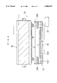
- FIG. 2 is a front sectional view taken along a line A--A of FIG. 1;
- FIG. 3 is a view showing the path of a web in a coating system including the first embodiment of the web charging apparatus according to the present invention
- FIG. 4 is a side view of assistance in explaining the second embodiment of the web charging apparatus according to the present invention.
- FIG. 5 is a side view of assistance in explaining the third embodiment of the web charging apparatus according to the present invention.
- FIG. 6 is a front sectional view illustrating the fourth embodiment of the web charging apparatus according to the present invention.
- FIG. 7 is a front sectional view illustrating the fifth embodiment of the web charging apparatus according to the present invention.
- FIG. 1 is a side view of assistance in explaining the first embodiment of a web charging apparatus according to the present invention.
- FIG. 2 is a front sectional view taken along the line A--A of FIG. 1.
- the web charging apparatus 10 comprises a discharge electrode device 12 and a first grounded electrode or a roller 16 that is grounded and provided above the discharge electrode device 12.
- the roller 16 serves both as a counter electrode for corona discharge and a supporting roller for a moving web 14.
- the discharge electrode device 12 includes discharge electrodes or wire electrodes 18, which are supported in tension between side plates 20A of an electrode supporting frame 20 and are parallel to the axis of the roller 16A plurality of (e.g. four) wire electrodes 18 are arranged in parallel to each other at regular intervals on a circle concentric with the roller 16, in other words, the wire electrodes 18 are arranged along the path of the web 14.
- the wire electrodes 18 are made from a conductive material, e.g. tungsten, molybdenum, platinum, and carbon fiber, and preferably have a diameter of about 100 ⁇ m to about 200 ⁇ m.
- Each side plate 20A of the electrode supporting frame 20 is provided with stretchers (not shown), each of which supports an end of one of the wire electrodes 18 and can adjust a tensile force of the wire electrode 18.
- the wire electrodes 18 are preferably stretched under a tensile force of about 10N.
- each side plate 20A has a curve along the periphery of the roller 16.
- the web 14 moves over the roller 16 while being in contact with the outer surface of the roller 16, which is grounded to function as the counter electrode.
- the distance between each wire electrode 18 and the web 14 supported on the roller 16 is about 10 mm.
- the wire electrodes 18 are connected to a source 22 of direct voltage of about 6500V, and the corona discharge is established between the wire electrodes 18 and the roller 16 via the web 14.
- a second grounded electrode or a grounded plate 24 is arranged behind the wire electrodes 18 relative to the roller 16.
- the grounded plate 24 is grounded and is a rectangle whose length is substantially equal to the length of the wire electrodes 18 and whose width is substantially equal to the diameter of the roller 16.
- both lengthwise (widthwise of the web 14) end parts of the grounded plate 24, that is, the parts facing to the edge parts of the web 14 supported on the roller 16 are bent to be closer to the web 14.
- the grounded plate 24 is made from a metal, e.g. aluminum, copper, iron, and stainless steal, or a nonmetallic conductor.
- the web 14 passes through the web charging apparatus 10, and then, it reaches a coating apparatus 26.
- the source 22 applies a high voltage to the wire electrodes 18 so that the corona discharge is established between the wire electrodes 18 and the roller 16 via the web 14.
- unipolar electrostatic charges are deposited on the surface of the web 14.
- the web 14 passes a surface electrometer 28, which measures and records a surface electrostatic potential on the web 14, and reaches the coating apparatus 26 via a pass roller 30.
- a coating head 34 of the coating apparatus 26 applies a coating solution 36 to the surface of the web 14 supported on a backup roller 32.
- the web 14 is coated with the coating solution 36.
- the web charging apparatus 10 deposits the unipolar electrostatic charges on the surface of the web 14, thereby improving the affinity and adhesion of the coating solution 36 to the web 14.
- the coating performance can be improved.
- a conventional web charging apparatus has the problem of the "liquid exhaustion at the edge parts of the web" in that the edge parts of the web cannot satisfactorily be coated with the coating solution, since the electrostatic potential at the edge parts of the web is lower than the electrostatic potential at the central part of the web.
- the web charging apparatus 10 is provided with the grounded plate 24 behind the wire electrodes 18 relative to the roller 16.
- the grounded plate 24 By bending the lengthwise ends of the grounded plate 24 toward the web 14, it is easy to equalize the electrostatic potential at the edge parts and the central part of the web 14. Even if they are not bent, a satisfactory effect can also be achieved.
- the grounded plate 24 is provided behind the wire electrodes 18 relative to the roller 16, thereby equalizing the electrostatic potential at the edge parts and the central part of the web 14. That is because the intensity of the electrostatic field that is formed in the space between the wire electrodes 18 and the roller 16, is uniform over the whole width of the web 14. Thus, it is possible to prevent the "liquid exhaustion at the edge parts of the web" by providing the grounded plate 24.
- the web charging apparatus 10 there is no necessity to finely adjust the distance between each wire electrode 18 and the web 14 by less than 1 mm, unlike the conventional web charging apparatus. It is also possible to prevent the sag of the wire electrodes 18 from affecting the electrostatic potential on the web 14, thereby equalizing the electrostatic potential at the edge parts and the central part of the web 14.
- FIG. 4 is a side view of assistance in explaining the second embodiment of the web charging apparatus 10 according to the present invention, and parts similar to those of the first embodiment will be denoted by the same reference numerals.
- the grounded plate 24 is curved along the periphery of the roller 16. Thereby, the distances between the grounded plate 24 and the wire electrodes 18, which are arranged in parallel at regular intervals along the path of the web 14, can be uniform.
- the intensity of the electrostatic field that is formed between the wire electrodes 18 and the web 14 can also be uniform in the direction in which the web 14 moves. Thus, it is possible to avoid a change in the electrostatic potential in the direction in which the web 14 moves, so that the web 14 can be uniformly coated in its moving direction.
- FIG. 5 is a side view of assistance in explaining the third embodiment of the web charging apparatus 10 according to the present invention, and parts similar to those of the first embodiment will be denoted by the same reference numerals.
- the central part of the grounded plate 24 is curved along the periphery of the roller 16, and both widthwise end parts of the grounded plate 24 are bent toward the roller 16 in a manner to enclose the wire electrodes 18.
- the third embodiment can achieve the same effects as the second embodiment, and besides, the wire electrodes 18 are enclosed by the grounded plate 24 to prevent the disturbance. Thus, the electrostatic field can be more stable.
- FIG. 6 is a front sectional view of assistance in explaining the fourth embodiment of the web charging apparatus 10 according to the present invention, and parts similar to those of the first embodiment will be denoted by the same reference numerals.
- the grounded plate 24 is separated into three grounded plates 24A and 24B.
- the grounded plate 24A is arranged to face the central part of the web 14, and the grounded plates 24B are arranged to face both edge parts of the web 14.
- Each of the grounded plates 24A and 24B is movable in the vertical direction in FIG. 6.
- the grounded plate 24 there is no necessity to bend both lengthwise ends of the grounded plate 24. Moreover, it is possible to adjust the distances between the web 14 and the grounded plates 24B and between the web 14 and the grounded plate 24A independently of one another. Thus, it is possible to equalize the electrostatic potential at the edge parts and the central part of the web 14, or to intentionally make the electrostatic potential at the edge parts of the web 14 lower than the electrostatic potential at the central part of the web 14 to thereby decrease the coating solution applied on the edge parts of the web 14.
- the grounded plate 24A facing the central part of the web 14 may be removed, so that the only grounded plates 24B are arranged to face the edge parts of the web 14.
- FIG. 7 is a front sectional view of assistance in explaining the fifth embodiment of the web charging apparatus 10 according to the present invention, and parts similar to those of the first embodiment will be denoted by the same reference numerals.
- the grounded plate 24 is provided with a distance adjusting device or bolts 40 that adjust the distance between the grounded plate 24 and the wire electrodes 18.
- the ends of the bolts 40 which engage with a bottom plate of the electrode support frame 20, are in contact with the central part and the lengthwise end parts of the grounded plate 24.
- a material that elastically deforms easily is suitable for the grounded plate 24.
- the bolts 40 are pressed against the grounded plate 24, so that the distance between the grounded plate 24 and the web 14 can be finely adjusted so as to equalize the electrostatic potential at the edge parts and the central part of the web 14.
- the distance adjusting device for the grounded plate 24 are not restricted to the bolts 40, but air cylinders, etc. may be used.
- the number of the bolts 40 is not restricted to three.
- the first grounded electrode 16 functions as the supporting roller for the web 14, but the present invention should not be restricted to this.
- the first grounded electrode 16 may be an unrotative cylinder, a rod, a pipe, a plate, or a moving belt.
- the discharge electrode 18 should not be restricted to the wire, but may be a bristle brush.
- the number of the discharge electrodes 18 may be one.
- the second grounded electrode 24 should not be necessarily the rectangular plate.
- the second grounded electrode 24 may be any shape that does not disturb the electrostatic field between the wire electrodes 18 and the web 14.
- the second grounded electrode 24 may be a plane as in the first embodiment and an arc as in the second embodiment.
- the second grounded electrode 24 may be a wire, a rod, a belt, or a grid.
- a web as the web 14 was made of TAC (triacetyl cellulose), coated with gelatin, 200 mm in width, and ordinarily used for a photographic film.
- the web 14 was transported at a speed of 100 m/min.
- four wires as the wire electrodes 18 were made of tungsten, 100 ⁇ m in diameter, and 200 mm in length.
- the wire electrodes 18 were arranged in parallel so that each distance to the web 14 was 10 mm.
- An aluminum plate was used as the grounded plate 24.
- the power supply 22 applied a direct voltage of 6300 V to the wire electrodes 18, so that the corona discharge was established between the wire electrodes 18 and the web 14. Thereby, the unipolar electrostatic charges were deposited on the surface of the web 14. Then, the surface electrometer 28 measured the electrostatic potential on the charged surface of the web 14. After the measurement, the coating apparatus 26 applied the coating solution 36 on the web 14.
- the surface electrostatic potential on the web 14 was measured at the central part and the edge part, specifically, the point positioned inside by 20 mm from the widthwise end of the web 14.
- the measurement was also performed in the case where no grounded plate was provided.
- the measurement result was represented with surface electrostatic potential ratio defined as follows: ##EQU1##
- the surface electrostatic potential ratio was approximately 1 when the grounded plate 24 was provided, whereas the ratio was 0.42 when the grounded plate 24 was not provided. There may be some fluctuations in the ratios according to conditions such as the shape of the grounded plate 24 and the voltage applied to the wire electrodes 18.
- the surface electrostatic potential ratio was 1, and the electrostatic potential at the edge parts and the central part of the web 14 was perfectly uniform. Thus, it was proved that it is possible to uniformly deposit the unipolar electrostatic charges on the whole width of the web 14 by providing the grounded plate 24.
- the only grounded plates 24B of 20 mm in length were provided to face both edge parts of the web 14, and the other conditions were the same as in the first experiment.
- the distance between each wire electrode 18 and each grounded plate 24B was changed to 24 mm, 21 mm and 18 mm.
- the surface electrostatic potential on the web 14 was measured at the central part and the edge part thereof.
- the unipolar electrostatic charges can be uniformly deposited on the whole width of the web, and thus, it is possible to equalize the affinity and adhesion of the coating solution applied on the edge parts and the central part of the web.
- the coating apparatus utilizing the web charging apparatus according to the present invention can intentionally coat the edge parts of the web thicker than the central part.
Abstract
Description
              TABLE 1
______________________________________
Distance between wire electrodes and
  grounded plate [mm] Surface electrostatic potential ratio
______________________________________
24                0.78
  21 0.85
  18 0.94
  14 1.00
  No grounded plate was provided 0.42
______________________________________
              TABLE 2
______________________________________
Distance between wire electrodes and
  grounded plates [mm] Surface electrostatic potential ratio
______________________________________
24                1.23
  21 1.27
  18 1.50
  No grounded plate was provided 0.42
______________________________________
              TABLE 3
______________________________________
Distance between wire electrodes and
                  Liquid exhaustion
  grounded plate [mm] at the edge parts of the web
______________________________________
24                Not arising
  21 Not arising
  18 Not arising
  14 Not arising
  No grounded plate was provided Arising
______________________________________
Claims (14)
Applications Claiming Priority (2)
| Application Number | Priority Date | Filing Date | Title |
|---|---|---|---|
| JP9-122621 | 1997-05-13 | ||
| JP12262197A JP3944889B2 (en) | 1997-05-13 | 1997-05-13 | Web charging equipment |
Publications (1)
| Publication Number | Publication Date |
|---|---|
| US6086675A true US6086675A (en) | 2000-07-11 |
Family
ID=14840503
Family Applications (1)
| Application Number | Title | Priority Date | Filing Date |
|---|---|---|---|
| US09/074,387 Expired - Fee Related US6086675A (en) | 1997-05-13 | 1998-05-08 | Web charging apparatus |
Country Status (5)
| Country | Link |
|---|---|
| US (1) | US6086675A (en) |
| EP (3) | EP1465305A3 (en) |
| JP (1) | JP3944889B2 (en) |
| AT (1) | ATE272261T1 (en) |
| DE (1) | DE69825210T2 (en) |
Cited By (6)
| Publication number | Priority date | Publication date | Assignee | Title |
|---|---|---|---|---|
| US6436191B1 (en) * | 1997-12-01 | 2002-08-20 | Eastman Kodak Company | Corona discharge treatment roller and surface finishing process |
| US20060176641A1 (en) * | 2003-06-11 | 2006-08-10 | Peter Gefter | Ionizing electrode structure and apparatus |
| US7339778B1 (en) * | 2003-06-11 | 2008-03-04 | Ion Systems | Corona discharge static neutralizing apparatus |
| US20130032088A1 (en) * | 2009-12-15 | 2013-02-07 | Herbert Schulze | Method and device for the electrostatic separation of overspray |
| US20160279667A1 (en) * | 2015-03-26 | 2016-09-29 | Fuji Xerox Co., Ltd. | Powder coating apparatus |
| CN110039756A (en) * | 2019-03-26 | 2019-07-23 | 宁波太古新材料科技有限公司 | A kind of intelligent protection film corona treatment plant |
Citations (12)
| Publication number | Priority date | Publication date | Assignee | Title |
|---|---|---|---|---|
| US3390266A (en) * | 1964-11-05 | 1968-06-25 | Epping Reinhold Hermann | Apparatus for charging the surface of photoelectric layers using corona discharge |
| FR2073907A5 (en) * | 1969-12-17 | 1971-10-01 | Kalle Ag | |
| US3612864A (en) * | 1968-01-13 | 1971-10-12 | Yasuo Tamai | Imaging system utilizing an electrode treated with a mixture of a hygroscopic material and a hydrophilic binder |
| US3783283A (en) * | 1972-09-26 | 1974-01-01 | Sperry Rand Corp | Corona charging device with semiconductive shield |
| US3937960A (en) * | 1972-02-22 | 1976-02-10 | Rank Xerox, Ltd. | Charging device for electrophotography |
| US4322156A (en) * | 1979-08-14 | 1982-03-30 | Tokyo Shibaura Denki Kabushiki Kaisha | Charging apparatus for copying machine |
| US4326794A (en) * | 1979-10-31 | 1982-04-27 | Tokyo Shibaura Denki Kabushiki Kaisha | Electrostatic copying apparatus |
| US4486808A (en) * | 1982-12-03 | 1984-12-04 | Polaroid Corporation | Apparatus for controlling random charges on a moving web |
| US5018045A (en) * | 1989-04-14 | 1991-05-21 | Minolta Camera Kabushiki Kaisha | Corona discharger for use in electrophotographic copying machine |
| JPH0465088A (en) * | 1990-07-03 | 1992-03-02 | Fuji Photo Film Co Ltd | Web electrifying device |
| US5367366A (en) * | 1992-06-04 | 1994-11-22 | Sharp Kabushiki Kaisha | Corona charger for image forming apparatus providing uniform surface charge of a recording medium |
| US5373351A (en) * | 1991-07-22 | 1994-12-13 | Hitachi, Ltd. | Electrostatic recording apparatus and managing system thereof |
-
1997
- 1997-05-13 JP JP12262197A patent/JP3944889B2/en not_active Expired - Fee Related
-
1998
- 1998-05-08 US US09/074,387 patent/US6086675A/en not_active Expired - Fee Related
- 1998-05-11 AT AT98108556T patent/ATE272261T1/en not_active IP Right Cessation
- 1998-05-11 EP EP04017013A patent/EP1465305A3/en not_active Withdrawn
- 1998-05-11 DE DE1998625210 patent/DE69825210T2/en not_active Expired - Lifetime
- 1998-05-11 EP EP98108556A patent/EP0878885B1/en not_active Expired - Lifetime
- 1998-05-11 EP EP04017014A patent/EP1465306A3/en not_active Withdrawn
Patent Citations (13)
| Publication number | Priority date | Publication date | Assignee | Title |
|---|---|---|---|---|
| US3390266A (en) * | 1964-11-05 | 1968-06-25 | Epping Reinhold Hermann | Apparatus for charging the surface of photoelectric layers using corona discharge |
| US3612864A (en) * | 1968-01-13 | 1971-10-12 | Yasuo Tamai | Imaging system utilizing an electrode treated with a mixture of a hygroscopic material and a hydrophilic binder |
| FR2073907A5 (en) * | 1969-12-17 | 1971-10-01 | Kalle Ag | |
| US3937960A (en) * | 1972-02-22 | 1976-02-10 | Rank Xerox, Ltd. | Charging device for electrophotography |
| US3783283A (en) * | 1972-09-26 | 1974-01-01 | Sperry Rand Corp | Corona charging device with semiconductive shield |
| US4322156A (en) * | 1979-08-14 | 1982-03-30 | Tokyo Shibaura Denki Kabushiki Kaisha | Charging apparatus for copying machine |
| US4326794A (en) * | 1979-10-31 | 1982-04-27 | Tokyo Shibaura Denki Kabushiki Kaisha | Electrostatic copying apparatus |
| US4486808A (en) * | 1982-12-03 | 1984-12-04 | Polaroid Corporation | Apparatus for controlling random charges on a moving web |
| US5018045A (en) * | 1989-04-14 | 1991-05-21 | Minolta Camera Kabushiki Kaisha | Corona discharger for use in electrophotographic copying machine |
| JPH0465088A (en) * | 1990-07-03 | 1992-03-02 | Fuji Photo Film Co Ltd | Web electrifying device |
| US5138971A (en) * | 1990-07-03 | 1992-08-18 | Fuji Photo Film Co., Ltd. | Web charging apparatus |
| US5373351A (en) * | 1991-07-22 | 1994-12-13 | Hitachi, Ltd. | Electrostatic recording apparatus and managing system thereof |
| US5367366A (en) * | 1992-06-04 | 1994-11-22 | Sharp Kabushiki Kaisha | Corona charger for image forming apparatus providing uniform surface charge of a recording medium |
Cited By (11)
| Publication number | Priority date | Publication date | Assignee | Title |
|---|---|---|---|---|
| US6436191B1 (en) * | 1997-12-01 | 2002-08-20 | Eastman Kodak Company | Corona discharge treatment roller and surface finishing process |
| US20060176641A1 (en) * | 2003-06-11 | 2006-08-10 | Peter Gefter | Ionizing electrode structure and apparatus |
| US7339778B1 (en) * | 2003-06-11 | 2008-03-04 | Ion Systems | Corona discharge static neutralizing apparatus |
| US7483255B2 (en) | 2003-06-11 | 2009-01-27 | Ion Systems | Ionizing electrode structure and apparatus |
| US20130032088A1 (en) * | 2009-12-15 | 2013-02-07 | Herbert Schulze | Method and device for the electrostatic separation of overspray |
| US9073079B2 (en) * | 2009-12-15 | 2015-07-07 | Eisenmann Ag | Method and device for the electrostatic separation of overspray |
| US20160279667A1 (en) * | 2015-03-26 | 2016-09-29 | Fuji Xerox Co., Ltd. | Powder coating apparatus |
| CN106000805A (en) * | 2015-03-26 | 2016-10-12 | 富士施乐株式会社 | Powder coating apparatus |
| US9977383B2 (en) * | 2015-03-26 | 2018-05-22 | Fuji Xerox Co., Ltd. | Powder coating apparatus |
| CN106000805B (en) * | 2015-03-26 | 2018-11-27 | 富士施乐株式会社 | Powder coating apparatus |
| CN110039756A (en) * | 2019-03-26 | 2019-07-23 | 宁波太古新材料科技有限公司 | A kind of intelligent protection film corona treatment plant |
Also Published As
| Publication number | Publication date |
|---|---|
| EP0878885A1 (en) | 1998-11-18 |
| DE69825210D1 (en) | 2004-09-02 |
| JP3944889B2 (en) | 2007-07-18 |
| DE69825210T2 (en) | 2004-11-18 |
| EP1465306A3 (en) | 2005-03-30 |
| EP0878885B1 (en) | 2004-07-28 |
| ATE272261T1 (en) | 2004-08-15 |
| EP1465305A3 (en) | 2005-03-30 |
| EP1465306A2 (en) | 2004-10-06 |
| JPH10312878A (en) | 1998-11-24 |
| EP1465305A2 (en) | 2004-10-06 |
Similar Documents
| Publication | Publication Date | Title |
|---|---|---|
| US5138971A (en) | Web charging apparatus | |
| US6086675A (en) | Web charging apparatus | |
| US4513683A (en) | Coating uniformity improvement apparatus | |
| EP0386796B1 (en) | Method of applying single polar electrostatic charges to continously travelling long web support, and apparatus practicing same | |
| US6146805A (en) | Printing method, printer, printed object, and optical disk | |
| US5003325A (en) | Electric field paper stabilizing system for an electrographic plotter, printer or the like | |
| JPH069670B2 (en) | Application method | |
| US4112298A (en) | Corona wire mounting means | |
| US3976880A (en) | Corona stabilization arrangement | |
| CN220382162U (en) | Roller passing mechanism, smoothing device, battery winding equipment and battery production system | |
| JPS6057875A (en) | Developing apparatus for liquid development of electrostatic image on image support | |
| JP3255311B2 (en) | Recording electrode | |
| JPH01288879A (en) | Transfer roll mechanism | |
| US5138349A (en) | Apparatus for reducing the effects of ambient humidity variations upon an ionographic printing device | |
| JPH03106669A (en) | Ion flow recording head assembly | |
| SU413527A1 (en) | ||
| JP3292413B2 (en) | Image forming device | |
| JP2833098B2 (en) | Electrostatic recording head | |
| JPH03230969A (en) | Electrostatic recorder | |
| JPH09240036A (en) | Image forming apparatus | |
| JPH01257873A (en) | Alternating corona discharging device | |
| JPS601627A (en) | Manufacture of magnetic recording medium | |
| JP2003182133A (en) | Imaging apparatus | |
| JPH0789119A (en) | Image forming apparatus | |
| JPS59143167A (en) | Copying corona discharger |
Legal Events
| Date | Code | Title | Description |
|---|---|---|---|
| AS | Assignment |
Owner name: FUJI PHOTO FILM CO., LTD., JAPAN Free format text: ASSIGNMENT OF ASSIGNORS INTEREST;ASSIGNORS:HAMAMOTO, NOBUO;KOJIMA, KENJI;REEL/FRAME:009162/0204 Effective date: 19980428 |
|
| FEPP | Fee payment procedure |
Free format text: PAYOR NUMBER ASSIGNED (ORIGINAL EVENT CODE: ASPN); ENTITY STATUS OF PATENT OWNER: LARGE ENTITY |
|
| FPAY | Fee payment |
Year of fee payment: 4 |
|
| AS | Assignment |
Owner name: FUJIFILM CORPORATION, JAPAN Free format text: ASSIGNMENT OF ASSIGNORS INTEREST;ASSIGNOR:FUJIFILM HOLDINGS CORPORATION (FORMERLY FUJI PHOTO FILM CO., LTD.);REEL/FRAME:018904/0001 Effective date: 20070130 Owner name: FUJIFILM CORPORATION,JAPAN Free format text: ASSIGNMENT OF ASSIGNORS INTEREST;ASSIGNOR:FUJIFILM HOLDINGS CORPORATION (FORMERLY FUJI PHOTO FILM CO., LTD.);REEL/FRAME:018904/0001 Effective date: 20070130 |
|
| FPAY | Fee payment |
Year of fee payment: 8 |
|
| REMI | Maintenance fee reminder mailed | ||
| LAPS | Lapse for failure to pay maintenance fees | ||
| STCH | Information on status: patent discontinuation |
Free format text: PATENT EXPIRED DUE TO NONPAYMENT OF MAINTENANCE FEES UNDER 37 CFR 1.362 |
|
| FP | Lapsed due to failure to pay maintenance fee |
Effective date: 20120711 |