US6090233A - Irrigation hose splice and method of making same - Google Patents
Irrigation hose splice and method of making same Download PDFInfo
- Publication number
- US6090233A US6090233A US09/071,524 US7152498A US6090233A US 6090233 A US6090233 A US 6090233A US 7152498 A US7152498 A US 7152498A US 6090233 A US6090233 A US 6090233A
- Authority
- US
- United States
- Prior art keywords
- hose
- segment
- irrigation
- repaired
- heat
- Prior art date
- Legal status (The legal status is an assumption and is not a legal conclusion. Google has not performed a legal analysis and makes no representation as to the accuracy of the status listed.)
- Expired - Fee Related
Links
Images

Classifications
-
- F—MECHANICAL ENGINEERING; LIGHTING; HEATING; WEAPONS; BLASTING
- F16—ENGINEERING ELEMENTS AND UNITS; GENERAL MEASURES FOR PRODUCING AND MAINTAINING EFFECTIVE FUNCTIONING OF MACHINES OR INSTALLATIONS; THERMAL INSULATION IN GENERAL
- F16L—PIPES; JOINTS OR FITTINGS FOR PIPES; SUPPORTS FOR PIPES, CABLES OR PROTECTIVE TUBING; MEANS FOR THERMAL INSULATION IN GENERAL
- F16L47/00—Connecting arrangements or other fittings specially adapted to be made of plastics or to be used with pipes made of plastics
- F16L47/02—Welded joints; Adhesive joints
-
- B—PERFORMING OPERATIONS; TRANSPORTING
- B29—WORKING OF PLASTICS; WORKING OF SUBSTANCES IN A PLASTIC STATE IN GENERAL
- B29C—SHAPING OR JOINING OF PLASTICS; SHAPING OF MATERIAL IN A PLASTIC STATE, NOT OTHERWISE PROVIDED FOR; AFTER-TREATMENT OF THE SHAPED PRODUCTS, e.g. REPAIRING
- B29C65/00—Joining or sealing of preformed parts, e.g. welding of plastics materials; Apparatus therefor
- B29C65/02—Joining or sealing of preformed parts, e.g. welding of plastics materials; Apparatus therefor by heating, with or without pressure
- B29C65/18—Joining or sealing of preformed parts, e.g. welding of plastics materials; Apparatus therefor by heating, with or without pressure using heated tools
- B29C65/22—Heated wire resistive ribbon, resistive band or resistive strip
-
- B—PERFORMING OPERATIONS; TRANSPORTING
- B29—WORKING OF PLASTICS; WORKING OF SUBSTANCES IN A PLASTIC STATE IN GENERAL
- B29C—SHAPING OR JOINING OF PLASTICS; SHAPING OF MATERIAL IN A PLASTIC STATE, NOT OTHERWISE PROVIDED FOR; AFTER-TREATMENT OF THE SHAPED PRODUCTS, e.g. REPAIRING
- B29C65/00—Joining or sealing of preformed parts, e.g. welding of plastics materials; Apparatus therefor
- B29C65/02—Joining or sealing of preformed parts, e.g. welding of plastics materials; Apparatus therefor by heating, with or without pressure
- B29C65/38—Impulse heating
-
- B—PERFORMING OPERATIONS; TRANSPORTING
- B29—WORKING OF PLASTICS; WORKING OF SUBSTANCES IN A PLASTIC STATE IN GENERAL
- B29C—SHAPING OR JOINING OF PLASTICS; SHAPING OF MATERIAL IN A PLASTIC STATE, NOT OTHERWISE PROVIDED FOR; AFTER-TREATMENT OF THE SHAPED PRODUCTS, e.g. REPAIRING
- B29C66/00—General aspects of processes or apparatus for joining preformed parts
- B29C66/004—Preventing sticking together, e.g. of some areas of the parts to be joined
-
- B—PERFORMING OPERATIONS; TRANSPORTING
- B29—WORKING OF PLASTICS; WORKING OF SUBSTANCES IN A PLASTIC STATE IN GENERAL
- B29C—SHAPING OR JOINING OF PLASTICS; SHAPING OF MATERIAL IN A PLASTIC STATE, NOT OTHERWISE PROVIDED FOR; AFTER-TREATMENT OF THE SHAPED PRODUCTS, e.g. REPAIRING
- B29C66/00—General aspects of processes or apparatus for joining preformed parts
- B29C66/01—General aspects dealing with the joint area or with the area to be joined
- B29C66/05—Particular design of joint configurations
- B29C66/10—Particular design of joint configurations particular design of the joint cross-sections
- B29C66/11—Joint cross-sections comprising a single joint-segment, i.e. one of the parts to be joined comprising a single joint-segment in the joint cross-section
- B29C66/112—Single lapped joints
- B29C66/1122—Single lap to lap joints, i.e. overlap joints
-
- B—PERFORMING OPERATIONS; TRANSPORTING
- B29—WORKING OF PLASTICS; WORKING OF SUBSTANCES IN A PLASTIC STATE IN GENERAL
- B29C—SHAPING OR JOINING OF PLASTICS; SHAPING OF MATERIAL IN A PLASTIC STATE, NOT OTHERWISE PROVIDED FOR; AFTER-TREATMENT OF THE SHAPED PRODUCTS, e.g. REPAIRING
- B29C66/00—General aspects of processes or apparatus for joining preformed parts
- B29C66/50—General aspects of joining tubular articles; General aspects of joining long products, i.e. bars or profiled elements; General aspects of joining single elements to tubular articles, hollow articles or bars; General aspects of joining several hollow-preforms to form hollow or tubular articles
- B29C66/51—Joining tubular articles, profiled elements or bars; Joining single elements to tubular articles, hollow articles or bars; Joining several hollow-preforms to form hollow or tubular articles
- B29C66/52—Joining tubular articles, bars or profiled elements
- B29C66/522—Joining tubular articles
- B29C66/5221—Joining tubular articles for forming coaxial connections, i.e. the tubular articles to be joined forming a zero angle relative to each other
-
- B—PERFORMING OPERATIONS; TRANSPORTING
- B29—WORKING OF PLASTICS; WORKING OF SUBSTANCES IN A PLASTIC STATE IN GENERAL
- B29C—SHAPING OR JOINING OF PLASTICS; SHAPING OF MATERIAL IN A PLASTIC STATE, NOT OTHERWISE PROVIDED FOR; AFTER-TREATMENT OF THE SHAPED PRODUCTS, e.g. REPAIRING
- B29C66/00—General aspects of processes or apparatus for joining preformed parts
- B29C66/80—General aspects of machine operations or constructions and parts thereof
- B29C66/83—General aspects of machine operations or constructions and parts thereof characterised by the movement of the joining or pressing tools
- B29C66/832—Reciprocating joining or pressing tools
- B29C66/8322—Joining or pressing tools reciprocating along one axis
- B29C66/83221—Joining or pressing tools reciprocating along one axis cooperating reciprocating tools, each tool reciprocating along one axis
-
- B—PERFORMING OPERATIONS; TRANSPORTING
- B29—WORKING OF PLASTICS; WORKING OF SUBSTANCES IN A PLASTIC STATE IN GENERAL
- B29C—SHAPING OR JOINING OF PLASTICS; SHAPING OF MATERIAL IN A PLASTIC STATE, NOT OTHERWISE PROVIDED FOR; AFTER-TREATMENT OF THE SHAPED PRODUCTS, e.g. REPAIRING
- B29C66/00—General aspects of processes or apparatus for joining preformed parts
- B29C66/90—Measuring or controlling the joining process
- B29C66/91—Measuring or controlling the joining process by measuring or controlling the temperature, the heat or the thermal flux
- B29C66/914—Measuring or controlling the joining process by measuring or controlling the temperature, the heat or the thermal flux by controlling or regulating the temperature, the heat or the thermal flux
- B29C66/9161—Measuring or controlling the joining process by measuring or controlling the temperature, the heat or the thermal flux by controlling or regulating the temperature, the heat or the thermal flux by controlling or regulating the heat or the thermal flux, i.e. the heat flux
- B29C66/91651—Measuring or controlling the joining process by measuring or controlling the temperature, the heat or the thermal flux by controlling or regulating the temperature, the heat or the thermal flux by controlling or regulating the heat or the thermal flux, i.e. the heat flux by controlling or regulating the heat generated by Joule heating or induction heating
- B29C66/91655—Measuring or controlling the joining process by measuring or controlling the temperature, the heat or the thermal flux by controlling or regulating the temperature, the heat or the thermal flux by controlling or regulating the heat or the thermal flux, i.e. the heat flux by controlling or regulating the heat generated by Joule heating or induction heating by controlling or regulating the current intensity
-
- B—PERFORMING OPERATIONS; TRANSPORTING
- B29—WORKING OF PLASTICS; WORKING OF SUBSTANCES IN A PLASTIC STATE IN GENERAL
- B29C—SHAPING OR JOINING OF PLASTICS; SHAPING OF MATERIAL IN A PLASTIC STATE, NOT OTHERWISE PROVIDED FOR; AFTER-TREATMENT OF THE SHAPED PRODUCTS, e.g. REPAIRING
- B29C65/00—Joining or sealing of preformed parts, e.g. welding of plastics materials; Apparatus therefor
- B29C65/02—Joining or sealing of preformed parts, e.g. welding of plastics materials; Apparatus therefor by heating, with or without pressure
- B29C65/08—Joining or sealing of preformed parts, e.g. welding of plastics materials; Apparatus therefor by heating, with or without pressure using ultrasonic vibrations
-
- B—PERFORMING OPERATIONS; TRANSPORTING
- B29—WORKING OF PLASTICS; WORKING OF SUBSTANCES IN A PLASTIC STATE IN GENERAL
- B29C—SHAPING OR JOINING OF PLASTICS; SHAPING OF MATERIAL IN A PLASTIC STATE, NOT OTHERWISE PROVIDED FOR; AFTER-TREATMENT OF THE SHAPED PRODUCTS, e.g. REPAIRING
- B29C66/00—General aspects of processes or apparatus for joining preformed parts
- B29C66/80—General aspects of machine operations or constructions and parts thereof
- B29C66/82—Pressure application arrangements, e.g. transmission or actuating mechanisms for joining tools or clamps
- B29C66/824—Actuating mechanisms
- B29C66/8242—Pneumatic or hydraulic drives
-
- B—PERFORMING OPERATIONS; TRANSPORTING
- B29—WORKING OF PLASTICS; WORKING OF SUBSTANCES IN A PLASTIC STATE IN GENERAL
- B29C—SHAPING OR JOINING OF PLASTICS; SHAPING OF MATERIAL IN A PLASTIC STATE, NOT OTHERWISE PROVIDED FOR; AFTER-TREATMENT OF THE SHAPED PRODUCTS, e.g. REPAIRING
- B29C66/00—General aspects of processes or apparatus for joining preformed parts
- B29C66/80—General aspects of machine operations or constructions and parts thereof
- B29C66/84—Specific machine types or machines suitable for specific applications
- B29C66/861—Hand-held tools
- B29C66/8614—Tongs, pincers or scissors
-
- B—PERFORMING OPERATIONS; TRANSPORTING
- B29—WORKING OF PLASTICS; WORKING OF SUBSTANCES IN A PLASTIC STATE IN GENERAL
- B29C—SHAPING OR JOINING OF PLASTICS; SHAPING OF MATERIAL IN A PLASTIC STATE, NOT OTHERWISE PROVIDED FOR; AFTER-TREATMENT OF THE SHAPED PRODUCTS, e.g. REPAIRING
- B29C66/00—General aspects of processes or apparatus for joining preformed parts
- B29C66/80—General aspects of machine operations or constructions and parts thereof
- B29C66/84—Specific machine types or machines suitable for specific applications
- B29C66/861—Hand-held tools
- B29C66/8618—Hand-held tools being battery operated
-
- B—PERFORMING OPERATIONS; TRANSPORTING
- B29—WORKING OF PLASTICS; WORKING OF SUBSTANCES IN A PLASTIC STATE IN GENERAL
- B29C—SHAPING OR JOINING OF PLASTICS; SHAPING OF MATERIAL IN A PLASTIC STATE, NOT OTHERWISE PROVIDED FOR; AFTER-TREATMENT OF THE SHAPED PRODUCTS, e.g. REPAIRING
- B29C66/00—General aspects of processes or apparatus for joining preformed parts
- B29C66/90—Measuring or controlling the joining process
- B29C66/92—Measuring or controlling the joining process by measuring or controlling the pressure, the force, the mechanical power or the displacement of the joining tools
- B29C66/929—Measuring or controlling the joining process by measuring or controlling the pressure, the force, the mechanical power or the displacement of the joining tools characterized by specific pressure, force, mechanical power or displacement values or ranges
-
- B—PERFORMING OPERATIONS; TRANSPORTING
- B29—WORKING OF PLASTICS; WORKING OF SUBSTANCES IN A PLASTIC STATE IN GENERAL
- B29L—INDEXING SCHEME ASSOCIATED WITH SUBCLASS B29C, RELATING TO PARTICULAR ARTICLES
- B29L2023/00—Tubular articles
- B29L2023/005—Hoses, i.e. flexible
-
- B—PERFORMING OPERATIONS; TRANSPORTING
- B29—WORKING OF PLASTICS; WORKING OF SUBSTANCES IN A PLASTIC STATE IN GENERAL
- B29L—INDEXING SCHEME ASSOCIATED WITH SUBCLASS B29C, RELATING TO PARTICULAR ARTICLES
- B29L2023/00—Tubular articles
- B29L2023/22—Tubes or pipes, i.e. rigid
-
- Y—GENERAL TAGGING OF NEW TECHNOLOGICAL DEVELOPMENTS; GENERAL TAGGING OF CROSS-SECTIONAL TECHNOLOGIES SPANNING OVER SEVERAL SECTIONS OF THE IPC; TECHNICAL SUBJECTS COVERED BY FORMER USPC CROSS-REFERENCE ART COLLECTIONS [XRACs] AND DIGESTS
- Y10—TECHNICAL SUBJECTS COVERED BY FORMER USPC
- Y10T—TECHNICAL SUBJECTS COVERED BY FORMER US CLASSIFICATION
- Y10T428/00—Stock material or miscellaneous articles
- Y10T428/13—Hollow or container type article [e.g., tube, vase, etc.]
- Y10T428/1352—Polymer or resin containing [i.e., natural or synthetic]
- Y10T428/139—Open-ended, self-supporting conduit, cylinder, or tube-type article
Definitions
- the present invention relates to agricultural irrigation, and more specifically, to an irrigation hose splice and method of making such a splice, including irrigation hose splices for irrigation hoses known as "drip tape" which are used to irrigate crops by distributing water substantially uniformly at discreet locations spaced along the length of the tape.
- irrigation hose splices for irrigation hoses known as "drip tape” which are used to irrigate crops by distributing water substantially uniformly at discreet locations spaced along the length of the tape.
- Drip tapes are more easily rolled, transported, and stored than are hoses which remain always round in cross section. Moreover, drip tape has become increasingly popular in row-crop farming because water is distributed to the soil immediately adjacent to the growing plants, and the entire field need not be irrigated. Strawberry growers, in particular, have almost uniformly adopted the use of drip tape.
- a major problem hindering the further use of drip tape for agricultural irrigation of major crops is the cost of replacing drip tape or repairing existing drip tape.
- most major crops have a value per acre that does not justify the continual replacement cost of new drip tape or the labor costs associated with the retrieval and reinstallation of used drip tape using conventional methods.
- One exception is strawberry growers who almost unanimously discard the old drip tape and replace it with new drip tape with each annual planting. Strawberries have a high cash value per acre, and therefore the cost of replacing drip tape is economically justifiable.
- drip tape In addition to the cost of replacing drip tape with each crop, discarded drip tape is environmentally unfriendly. For example, one acre of strawberries requires approximately 12,000 to 16,000 linear feet of drip tape depending on the row spacing. Because drip tape is replaced with each crop, which is every year for strawberries, landfills are increasingly becoming strewn with used drip tape.
- the present invention relates to an irrigation hose splice and method of making the same, including a hose splice for drip tape, requiring minimal time and equipment. Moreover, the present invention allows the repaired irrigation hose to be retrieved and re-installed in the same manner as new or undamaged hose. Finally, the present invention is environmentally friendly in that it reduces the amount of irrigation hose discarded with each crop.
- the method of making an irrigation hose splice includes inserting a first hose segment into a second hose segment so that the first hose segment is completely circumscribed by the second hose segment. This creates an overlapping area preferably less than one inch in length. The first and second hose segments are then fused together by externally applying heat and pressure at the overlapping area to create an irrigation hose splice. The irrigation hose splice is then cooled.
- An important feature of the present invention is the insertion of a heat shield into the first hose segment, i.e., the hose segment that is completely circumscribed by the second hose segment.
- the heat shield prevents the inner circumferential surface of the first segment from sealing onto itself which would restrict fluid flow within the irrigation hose. This results in a repaired irrigation hose that can withstand greater longitudinal forces, especially prevalent during installation and retrieval.
- the heat shield itself may contain a layer of hose material in addition to the heat resistant material.
- the heat shield may be water soluable such that the heat shield remaining in the irrigation hose can be removed by dissolving it with water during irrigation. Alternatively, the heat shield can be forced out by flushing the hose prior to use.
- FIG. 1 is an exploded view of the two hose segments to be repaired according to the the method of the present invention.
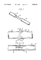
- FIG. 2 is a plan view of a splice joint of an irrigation hose of the present invention.
- FIG. 3 is a sectional view of the hose segment and heat shield of FIG. 1 as assembled prior to applying heat and pressure to the joint.
- FIG. 4 is a top view of the joint of FIG. 3.
- FIG. 5 is a sectional view of the joint of FIG. 3 during the application of heat and pressure.
- FIG. 6 is a sectional view of an alternative heat shield.
- FIG. 7 is a sectional view of the hose segment and the alternative heat shield prior to applying heat and pressure to the joint.
- the hose can be flexible such as a flexible polymer hose or a flexible co-polymer hose with wall thickness ranging from 0.004" to 0.112". Additionally, the flexible polymer hose can be mono-chambered or multi-chambered.
- multi-chambered hose known as drip tape is described in U.S. Pat. Nos. 5,620,143 issued Apr. 15, 1997; 5,695,127 issued Dec. 9, 1997; 4,473,191 issued Sept. 25, 1984; 4,247,051 issued Jan. 27, 1981; or 4,880,167 issued Nov. 14, 1989.
- An example of the thicker mono-chambered hose is one sold by the Toro Company under the designation OVAL HOSETM.
- a flat heat shield 16 is positioned within the inner segment 12 so that, preferably, it will be at least co-extensive with the overlapping area 18.
- the overlapping area 18 is less than one inch in linear length.
- the hose splice 20 extends transversely to the hose segements 12 and 14 and is composed of material from the inner segment 12 and the outer segment 14 that have been fused together by a heat sealer 22 which applies heat and compressive force as shown in FIG. 5.
- the fusion of the inner hose segment 12 and the other hose segment 14 creates tabs 19 extending radially beyond the circumference of the non-fused irrigation hose.
- the fusing also creates two discontinuties 21 extending circumferentially around the irrigation hose.
- a repaired irrigation hose splice 20 may be accomplished by first un-coiling two unjoined hose segments, the first segment 12 and the second segment 14, of the irrigation hose from a take-up spool (not shown). Next, the heat shield 16 is inserted into the first or inner segment of hose 12 to prevent the inner circumferential surface on the inner segment 12 from adhering to itself during heat fusion. The width of the heat shield may be preferably about half the circumference of the inner surface of the irrigation hose. The inner segment 12 is then partially inserted into the outer segment of hose 14 creating the overlapping area 18. The inner segment 12 is then heat fused to the outer segment 14.
- the heat fusion is accomplished by sandwiching the overlapping area 18 in a table top impulse heat sealer 22, or other suitable device such as are known in the art, which provides heat while simultaneously compressing the inner segment 12 and the outer segment 14 preferably at a point intermediate of the overlapping area 18 to form a hose splice 20.
- a table top impulse heat sealer 22 or other suitable device such as are known in the art, which provides heat while simultaneously compressing the inner segment 12 and the outer segment 14 preferably at a point intermediate of the overlapping area 18 to form a hose splice 20.
- One suitable heat sealer is sold by Bradley's Plastic Bag Co. under the designation 400TM.
- the irrigation hose segments 12 and 14 remain compressed while the heat is removed.
- the pressure is then removed resulting in a repaired irrigation hose 10.
- the repaired irrigation hose 10 may then be re-coiled onto a second take-up spool (not shown).
- the heat shield 16 is composed of water soluble material.
- examples include water soluble paper or starch based water soluble material.
- the heat shield 16 can be composed of any number of materials as long as the material prevents the inner circumferential surface from adhering to itself when the heat and compressive forces are applied.
- suitable materials include waxed paper, fiberglass, cotton, wool, asbestos, and Teflon R.
- a heat shield 24 is composed of two layers, one of which acts to prevent the inner circumferential surface from adhering to itself, the heat resistant material 26, and the other is composed of the same or similar material as the hose, the heat sensitive material 28.
- the heat shield 24 is applied in a similar fashion as described above in reference to FIGS. 1-5, except that the heat sensitive material 28 in the heat shield 24 fuses with the inner segment 12 when heat and pressure are applied by the heat sealer 22.
- This alternative embodiment of the heat shield 24 is especially desirable when using multi-chambered flexible hose which has circumferential portions that are mono-chambered (not shown) and circumferential portions that are multi-chambered (not shown).
- multi-chambered hose examples are described in U.S. Pat. Nos. 5,620,143 issued Apr. 15, 1997; 5,696,127 issued Dec. 9, 1997; 4,473,191 issued Sep. 25, 1984; 4,247,051 issued Jan. 27, 1981; and 4,880,167 issued Nov. 14, 1989.
- the heat sensitive material 28 in the heat shield 24 prevents the mono-chambered circumferential portions of the hose segments 12 and 14 from being damaged by the application of heat and pressure required to fuse together the thicker multi-chambered portions of the hose segments.
- the use of the multi-layered heat shield 24 also results in a repaired hose 10 that can withstand greater longitudinal forces, especially prevalent during installation and retrieval of the irrigation hose.
- the application of heat and compressive forces is automated in the heat sealer 22. That is, the heat sealer 22 would contain mechanical and electrical means that perform the sealing process with pre-programmed/pre-determined heat, heat time, cool down time, applied pressure, and duration of the pressure sequence.
- the heat can be preset in a number of ways including use of an adjustable rheostat control.
- the pressure can be controlled in a number of ways including using compressed air passing through a pressure regulator and solenoid valve which in turn activates an air piston which pushes the hose flat against the heater filament.
- pressure is applied for about 26 seconds at about 60 psi.
- the duration of heat application is about 12 seconds when repairing 10 mil Tiger TapeTM and is applied using an electronic timing device.
- all of the pre-programed/pre-determined settings can be adjusted to optimize quality of the hose splice 20 depending upon the thickness of the irrigation hose being repaired. For example pressure may be applied from 10 seconds for very thin hoses up to 3 minutes for thicker hoses. Likewise, pressure can be applied from 10 psi to 200 psi. Heat temperature will also vary with the thickness of the hose, but should preferably be greater than the melting point of the hose material.
- heat can be applied from 5 seconds to a minute and a half depending upon the thickness of the hose, the pressure, the temperature of the sealer and the width of the hose splice 20.
- a heat sealer 22 may be portable and battery operated so that it could be operated in the field to repair installed hose without having to retrieve the hose to repair it and later re-install it.
- a portable heat sealer may resemble a set of pliers (but with a battery operated heating element attached).
- the method of the present invention also contemplates alternative means of fusing other than using heat.
- the un-joined segments of hose can be fused together by ultrasonic welding.
- the present invention provides a method for easily repairing irrigation hose, including drip tape, with minimal time and equipment in a manner that allows the repaired irrigation hose to be retrieved and re-installed as though it were new or undamaged hose.
Abstract
Description
Claims (10)
Priority Applications (5)
| Application Number | Priority Date | Filing Date | Title |
|---|---|---|---|
| US09/071,524 US6090233A (en) | 1998-05-01 | 1998-05-01 | Irrigation hose splice and method of making same |
| AU37631/99A AU3763199A (en) | 1998-05-01 | 1999-04-27 | Irrigation hose splice and method of making same |
| EP99920047A EP1100678A4 (en) | 1998-05-01 | 1999-04-27 | Irrigation hose splice and method of making same |
| PCT/US1999/009051 WO1999056955A1 (en) | 1998-05-01 | 1999-04-27 | Irrigation hose splice and method of making same |
| US09/522,451 US6440510B1 (en) | 1998-05-01 | 2000-03-09 | Irrigation hose splice |
Applications Claiming Priority (1)
| Application Number | Priority Date | Filing Date | Title |
|---|---|---|---|
| US09/071,524 US6090233A (en) | 1998-05-01 | 1998-05-01 | Irrigation hose splice and method of making same |
Related Child Applications (1)
| Application Number | Title | Priority Date | Filing Date |
|---|---|---|---|
| US09/522,451 Division US6440510B1 (en) | 1998-05-01 | 2000-03-09 | Irrigation hose splice |
Publications (1)
| Publication Number | Publication Date |
|---|---|
| US6090233A true US6090233A (en) | 2000-07-18 |
Family
ID=22101886
Family Applications (2)
| Application Number | Title | Priority Date | Filing Date |
|---|---|---|---|
| US09/071,524 Expired - Fee Related US6090233A (en) | 1998-05-01 | 1998-05-01 | Irrigation hose splice and method of making same |
| US09/522,451 Expired - Fee Related US6440510B1 (en) | 1998-05-01 | 2000-03-09 | Irrigation hose splice |
Family Applications After (1)
| Application Number | Title | Priority Date | Filing Date |
|---|---|---|---|
| US09/522,451 Expired - Fee Related US6440510B1 (en) | 1998-05-01 | 2000-03-09 | Irrigation hose splice |
Country Status (4)
| Country | Link |
|---|---|
| US (2) | US6090233A (en) |
| EP (1) | EP1100678A4 (en) |
| AU (1) | AU3763199A (en) |
| WO (1) | WO1999056955A1 (en) |
Cited By (9)
| Publication number | Priority date | Publication date | Assignee | Title |
|---|---|---|---|---|
| US6540859B1 (en) | 2001-10-16 | 2003-04-01 | The Toro Company | Method for splicing hose |
| US6632306B1 (en) | 2000-08-07 | 2003-10-14 | Roberts Group Holdings, Llc | Method and apparatus for splicing drip irrigation tape |
| US20070265698A1 (en) * | 2003-07-31 | 2007-11-15 | Advanced Cardiovascular Systems, Inc. | Intravascular stent with inverted end rings |
| US20080009829A1 (en) * | 2006-07-07 | 2008-01-10 | Abbott Cardiovascular Systems Inc. | Balloon catheter having a branched distal section with secured branches |
| US20080174109A1 (en) * | 2007-01-23 | 2008-07-24 | Netafim Ltd. | Irrigation Pipe Splice Sleeve and Method |
| US20090012601A1 (en) * | 2007-07-05 | 2009-01-08 | Abbott Cardiovascular Systems, Inc. | Stent and catheter assembly and method for treating bifurcations |
| US20090051159A1 (en) * | 2007-08-20 | 2009-02-26 | Scott Glenn Cameron | Fluid fitting for an agricultural drip irrigation system |
| US8210573B2 (en) | 2001-07-12 | 2012-07-03 | Delmer Dan W C | Pipe coupling |
| DE102017106906A1 (en) * | 2017-03-30 | 2018-10-04 | Tpu Plus Gmbh | Method for welding |
Families Citing this family (3)
| Publication number | Priority date | Publication date | Assignee | Title |
|---|---|---|---|---|
| TWI255357B (en) * | 2003-05-13 | 2006-05-21 | Federal Mogul Powertrain Inc | Sleeve splicing kit and method |
| GB2562546B (en) * | 2017-07-07 | 2019-07-03 | Mjs Healthcare Ltd | Bladder |
| GB2590935A (en) * | 2020-01-07 | 2021-07-14 | Salts Healthcare Ltd | A method of manufacturing an ostomy appliance |
Citations (20)
| Publication number | Priority date | Publication date | Assignee | Title |
|---|---|---|---|---|
| US2503882A (en) * | 1946-02-05 | 1950-04-11 | Johnson Rubber Co | Method of joining hollow members |
| US3635504A (en) * | 1968-10-07 | 1972-01-18 | Goodall Rubber Co | Hose splice |
| US3666586A (en) * | 1970-11-10 | 1972-05-30 | Edward H Lacey | Cord reinforced hose splicing method |
| US3998682A (en) * | 1973-11-27 | 1976-12-21 | Wavin B.V. | Method and device for welding polyolefinic objects |
| US4032176A (en) * | 1975-09-05 | 1977-06-28 | Viscora | Method of assembling seamless flexible tubing and the tubular assembly of lengths of such tubing |
| US4092193A (en) * | 1975-06-30 | 1978-05-30 | Raychem Corporation | Method for joining substrates utilizing coupling means |
| US4204897A (en) * | 1978-07-25 | 1980-05-27 | The Goodyear Tire & Rubber Company | Method and apparatus for splicing hose |
| US4215516A (en) * | 1979-04-18 | 1980-08-05 | Sheldahl, Inc. | Unidirectional tape |
| EP0116019A1 (en) * | 1983-01-04 | 1984-08-15 | Fiab System Ab | A method of joining preferably tubular bodies end-to-end and an apparatus for performing the method |
| US4610742A (en) * | 1984-11-15 | 1986-09-09 | Teepak, Inc. | Methods and materials for splicing tubular food casings |
| US4630846A (en) * | 1983-04-07 | 1986-12-23 | Hitachi Zosen Corporation | Pipe joint |
| US4636272A (en) * | 1985-02-19 | 1987-01-13 | Cordis Corporation | Process for thermally bonding plastic tubes |
| US4736775A (en) * | 1986-12-24 | 1988-04-12 | Viskase Corporation | Food casing splice having dual pressure sensitive tapes |
| US4801349A (en) * | 1986-10-30 | 1989-01-31 | Armin Dommer | Apparatus for butt-welding plastic pipe sections or plastic fittings |
| US4906313A (en) * | 1988-05-09 | 1990-03-06 | R. W. Lyall & Company, Inc. | Fusion weld method and assembly for forming a fusion welded joint between pipe sections |
| US5141580A (en) * | 1989-11-29 | 1992-08-25 | Gaz De France | Connection component for together plastic elements by thermal welding |
| US5175032A (en) * | 1991-05-02 | 1992-12-29 | Shaw Industries Ltd. | Heat shrinkable closure sheets and sleeve structures and methods employing the same |
| US5592726A (en) * | 1995-01-06 | 1997-01-14 | The Deutsch Company | Axial swage tool having a stabilizing pin |
| US5634751A (en) * | 1994-02-25 | 1997-06-03 | Monogram Aerospace Fasteners | Blind fastener with deformable sleeve |
| US5690769A (en) * | 1995-08-21 | 1997-11-25 | T-Systems International | Method for splicing drip irrigation hoses using splicing means internal to the hoses |
-
1998
- 1998-05-01 US US09/071,524 patent/US6090233A/en not_active Expired - Fee Related
-
1999
- 1999-04-27 WO PCT/US1999/009051 patent/WO1999056955A1/en not_active Application Discontinuation
- 1999-04-27 EP EP99920047A patent/EP1100678A4/en not_active Withdrawn
- 1999-04-27 AU AU37631/99A patent/AU3763199A/en not_active Abandoned
-
2000
- 2000-03-09 US US09/522,451 patent/US6440510B1/en not_active Expired - Fee Related
Patent Citations (20)
| Publication number | Priority date | Publication date | Assignee | Title |
|---|---|---|---|---|
| US2503882A (en) * | 1946-02-05 | 1950-04-11 | Johnson Rubber Co | Method of joining hollow members |
| US3635504A (en) * | 1968-10-07 | 1972-01-18 | Goodall Rubber Co | Hose splice |
| US3666586A (en) * | 1970-11-10 | 1972-05-30 | Edward H Lacey | Cord reinforced hose splicing method |
| US3998682A (en) * | 1973-11-27 | 1976-12-21 | Wavin B.V. | Method and device for welding polyolefinic objects |
| US4092193A (en) * | 1975-06-30 | 1978-05-30 | Raychem Corporation | Method for joining substrates utilizing coupling means |
| US4032176A (en) * | 1975-09-05 | 1977-06-28 | Viscora | Method of assembling seamless flexible tubing and the tubular assembly of lengths of such tubing |
| US4204897A (en) * | 1978-07-25 | 1980-05-27 | The Goodyear Tire & Rubber Company | Method and apparatus for splicing hose |
| US4215516A (en) * | 1979-04-18 | 1980-08-05 | Sheldahl, Inc. | Unidirectional tape |
| EP0116019A1 (en) * | 1983-01-04 | 1984-08-15 | Fiab System Ab | A method of joining preferably tubular bodies end-to-end and an apparatus for performing the method |
| US4630846A (en) * | 1983-04-07 | 1986-12-23 | Hitachi Zosen Corporation | Pipe joint |
| US4610742A (en) * | 1984-11-15 | 1986-09-09 | Teepak, Inc. | Methods and materials for splicing tubular food casings |
| US4636272A (en) * | 1985-02-19 | 1987-01-13 | Cordis Corporation | Process for thermally bonding plastic tubes |
| US4801349A (en) * | 1986-10-30 | 1989-01-31 | Armin Dommer | Apparatus for butt-welding plastic pipe sections or plastic fittings |
| US4736775A (en) * | 1986-12-24 | 1988-04-12 | Viskase Corporation | Food casing splice having dual pressure sensitive tapes |
| US4906313A (en) * | 1988-05-09 | 1990-03-06 | R. W. Lyall & Company, Inc. | Fusion weld method and assembly for forming a fusion welded joint between pipe sections |
| US5141580A (en) * | 1989-11-29 | 1992-08-25 | Gaz De France | Connection component for together plastic elements by thermal welding |
| US5175032A (en) * | 1991-05-02 | 1992-12-29 | Shaw Industries Ltd. | Heat shrinkable closure sheets and sleeve structures and methods employing the same |
| US5634751A (en) * | 1994-02-25 | 1997-06-03 | Monogram Aerospace Fasteners | Blind fastener with deformable sleeve |
| US5592726A (en) * | 1995-01-06 | 1997-01-14 | The Deutsch Company | Axial swage tool having a stabilizing pin |
| US5690769A (en) * | 1995-08-21 | 1997-11-25 | T-Systems International | Method for splicing drip irrigation hoses using splicing means internal to the hoses |
Non-Patent Citations (2)
| Title |
|---|
| Disclosure, "Prior Art" --Hose Splice (Jul. 1999). |
| Disclosure, Prior Art Hose Splice (Jul. 1999). * |
Cited By (14)
| Publication number | Priority date | Publication date | Assignee | Title |
|---|---|---|---|---|
| US6632306B1 (en) | 2000-08-07 | 2003-10-14 | Roberts Group Holdings, Llc | Method and apparatus for splicing drip irrigation tape |
| US8210573B2 (en) | 2001-07-12 | 2012-07-03 | Delmer Dan W C | Pipe coupling |
| US6540859B1 (en) | 2001-10-16 | 2003-04-01 | The Toro Company | Method for splicing hose |
| US20070265698A1 (en) * | 2003-07-31 | 2007-11-15 | Advanced Cardiovascular Systems, Inc. | Intravascular stent with inverted end rings |
| US20080009829A1 (en) * | 2006-07-07 | 2008-01-10 | Abbott Cardiovascular Systems Inc. | Balloon catheter having a branched distal section with secured branches |
| US20080009932A1 (en) * | 2006-07-07 | 2008-01-10 | Diem Uyen Ta | Stent and catheter assembly and method for treating bifurcations |
| US20080009933A1 (en) * | 2006-07-07 | 2008-01-10 | Diem Uyen Ta | Catheter assembly and method for treating bifurcations |
| US20080174109A1 (en) * | 2007-01-23 | 2008-07-24 | Netafim Ltd. | Irrigation Pipe Splice Sleeve and Method |
| US7658814B2 (en) | 2007-01-23 | 2010-02-09 | Netafim, Ltd. | Irrigation pipe splice sleeve and method |
| US20090012601A1 (en) * | 2007-07-05 | 2009-01-08 | Abbott Cardiovascular Systems, Inc. | Stent and catheter assembly and method for treating bifurcations |
| US20090051159A1 (en) * | 2007-08-20 | 2009-02-26 | Scott Glenn Cameron | Fluid fitting for an agricultural drip irrigation system |
| DE102017106906A1 (en) * | 2017-03-30 | 2018-10-04 | Tpu Plus Gmbh | Method for welding |
| WO2018177599A1 (en) | 2017-03-30 | 2018-10-04 | Tpu Plus Gmbh | Welding method |
| US11279096B2 (en) | 2017-03-30 | 2022-03-22 | Tpu Plus Gmbh | Welding method |
Also Published As
| Publication number | Publication date |
|---|---|
| EP1100678A1 (en) | 2001-05-23 |
| WO1999056955A1 (en) | 1999-11-11 |
| EP1100678A4 (en) | 2003-08-13 |
| US6440510B1 (en) | 2002-08-27 |
| AU3763199A (en) | 1999-11-23 |
Similar Documents
| Publication | Publication Date | Title |
|---|---|---|
| US6090233A (en) | Irrigation hose splice and method of making same | |
| AU2005220083B2 (en) | Irrigation pipe | |
| AU744553B2 (en) | Drip irrigation hose with root deterrent strip | |
| US4718698A (en) | Apparatus and method of forming fusion welded butt joint between thermoplastic pipe sections | |
| US5916406A (en) | Branch pipe liner bag and pipe lining method | |
| IL48810A (en) | Hose conduits for drip or trickle emission | |
| FR2630185A1 (en) | METHOD AND APPARATUS FOR INSTALLATION AND EXTRACTION OF PIPELINES IN EXISTING PIPING NETWORKS | |
| US5836621A (en) | Method of and joint for electrofusion coupling of thermoplastic pipes | |
| US5273414A (en) | Method and apparatus for installing a pipe liner | |
| AU2006288699A1 (en) | Irrigation pipe comprising a multilayered pipe wall | |
| DE3427945C2 (en) | ||
| JPH1082497A (en) | Underground pipeline partial repairing method | |
| FI82635C (en) | Method and apparatus for joining tubular plastic products | |
| EP0888513B1 (en) | Method and tool for joining, repairs and maintenance of insulating line pipes | |
| US3554999A (en) | Method of making a shrink device | |
| KR100215493B1 (en) | Method for joining spirally wound thermoplastic pipes together | |
| US6540859B1 (en) | Method for splicing hose | |
| US6322653B1 (en) | Method for joining spiral wound pipes | |
| US20190249812A1 (en) | Pipe fittings having integrated thermoplastic with improved melt-flow characteristics for cured in place pipe systems and associated method of use | |
| EP1392123B1 (en) | Method and device for producing a casing of a larger length for foodstuffs, particularly for sausages | |
| DE202004019005U1 (en) | Plastics pipe, with a heating wire at the ends to weld them together at joints, has a translucent material over the wire with clips to tack the wire and material at the pipe | |
| SE510710C3 (en) | Method for making metal ends of composite pipe lengths | |
| JP2804019B2 (en) | Repair material for pipe inner surface | |
| AU2012200500B2 (en) | Irrigation pipe | |
| GB2113796A (en) | Method of and apparatus for manufacturing a hose |
Legal Events
| Date | Code | Title | Description |
|---|---|---|---|
| AS | Assignment |
Owner name: DRIP TAPE MANUFACTURERS & ENGINEERS, INC., CALIFOR Free format text: ASSIGNMENT OF ASSIGNORS INTEREST;ASSIGNOR:DELMER, DANIEL W.C.;REEL/FRAME:010680/0364 Effective date: 20000330 |
|
| FPAY | Fee payment |
Year of fee payment: 4 |
|
| AS | Assignment |
Owner name: VALDUCCI PLASTIC S.R.L., ITALY Free format text: INVOICE#100903-C DATED 9/10/2003;ASSIGNOR:VALPLASTIC USA, LLC;REEL/FRAME:016761/0749 Effective date: 20030910 |
|
| AS | Assignment |
Owner name: VALPLASTIC USA LLC, CALIFORNIA Free format text: ASSET PURCHASE AGREEMENT;ASSIGNOR:DRIP TAPE MANUFACTURERS & ENGINEERS, INC.;REEL/FRAME:016958/0696 Effective date: 20001104 |
|
| REMI | Maintenance fee reminder mailed | ||
| LAPS | Lapse for failure to pay maintenance fees | ||
| STCH | Information on status: patent discontinuation |
Free format text: PATENT EXPIRED DUE TO NONPAYMENT OF MAINTENANCE FEES UNDER 37 CFR 1.362 |
|
| FP | Lapsed due to failure to pay maintenance fee |
Effective date: 20080718 |