US6092273A - Method and apparatus for a stent crimping device - Google Patents
Method and apparatus for a stent crimping device Download PDFInfo
- Publication number
- US6092273A US6092273A US09/123,844 US12384498A US6092273A US 6092273 A US6092273 A US 6092273A US 12384498 A US12384498 A US 12384498A US 6092273 A US6092273 A US 6092273A
- Authority
- US
- United States
- Prior art keywords
- stent
- plate
- closing plate
- stationary plate
- crimping
- Prior art date
- Legal status (The legal status is an assumption and is not a legal conclusion. Google has not performed a legal analysis and makes no representation as to the accuracy of the status listed.)
- Expired - Fee Related
Links
Images

Classifications
-
- A—HUMAN NECESSITIES
- A61—MEDICAL OR VETERINARY SCIENCE; HYGIENE
- A61F—FILTERS IMPLANTABLE INTO BLOOD VESSELS; PROSTHESES; DEVICES PROVIDING PATENCY TO, OR PREVENTING COLLAPSING OF, TUBULAR STRUCTURES OF THE BODY, e.g. STENTS; ORTHOPAEDIC, NURSING OR CONTRACEPTIVE DEVICES; FOMENTATION; TREATMENT OR PROTECTION OF EYES OR EARS; BANDAGES, DRESSINGS OR ABSORBENT PADS; FIRST-AID KITS
- A61F2/00—Filters implantable into blood vessels; Prostheses, i.e. artificial substitutes or replacements for parts of the body; Appliances for connecting them with the body; Devices providing patency to, or preventing collapsing of, tubular structures of the body, e.g. stents
- A61F2/95—Instruments specially adapted for placement or removal of stents or stent-grafts
- A61F2/958—Inflatable balloons for placing stents or stent-grafts
-
- A—HUMAN NECESSITIES
- A61—MEDICAL OR VETERINARY SCIENCE; HYGIENE
- A61F—FILTERS IMPLANTABLE INTO BLOOD VESSELS; PROSTHESES; DEVICES PROVIDING PATENCY TO, OR PREVENTING COLLAPSING OF, TUBULAR STRUCTURES OF THE BODY, e.g. STENTS; ORTHOPAEDIC, NURSING OR CONTRACEPTIVE DEVICES; FOMENTATION; TREATMENT OR PROTECTION OF EYES OR EARS; BANDAGES, DRESSINGS OR ABSORBENT PADS; FIRST-AID KITS
- A61F2/00—Filters implantable into blood vessels; Prostheses, i.e. artificial substitutes or replacements for parts of the body; Appliances for connecting them with the body; Devices providing patency to, or preventing collapsing of, tubular structures of the body, e.g. stents
- A61F2/95—Instruments specially adapted for placement or removal of stents or stent-grafts
- A61F2/9522—Means for mounting a stent or stent-graft onto or into a placement instrument
- A61F2/9526—Means for mounting a stent or stent-graft onto or into a placement instrument using a mandrel
-
- Y—GENERAL TAGGING OF NEW TECHNOLOGICAL DEVELOPMENTS; GENERAL TAGGING OF CROSS-SECTIONAL TECHNOLOGIES SPANNING OVER SEVERAL SECTIONS OF THE IPC; TECHNICAL SUBJECTS COVERED BY FORMER USPC CROSS-REFERENCE ART COLLECTIONS [XRACs] AND DIGESTS
- Y10—TECHNICAL SUBJECTS COVERED BY FORMER USPC
- Y10T—TECHNICAL SUBJECTS COVERED BY FORMER US CLASSIFICATION
- Y10T29/00—Metal working
- Y10T29/49—Method of mechanical manufacture
- Y10T29/49826—Assembling or joining
- Y10T29/49908—Joining by deforming
- Y10T29/49925—Inward deformation of aperture or hollow body wall
- Y10T29/49927—Hollow body is axially joined cup or tube
-
- Y—GENERAL TAGGING OF NEW TECHNOLOGICAL DEVELOPMENTS; GENERAL TAGGING OF CROSS-SECTIONAL TECHNOLOGIES SPANNING OVER SEVERAL SECTIONS OF THE IPC; TECHNICAL SUBJECTS COVERED BY FORMER USPC CROSS-REFERENCE ART COLLECTIONS [XRACs] AND DIGESTS
- Y10—TECHNICAL SUBJECTS COVERED BY FORMER USPC
- Y10T—TECHNICAL SUBJECTS COVERED BY FORMER US CLASSIFICATION
- Y10T29/00—Metal working
- Y10T29/53—Means to assemble or disassemble
- Y10T29/53987—Tube, sleeve or ferrule
Definitions
- the present invention relates to a method and apparatus for loading a tubular graft, such as a stent, onto the distal end of a catheter assembly of the kind used, for example, in percutaneous transluminal coronary angioplasty (PTCA) or percutaneous transluminal angioplasty (PTA) procedures.
- PTCA percutaneous transluminal coronary angioplasty
- PTA percutaneous transluminal angioplasty
- a guiding catheter is percutaneously introduced into the cardiovascular system of a patient through the brachial or femoral arteries and advanced through the vasculature until the distal end of the guiding catheter is in the ostium.
- a guide wire and a dilatation catheter having a balloon on the distal end are introduced through the guiding catheter with the guide wire sliding within the dilatation catheter.
- the guide wire is first advanced out of the guiding catheter into the patient's coronary vasculature and the dilatation catheter is advanced over the previously advanced guide wire until the dilatation balloon is properly positioned across the arterial lesion.
- a flexible and expandable balloon is inflated to a predetermined size with a radiopaque liquid at relatively high pressures to radially compress the atherosclerotic plaque of the lesion against the inside of the artery wall and thereby dilate the lumen of the artery.
- the balloon is then deflated to a small profile so that the dilatation catheter can be withdrawn from the patient's vasculature and the blood flow resumed through the dilated artery.
- a physician can implant an intravascular prosthesis for maintaining vascular patency, commonly known as a stent, inside the artery at the lesion.
- the stent is crimped tightly onto the balloon portion of the catheter and transported in its delivery diameter through the patient's vasculature.
- the stent is expanded to a larger diameter, often by inflating the balloon portion of the catheter.
- the stent also may be of the self-expanding type.
- the stent Since the catheter and stent travel through the patient's vasculature, and probably through the coronary arteries, the stent must have a small delivery diameter and must be firmly attached to the catheter until the physician is ready to implant it. Thus, the stent must be loaded onto the catheter so that it does not interfere with delivery, and it must not come off the catheter until it is implanted.
- Non-uniform crimping can result in sharp edges being formed along the now uneven surface of the crimped stent. Furthermore, non-uniform stent crimping may not achieve the desired minimal profile for the stent and catheter assembly. Where the stent is not reliably crimped onto the catheter, the stent may slide off the catheter and into the patient's vasculature prematurely as a loose foreign body, possibly causing blood clots in the vasculature, including thrombosis. Therefore, it is important to ensure the proper crimping of a stent onto a catheter in a uniform and reliable manner.
- This crimping is often done by hand, which can be unsatisfactory due to the uneven application of force resulting in non-uniform crimps. In addition, it is difficult to visually judge when a uniform and reliable crimp has been applied.
- An example of such a tool comprises a series of plates having substantially flat and parallel surfaces that move in a rectilinear fashion with respect to each other.
- a stent carrying catheter is disposed between these surfaces, which surfaces crimp the stent onto the outside of the catheter by their relative motion and applied pressure.
- the plates have multiple degrees of freedom and may have force-indicating transducers to measure and indicate the force applied to the catheter during crimping of the stent.
- Another stent loading tool design is comprised of a tubular member housing a bladder.
- the tubular member and bladder are constructed to hold a stent that is to be crimped onto a balloon catheter assembly.
- a valve in the loading tool is activated to inflate the bladder.
- the bladder compresses the stent radially inward to a reduced diameter onto the balloon portion of the catheter to achieve a snug fit.
- the stent is crimped onto the distal end of a balloon catheter with a minimum of human handling.
- BARD XT Yet another stent crimping tool is known in the art as the BARD XT, which is actually a stent loader. It is constructed from a rigid, tubular body with a ball at one end connected to a plurality of long, thin strips passing through the tubular body. An uncrimped stent is placed over the plurality of long, thin strips, which hold the stent in an expanded state. The balloon portion of a catheter is inserted into the cylindrical space formed by the plurality of strips. When the user pulls the ball while holding the tubular body against the stent, the strips are slid from beneath the stent and the stent is transferred onto the balloon portion.
- Still another conventional stent crimping tool is manufactured by JOHNSON & JOHNSON and appears similar to a hinged nutcracker. Specifically, the tool is comprised of two hand operated levers hinged at one end and gripped in the palm of the hand at the opposite end. A cylindrical opening holding a crimping tube is provided through the mid-portion of the tool to receive therein a stent loaded onto a balloon catheter. The crimping operation is performed by the user squeezing the handle thereby pressing the crimping tube which in turn pinches the stent onto the balloon catheter.
- PTCA and PTA procedures have become commonplace in treating stenoses or lesions in blood vessels and coronary arteries. In approximately 35 to 40 percent of the procedures, restenosis may develop requiring a further angioplasty, atherectomy or bypass procedure to return the patency of the vessel.
- Intravascular stents are now being deployed after PTCA and PTA procedures, and after atherectomies, in order to help prevent the development of restenosis.
- such stents, mounted on the balloon portion of a catheter must be tightly crimped to provide a low profile delivery diameter, and to make certain that the stent stays on the balloon until the balloon is expanded and the stent is implanted in the vessel.
- the present invention is directed to a crimping tool that can repeatedly provide a uniform and tight crimp to ensure the low profile diameter of the stent on the balloon portion of the catheter, and to ensure that the stent remains firmly attached until it is implanted in the vessel by expanding the balloon.
- the present invention is directed to a stent crimping tool for crimping a stent onto a balloon catheter.
- the stent crimping tool comprises a stationary plate, a sliding platform connected to the stationary plate which is slidable linearly relative thereto, a closing plate that is hinged to the sliding platform so that the closing plate at least partially overlies the stationary plate in a down position, and swings away from the stationary plate to an up position, whereby the stent having been loaded onto the balloon catheter is placed on the stationary plate from a lateral position, and the closing plate is moved to the down position to hold the stent between the closing plate and the stationary plate so that an external force on the closing plate and translational motion of the closing plate crimp the stent onto the balloon catheter.
- the pinching pressure of the stationary plate against the closing plate generates a radially inward force on the stent; the translational motion of the sliding platform effectively rolls the stent-catheter assembly to evenly distribute the crimping force for a homogeneous crimp.
- the closing plate and the stationary plate have facing surfaces that include contoured pads that help grip the stent.
- the pads have optional ridges, channels, or other contours that correspond with specific locations on the stent. So for example in an ACS Multi-LinkTM stent, ridges in the pads can be situated to coincide with the locations of the proximal and distal rings of the stent. A ridge may be provided on the pads to grip a mid-length ring as well.
- These pinch points help insure uniform reduction in the diameter of the stent during the crimping procedure.
- the pinch or grip points also help stabilize the stent-catheter assembly during the crimping operation. Of course, the number, location, and shape of each grip point can be varied as needed.
- a spacer having a cylindrical shape is positioned on the stationary plate to set a predetermined gap between the stationary plate and the closing plate in the down position. That gap therefore corresponds with the diameter of the spacer.
- Such spacers work as gap controllers to obtain repeatable and consistent diameters on the crimped stents. Furthermore, the spacers prevent over-crimping, which may potentially produce pin holes in the balloon catheter.
- a mandrel can be inserted into the balloon catheter to provide some level of internal support during the crimping process. Moreover, it is recommended that the surface directly in contact with the stent during the crimping procedure be slightly softer than the material used on the stent to allow for yield. Elastomer type materials with higher durometers may be considered.
- a stop or riser formed into the stationary plate maintains proper alignment of the stent-catheter assembly relative to the crimping tool.
- the stent abuts against the stop so that the stent-catheter assembly is not inserted too far or not far enough into the tool.
- the present invention is very simple to operate. With few moving parts and use of a spacer to set the gap between the stationary plate and closing plate, it is possible to consistently and repeatably crimp stents onto balloon catheters. Loading and unloading the stent-catheter assembly into and out of the present invention crimping tool is quick because the closing plate swings out of the way.
- the present invention crimping tool is highly useful to cardiologists, for example. Such physicians are often concerned with proper deployment of the stent within the patient that it is desirable to have a consistently and reliably crimped stent.
- the present invention tool is further a time saver, because the stent crimping procedure can be performed fairly efficiently and quickly.
- FIG. 1 is a side elevational view, partially in section, depicting a stent that has been crimped onto a balloon portion of a delivery catheter and disposed within a vessel.
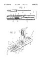
- FIG. 2 is a perspective view of a preferred embodiment of the present invention showing a stent crimping tool wherein the closing plate is in an up position and the stent-catheter assembly is shown in dashed lines.
- FIGS. 3A and 3B are perspective views showing alternative embodiments of a pad having ridges and a pad having channels that are helpful in gripping the stent.
- FIG. 4 is a perspective view of a slide having a dove tail to which a closing plate is attached.
- FIG. 5 is a perspective view of a preferred embodiment platform showing a channel designed to receive the dove tail of the slide shown in FIG. 4.
- FIG. 1 illustrates intravascular stent 10 which is mounted onto delivery catheter 11.
- Stent 10 generally comprises a plurality of radially expandable rings or cylindrical elements 12 disposed coaxially and interconnected by members 13 disposed between adjacent cylindrical elements 12.
- Delivery catheter 11 has an expandable portion or balloon 14 for expanding stent 10 within coronary artery 15 or other vessel such as saphenous veins, carotid arteries, arteries, and veins.
- Artery 15, as shown in FIG. 1, has dissected lining 16 which has occluded a portion of the arterial passageway.
- Delivery catheter 11 onto which stent 10 is mounted is essentially the same as a conventional balloon dilatation catheter for angioplasty procedures.
- Balloon 14 may be formed of suitable materials such as polyethylene, polyvinyl chloride, polyethylene terephthalate and other like polymers. In order for stent 10 to remain in place on balloon 14 during delivery to the site of the damage within artery 15, stent 10 is compressed onto balloon 14.
- An optional retractable protective delivery sleeve 20 may be provided to further ensure that stent 10 stays in place on balloon 14 of delivery catheter 11 and to prevent abrasion of the body lumen by the open surface of stent 10 during delivery to the desired arterial location.
- Other means for securing stent 10 onto balloon 14 may also be used, such as providing collars or ridges on the ends of the working portion, i.e., the cylindrical portion of balloon 14.
- stent 10 In order to implant stent 10, it is first mounted onto inflation balloon 14 on the distal extremity of delivery catheter 11. In this mounting step, stent 10 is crimped down onto balloon 14 to create a low profile.
- the present invention addresses this crimping procedure.
- the stent-catheter assembly can be introduced into the patient's vasculature through processes known in the art. Briefly, guide wire 18 is disposed across the arterial section where an angioplasty or atherectomy has been performed requiring a follow-up stenting procedure. In some cases, the arterial wall lining may be detached so that guide wire 18 is advanced past detached or dissected lining 16 and the stent-catheter assembly is advanced over guide wire 18 within artery 15 until stent 10 is directly under detached lining 16. Prior to inflation of balloon 14, delivery sleeve 20 is retracted to expose stent 10. Depending on the balloon and stent assembly, a delivery sleeve may be unnecessary. Balloon 14 of delivery catheter 11 is then inflated using an inflation fluid.
- the present invention is directed to a stent crimping tool that crimps a stent onto a balloon catheter. This is preferably accomplished through tangential forces exerted by the tool on the outside surface of the stent to slowly reduce its diameter. The diameter of the stent is continuously reduced until it is stabilized on the balloon catheter.
- FIG. 2 provides a perspective view of a preferred embodiment of the present invention stent crimping tool 22.
- Stent crimping tool 22 is comprised of base plate 24 to which is mounted stationary plate 26 at one end and platform 28 at an opposite end.
- stationary plate 26 and platform 28 are spaced apart from each other. They are formed from or firmly mounted to base plate 24 with adhesives or fasteners to prevent relative motion therebetween.
- FIG. 5 provides a perspective view of platform 28 isolated from the other parts of stent crimping tool 22.
- platform 28 preferably includes a channel 30 formed along a length thereof having twin parallel grooves 32 at the base of channel 30.
- Slide 34 is shown both in FIG. 2 and in isolation in the perspective view of FIG. 4.
- Slide 34 includes dove tail 72 that is designed to slidably engage grooves 32 and to slidably move within channel 30 of platform 28 in FIG. 5.
- dove tail 72 is designed to slidably engage grooves 32 and to slidably move within channel 30 of platform 28 in FIG. 5.
- Closing plate 36 is preferably attached to the top of slide 34 by use of hinge 38, as best seen in FIG. 2.
- Hinge 38 permits closing plate 36 to swing about two positions; namely, the up position as shown in solid lines, or the down position as shown in dashed lines.
- Hinge 38 may be loaded with an optional torsion spring, for example, to bias closing plate 36 toward the up position or the down position as needed.
- the hinge can be made of a bar of spring steel attached at opposite ends to the slide and the closing plate.
- the spring steel bar can be made to resist or to forward bias the closing plate toward either the up or the down positions.
- the bar may, of course, be made from any resilient material known in the art.
- Ridges 44, 46, 48 are intended to engage the rings or cylindrical elements 12 of stent 10. Indeed, stent 10, after being optionally hand crimped to balloon 14, is inserted laterally in a direction generally perpendicular to the direction indicated by arrow A into crimping tool 22. Ideally, each ridge 44, 46, 48 engages a corresponding cylindrical element 12 of stent 10. For example, ridges 44, 46, 48 can be situated to specifically engage the distal, proximal, and middle cylindrical elements 12 of stent 10. To be sure, it has been observed that engagement of the ridges 44, 46, 48 against cylindrical elements 12 of stent 10 helps grip the stent 10 during the crimping process.
- each spacer 50 controls the distance of gap 52, which defines the distance between the opposing pads 40, 42 of stationary plate 26 and closing plate 36, respectively. Controlling gap 52 thus controls the amount of crimp received by stent 10. Also, use of spacers 50 to define the size of gap 52 improves the chances for a precise and repeatable crimp.
- crimping tool 22 is essentially two plates 26, 36 sliding against one another.
- One of the plates 26 can be stationary while the other plate 36 is mounted on a sliding mechanism.
- the pinching action due to force F reduces the diameter of stent 10 while the sliding motion rolls the stent-catheter assembly as represented by arrow R to distribute the forces.
- optional spacers 50 controls the size of gap 52.
- a mandrel (not shown) can be inserted into delivery catheter 11 to provide a level of internal resistance in the radial direction to prevent over-crimping of stent 10 onto balloon 14.
- use of an optional mandrel positioned within the balloon 14 of catheter 11 during the crimping process ensures repeatability and a precise crimp of stent 10.
- stent crimping tool 22 To use the present invention stent crimping tool 22, the cardiologist lays a slightly hand-crimped stent-catheter assembly onto pad 42 as represented by the dashed lines of FIG. 2. Closing plate 36 is moved from its up position to the down position overlying stationary plate 26. Applying force F, which has been observed to be in the range of two to six pounds, while reciprocating and translating slide 34 along direction A cause the stent-catheter assembly to roll along direction R. As the rolling action continues, force F slowly reduces the diameter of stent 10 thus crimping it on to balloon 14 of catheter 11.
- FIGS. 3A and 3B provide perspective views of alternative embodiment pads 54, 56.
- pad 54 of FIG. 3A there are three ridges 58 corresponding to specific cylindrical elements 12 of stent 10. As mentioned earlier, these ridges or contours provide grip points on the stent that improve stability during the crimping process.
- a stop or riser 60 having vertical surface 62 against which the distal end of stent 10 abuts helps with alignment of stent 10 within tool 22. Assuming pad 54 is substituted on closing plate 36 or stationary plate 26 in place of pads 40, 42, pad 54 is oriented such that ridges 58 are parallel to ridge 48 as shown in FIG. 2. When the stent-catheter assembly is positioned on pad 54, the distal end of stent 10 abuts vertical surface 62 thus aligning stent 10 lengthwise within the force transmitting surface area of pad 54.
- Riser 60 thus acts as a stop for stent 10. The height of riser 60 is low enough to clear catheter 11 and guide wire 18 yet still abut stent 10.
- pad 56 includes channels 64 that create raised areas 66 intended to engage corresponding cylindrical elements 12 of stent 10.
- Pad 56 also includes optional riser 68 having vertical surface 70.
- the profiles of ridges 58 or channels 64 can have various shapes and dimensions.
- the ridges may be pointed as in a cone, angled as in a saw-tooth, or be rounded.
- the ridges may also be a collection of round pegs closely bunched to hold the stent.
- Other conventional geometric shapes are contemplated.
- the surface directly in contact with stent 10 during the crimping process be slightly softer than the material used on the stent to allow for yield.
- Elastomer-type materials with high durometers known in the art can be used for the pads, for example. More precisely, the contoured pads can be made from materials such as Mylar, silicone, rubber, or polycarbonate.
- the entire crimping tool or parts thereof can be made from stainless steel, aluminum, Delrin, polycarbonate, or the like.
- the present invention tool is preferably sterilized and intended to be used in a cath lab by a trained technician or cardiologist.
- the present invention crimping tool is designed both for single use applications in a cath lab by a physician, or for multiple use applications in a sterile environment in a high volume manufacturing facility.
- the present invention stent crimping tool can be used repeatedly to crimp stents onto balloons until the mechanism wears out.
- repeated uses of the present invention are contemplated for controlled, sterile environments, as are single use applications when operated by cath lab personnel.
- the present invention crimping tool can be used with any stent that is released without a delivery system.
- the crimping tool may also be sold alone, because its design is robust enough to undergo many uses.
Abstract
Description
Claims (20)
Priority Applications (3)
| Application Number | Priority Date | Filing Date | Title |
|---|---|---|---|
| US09/123,844 US6092273A (en) | 1998-07-28 | 1998-07-28 | Method and apparatus for a stent crimping device |
| PCT/US1999/017087 WO2000006052A1 (en) | 1998-07-28 | 1999-07-28 | Method and apparatus for a stent crimping device |
| AU53236/99A AU5323699A (en) | 1998-07-28 | 1999-07-28 | Method and apparatus for a stent crimping device |
Applications Claiming Priority (1)
| Application Number | Priority Date | Filing Date | Title |
|---|---|---|---|
| US09/123,844 US6092273A (en) | 1998-07-28 | 1998-07-28 | Method and apparatus for a stent crimping device |
Publications (1)
| Publication Number | Publication Date |
|---|---|
| US6092273A true US6092273A (en) | 2000-07-25 |
Family
ID=22411229
Family Applications (1)
| Application Number | Title | Priority Date | Filing Date |
|---|---|---|---|
| US09/123,844 Expired - Fee Related US6092273A (en) | 1998-07-28 | 1998-07-28 | Method and apparatus for a stent crimping device |
Country Status (3)
| Country | Link |
|---|---|
| US (1) | US6092273A (en) |
| AU (1) | AU5323699A (en) |
| WO (1) | WO2000006052A1 (en) |
Cited By (36)
| Publication number | Priority date | Publication date | Assignee | Title |
|---|---|---|---|---|
| DE10046528A1 (en) * | 2000-08-09 | 2002-02-21 | Biotronik Mess & Therapieg | Method and device for crimping a stent |
| US20020138129A1 (en) * | 1999-01-22 | 2002-09-26 | Armstrong Joseph R. | Method of producing low profile stent and graft combination |
| US6481262B2 (en) | 1999-12-30 | 2002-11-19 | Advanced Cardiovascular Systems, Inc. | Stent crimping tool |
| US6510722B1 (en) | 2000-05-10 | 2003-01-28 | Advanced Cardiovascular Systems, Inc. | Stent crimping tool for producing a grooved crimp |
| US6568235B1 (en) | 2000-08-10 | 2003-05-27 | Advanced Cardiovascular Systems, Inc. | Assembly for crimping an intraluminal device or measuring the radial strength of the intraluminal device and method of use |
| US20030135970A1 (en) * | 2000-11-16 | 2003-07-24 | Scimed Life Systems, Inc. | Bare stent ship and crimp device |
| US6640412B2 (en) | 2001-04-26 | 2003-11-04 | Endovascular Technologies, Inc. | Method for loading a stent using a collapsing machine |
| US6702845B1 (en) * | 2003-01-17 | 2004-03-09 | Gore Enterprise Holdings, Inc. | Compacted implantable medical devices and method of compacting such devices |
| US6726713B2 (en) | 2000-08-09 | 2004-04-27 | Biotronik Mess- Und Therapiegeraete Gmbh & Co. Ingenieurbuero Berlin | Method and device for crimping a stent |
| US6823576B2 (en) | 1999-09-22 | 2004-11-30 | Scimed Life Systems, Inc. | Method and apparatus for contracting, loading or crimping self-expanding and balloon expandable stent devices |
| US20050154450A1 (en) * | 2004-01-12 | 2005-07-14 | Karen Larson | Stent reducing system and device |
| US20050267562A1 (en) * | 2004-05-13 | 2005-12-01 | Medtronic Vascular, Inc. | Stent-reduction sleeve |
| US7112055B1 (en) | 2002-07-02 | 2006-09-26 | Endovascular Technologies, Inc. | Nitinol frame heating and setting mandrel |
| US20060229712A1 (en) * | 2005-04-12 | 2006-10-12 | Advanced Cardiovascular Systems, Inc. | Method of stent mounting to form a balloon catheter having improved retention of a drug delivery stent |
| WO2006127089A1 (en) | 2005-05-25 | 2006-11-30 | Boston Scientific Limited | Method and apparatus for reducing a stent |
| US20060288561A1 (en) * | 2005-06-27 | 2006-12-28 | Boston Scientific Scimed, Inc. | Crimping and edge protection elements |
| US20070032851A1 (en) * | 2005-08-02 | 2007-02-08 | Boston Scientific Scimed, Inc. | Protection by electroactive polymer sleeve |
| US20070288034A1 (en) * | 2006-06-07 | 2007-12-13 | Maccollum Michael W | Stent Expanding device |
| US20070288080A1 (en) * | 2006-06-07 | 2007-12-13 | Maccollum Michael W | Stent expanding device |
| US20080127707A1 (en) * | 2006-11-30 | 2008-06-05 | Abbott Laboratories | Stent crimping assembly and method |
| US7389670B1 (en) | 2004-07-26 | 2008-06-24 | Abbott Laboratories | Stent crimping system |
| US20090113693A1 (en) * | 2007-11-05 | 2009-05-07 | Cook Incorporated | Apparatus and method for compressing a stent |
| US20090131920A1 (en) * | 2007-11-16 | 2009-05-21 | Abbott Laboratories Vascular Enterprises Limited | Stent crimping apparatus |
| US20100043197A1 (en) * | 2008-08-01 | 2010-02-25 | Abbate Anthony J | Methods and devices for crimping self-expanding devices |
| US20100057185A1 (en) * | 2008-09-04 | 2010-03-04 | Cook Incorporated | Sliding Split-Sleeve Implant Compressor |
| US20100185207A1 (en) * | 2009-01-20 | 2010-07-22 | Abbott Laboratories Vascular Enterprises Limited | Stent crimping device |
| US20100275432A1 (en) * | 2009-02-20 | 2010-11-04 | Boston Scientific Scimed, Inc. | Locking element for vascular closure device |
| US20110004192A1 (en) * | 2005-04-04 | 2011-01-06 | Eaton Donald J | Device and methods for treating paranasal sinus conditions |
| US8221112B2 (en) | 2005-04-12 | 2012-07-17 | Abbott Cardiovascular Systems, Inc. | Method for retaining a vascular stent on a catheter |
| US8739379B2 (en) | 2007-05-11 | 2014-06-03 | Abbott Cardiovascular Systems Inc. | Crimping apparatus |
| WO2014177936A2 (en) | 2013-03-15 | 2014-11-06 | Microtech Medical Technologies Ltd. | Implantable device with bridge |
| US8986341B2 (en) | 2007-12-18 | 2015-03-24 | Intersect Ent, Inc. | Self-expanding devices and methods therefor |
| US9821091B2 (en) | 2006-06-06 | 2017-11-21 | Abbot Cardiovascular Systems Inc. | Methods of treatment of polymeric coatings for control of agent release rates |
| US10232152B2 (en) | 2013-03-14 | 2019-03-19 | Intersect Ent, Inc. | Systems, devices, and method for treating a sinus condition |
| US10357640B2 (en) | 2009-05-15 | 2019-07-23 | Intersect Ent, Inc. | Expandable devices and methods for treating a nasal or sinus condition |
| US11291812B2 (en) | 2003-03-14 | 2022-04-05 | Intersect Ent, Inc. | Sinus delivery of sustained release therapeutics |
Families Citing this family (15)
| Publication number | Priority date | Publication date | Assignee | Title |
|---|---|---|---|---|
| IT1320232B1 (en) | 2000-07-11 | 2003-11-26 | Sorin Biomedica Cardio Spa | PROCEDURE FOR COUPLING AN ANGIOPLASTIC STENT WITH AN ADDITIONAL INSERTION ELEMENT AND SO ACCOMPANYING FORMAT. |
| ITTO20040135A1 (en) | 2004-03-03 | 2004-06-03 | Sorin Biomedica Cardio Spa | CARDIAC VALVE PROSTHESIS |
| ITTO20050074A1 (en) | 2005-02-10 | 2006-08-11 | Sorin Biomedica Cardio Srl | CARDIAC VALVE PROSTHESIS |
| US8006535B2 (en) | 2007-07-12 | 2011-08-30 | Sorin Biomedica Cardio S.R.L. | Expandable prosthetic valve crimping device |
| EP2229921B1 (en) | 2007-07-12 | 2014-11-12 | Sorin Group Italia S.r.l. | Expandable prosthetic valve crimping device |
| US9848981B2 (en) | 2007-10-12 | 2017-12-26 | Mayo Foundation For Medical Education And Research | Expandable valve prosthesis with sealing mechanism |
| EP2682072A1 (en) | 2008-12-23 | 2014-01-08 | Sorin Group Italia S.r.l. | Expandable prosthetic valve having anchoring appendages |
| US8715207B2 (en) | 2009-03-19 | 2014-05-06 | Sorin Group Italia S.R.L. | Universal valve annulus sizing device |
| US20100262043A1 (en) | 2009-03-26 | 2010-10-14 | Sorin Group Usa, Inc. | Annuloplasty sizers for minimally invasive procedures |
| IT1400327B1 (en) | 2010-05-21 | 2013-05-24 | Sorin Biomedica Cardio Srl | SUPPORT DEVICE FOR VALVULAR PROSTHESIS AND CORRESPONDING CORRESPONDENT. |
| ES2641902T3 (en) | 2011-02-14 | 2017-11-14 | Sorin Group Italia S.R.L. | Sutureless anchoring device for cardiac valve prostheses |
| EP2486894B1 (en) | 2011-02-14 | 2021-06-09 | Sorin Group Italia S.r.l. | Sutureless anchoring device for cardiac valve prostheses |
| US9125763B2 (en) | 2013-03-15 | 2015-09-08 | Abbott Cardiovascular Systems Inc. | Stent crimping tool insert, system, and method |
| WO2019224582A1 (en) | 2018-05-23 | 2019-11-28 | Sorin Group Italia S.R.L. | A loading system for an implantable prosthesis and related loading method |
| JP7109657B2 (en) | 2018-05-23 | 2022-07-29 | コーシム・ソチエタ・ア・レスポンサビリタ・リミタータ | heart valve prosthesis |
Citations (31)
| Publication number | Priority date | Publication date | Assignee | Title |
|---|---|---|---|---|
| US696289A (en) * | 1901-07-26 | 1902-03-25 | Maryland Shoe Machinery Company | Machine for inserting protectors in heels and soles of shoes. |
| GB159065A (en) * | 1919-12-09 | 1921-02-24 | William Levi Secord | Improvements relating to machine and other vices and like work holding or setting appliances |
| US4468224A (en) * | 1982-01-28 | 1984-08-28 | Advanced Cardiovascular Systems, Inc. | System and method for catheter placement in blood vessels of a human patient |
| US4546646A (en) * | 1982-10-01 | 1985-10-15 | Fuji Jukogyo Kabushiki Kaisha | System for diagnosing an internal combustion engine |
| US4576142A (en) * | 1982-11-19 | 1986-03-18 | Peter Schiff | Percutaneous intra-aortic balloon and method for using same |
| US4644936A (en) * | 1982-11-19 | 1987-02-24 | Iabp | Percutaneous intra-aortic balloon and method for using same |
| US4681092A (en) * | 1985-05-21 | 1987-07-21 | Kontron Inc. | Balloon catheter wrapping apparatus |
| US4697573A (en) * | 1982-11-19 | 1987-10-06 | Iabp Corporation | Percutaneous intra-aortic balloon and method for using same |
| US4901707A (en) * | 1982-11-19 | 1990-02-20 | Iabp Corporation | Prepackaged intra-aortic balloon assembly with holder, and method of using same |
| US4907336A (en) * | 1987-03-13 | 1990-03-13 | Cook Incorporated | Method of making an endovascular stent and delivery system |
| US5189786A (en) * | 1990-11-13 | 1993-03-02 | Sumitomo Wiring Systems, Ltd. | Electrical cable stripping method and electrical cable loosening device |
| US5437083A (en) * | 1993-05-24 | 1995-08-01 | Advanced Cardiovascular Systems, Inc. | Stent-loading mechanism |
| US5626604A (en) * | 1995-12-05 | 1997-05-06 | Cordis Corporation | Hand held stent crimping device |
| US5653691A (en) * | 1996-04-25 | 1997-08-05 | Rupp; Garry Eugene | Thickened inner lumen for uniform stent expansion and method of making |
| US5672169A (en) * | 1996-04-10 | 1997-09-30 | Medtronic, Inc. | Stent mounting device |
| US5693066A (en) * | 1995-12-21 | 1997-12-02 | Medtronic, Inc. | Stent mounting and transfer device and method |
| WO1998014120A1 (en) * | 1996-09-30 | 1998-04-09 | Medtronic Instent Israel Ltd. | Stent loading device for a balloon catheter |
| US5746764A (en) * | 1995-12-04 | 1998-05-05 | Atrion Medical Products, Inc. | Stent compression instrument |
| WO1998019633A1 (en) * | 1996-11-06 | 1998-05-14 | Percusurge, Inc. | Apparatus and method for loading a stent on a catheter |
| US5782903A (en) * | 1987-10-19 | 1998-07-21 | Medtronic, Inc. | Intravascular stent and method |
| US5782855A (en) * | 1991-01-28 | 1998-07-21 | Advanced Cardiovascular Systems, Inc. | Stent delivery system |
| US5783227A (en) * | 1996-01-22 | 1998-07-21 | Cordis Corporation | Catheter balloon folding device |
| US5785715A (en) * | 1995-12-07 | 1998-07-28 | Schatz; Richard A. | Retrieval shuttle |
| US5810871A (en) * | 1997-04-29 | 1998-09-22 | Medtronic, Inc. | Stent delivery system |
| US5810838A (en) * | 1997-03-13 | 1998-09-22 | Solar; Ronald J. | Hydraulic method and apparatus for uniform radial compression and catheter mounting of radially expandable intraluminal stents and stented grafts |
| US5836952A (en) * | 1996-08-21 | 1998-11-17 | Cordis Corporation | Hand-held stent crimper |
| US5920975A (en) * | 1997-11-03 | 1999-07-13 | Advanced Cardiovascular Systems, Inc. | Stent crimping tool and method of use |
| US5931851A (en) * | 1998-04-21 | 1999-08-03 | Advanced Cardiovascular Systems, Inc. | Method and apparatus for rubber-tube crimping tool with premount stent |
| US5948191A (en) * | 1996-07-15 | 1999-09-07 | Cordis Corporation | Low profile, thermally set wrapped cover for a percutaneously deployed stent |
| US5947993A (en) * | 1997-07-15 | 1999-09-07 | Advanced Cardiovascular Systems, Inc. | Stent crimping tool and method of use |
| US6024737A (en) * | 1998-02-25 | 2000-02-15 | Advanced Cardiovascular Systems, Inc. | Stent crimping device |
-
1998
- 1998-07-28 US US09/123,844 patent/US6092273A/en not_active Expired - Fee Related
-
1999
- 1999-07-28 WO PCT/US1999/017087 patent/WO2000006052A1/en active Application Filing
- 1999-07-28 AU AU53236/99A patent/AU5323699A/en not_active Abandoned
Patent Citations (35)
| Publication number | Priority date | Publication date | Assignee | Title |
|---|---|---|---|---|
| US696289A (en) * | 1901-07-26 | 1902-03-25 | Maryland Shoe Machinery Company | Machine for inserting protectors in heels and soles of shoes. |
| GB159065A (en) * | 1919-12-09 | 1921-02-24 | William Levi Secord | Improvements relating to machine and other vices and like work holding or setting appliances |
| US4468224A (en) * | 1982-01-28 | 1984-08-28 | Advanced Cardiovascular Systems, Inc. | System and method for catheter placement in blood vessels of a human patient |
| US4546646A (en) * | 1982-10-01 | 1985-10-15 | Fuji Jukogyo Kabushiki Kaisha | System for diagnosing an internal combustion engine |
| US4901707A (en) * | 1982-11-19 | 1990-02-20 | Iabp Corporation | Prepackaged intra-aortic balloon assembly with holder, and method of using same |
| US4576142A (en) * | 1982-11-19 | 1986-03-18 | Peter Schiff | Percutaneous intra-aortic balloon and method for using same |
| US4644936A (en) * | 1982-11-19 | 1987-02-24 | Iabp | Percutaneous intra-aortic balloon and method for using same |
| US4697573A (en) * | 1982-11-19 | 1987-10-06 | Iabp Corporation | Percutaneous intra-aortic balloon and method for using same |
| US4681092A (en) * | 1985-05-21 | 1987-07-21 | Kontron Inc. | Balloon catheter wrapping apparatus |
| US4907336A (en) * | 1987-03-13 | 1990-03-13 | Cook Incorporated | Method of making an endovascular stent and delivery system |
| US5782903A (en) * | 1987-10-19 | 1998-07-21 | Medtronic, Inc. | Intravascular stent and method |
| US5189786A (en) * | 1990-11-13 | 1993-03-02 | Sumitomo Wiring Systems, Ltd. | Electrical cable stripping method and electrical cable loosening device |
| US5782855A (en) * | 1991-01-28 | 1998-07-21 | Advanced Cardiovascular Systems, Inc. | Stent delivery system |
| US5437083A (en) * | 1993-05-24 | 1995-08-01 | Advanced Cardiovascular Systems, Inc. | Stent-loading mechanism |
| US5738674A (en) * | 1993-05-24 | 1998-04-14 | Advanced Cardiovascular Systems, Inc. | Stent loading mechanism |
| US5746764A (en) * | 1995-12-04 | 1998-05-05 | Atrion Medical Products, Inc. | Stent compression instrument |
| US5944735A (en) * | 1995-12-04 | 1999-08-31 | Atrion Medical Products, Inc. | Process for stent compression |
| US5626604A (en) * | 1995-12-05 | 1997-05-06 | Cordis Corporation | Hand held stent crimping device |
| US5785715A (en) * | 1995-12-07 | 1998-07-28 | Schatz; Richard A. | Retrieval shuttle |
| US5693066A (en) * | 1995-12-21 | 1997-12-02 | Medtronic, Inc. | Stent mounting and transfer device and method |
| US5783227A (en) * | 1996-01-22 | 1998-07-21 | Cordis Corporation | Catheter balloon folding device |
| US5672169A (en) * | 1996-04-10 | 1997-09-30 | Medtronic, Inc. | Stent mounting device |
| US5653691A (en) * | 1996-04-25 | 1997-08-05 | Rupp; Garry Eugene | Thickened inner lumen for uniform stent expansion and method of making |
| US5948191A (en) * | 1996-07-15 | 1999-09-07 | Cordis Corporation | Low profile, thermally set wrapped cover for a percutaneously deployed stent |
| US5836952A (en) * | 1996-08-21 | 1998-11-17 | Cordis Corporation | Hand-held stent crimper |
| WO1998014120A1 (en) * | 1996-09-30 | 1998-04-09 | Medtronic Instent Israel Ltd. | Stent loading device for a balloon catheter |
| US5893867A (en) * | 1996-11-06 | 1999-04-13 | Percusurge, Inc. | Stent positioning apparatus and method |
| WO1998019633A1 (en) * | 1996-11-06 | 1998-05-14 | Percusurge, Inc. | Apparatus and method for loading a stent on a catheter |
| US5810838A (en) * | 1997-03-13 | 1998-09-22 | Solar; Ronald J. | Hydraulic method and apparatus for uniform radial compression and catheter mounting of radially expandable intraluminal stents and stented grafts |
| US5810871A (en) * | 1997-04-29 | 1998-09-22 | Medtronic, Inc. | Stent delivery system |
| US5951569A (en) * | 1997-04-29 | 1999-09-14 | Medtronic, Inc. | Stent delivery system |
| US5947993A (en) * | 1997-07-15 | 1999-09-07 | Advanced Cardiovascular Systems, Inc. | Stent crimping tool and method of use |
| US5920975A (en) * | 1997-11-03 | 1999-07-13 | Advanced Cardiovascular Systems, Inc. | Stent crimping tool and method of use |
| US6024737A (en) * | 1998-02-25 | 2000-02-15 | Advanced Cardiovascular Systems, Inc. | Stent crimping device |
| US5931851A (en) * | 1998-04-21 | 1999-08-03 | Advanced Cardiovascular Systems, Inc. | Method and apparatus for rubber-tube crimping tool with premount stent |
Non-Patent Citations (13)
| Title |
|---|
| The eXTraordinary Stent, C.R. Bard Brochure (Undated). * |
| U.S. Patent Application Serial No. 08/795,335 filed Feb. 4, 1997. * |
| U.S. Patent Application Serial No. 08/837,771 filed Apr. 22, 1997. * |
| U.S. Patent Application Serial No. 08/893,936 filed Jul. 15, 1997. * |
| U.S. Patent Application Serial No. 08/962,632 filed Nov. 3, 1997. * |
| U.S. Patent Application Serial No. 09/024,910 filed Feb. 17, 1998. * |
| U.S. Patent Application Serial No. 09/030,261 filed Feb. 25, 1998. * |
| U.S. Patent Application Serial No. 09/063,587 filed Apr. 21, 1998. * |
| U.S. Patent Application Serial No. 09/063,905 filed Apr. 21, 1998. * |
| U.S. Patent Application Serial No. 09/069,010 filed Apr. 28, 1998. * |
| U.S. Patent Application Serial No. 09/069,011 filed Apr. 28, 1998. * |
| U.S. Patent Application Serial No. 09/072,925 filed May 5, 1998. * |
| U.S. Patent Application Serial No. 09/169,270 filed Oct. 9, 1998. * |
Cited By (78)
| Publication number | Priority date | Publication date | Assignee | Title |
|---|---|---|---|---|
| US20060015167A1 (en) * | 1999-01-22 | 2006-01-19 | Armstrong Joseph R | Method of producing low profile stent and graft combination |
| US20020138129A1 (en) * | 1999-01-22 | 2002-09-26 | Armstrong Joseph R. | Method of producing low profile stent and graft combination |
| US9056001B2 (en) | 1999-01-22 | 2015-06-16 | W. L. Gore & Associates, Inc. | Method of producing low profile stent and graft combination |
| US6981982B2 (en) | 1999-01-22 | 2006-01-03 | Gore Enterprise Holdings, Inc. | Method of producing low profile stent and graft combination |
| US20100011976A1 (en) * | 1999-01-22 | 2010-01-21 | Armstrong Joseph A | Method of Producing Low Profile Stent and Graft Combination |
| US7691109B2 (en) | 1999-01-22 | 2010-04-06 | Gore Enterprise Holdings, Inc. | Method of producing low profile stent and graft combination |
| US8533925B2 (en) | 1999-09-22 | 2013-09-17 | Boston Scientific Scimed, Inc. | Method for contracting or crimping stents |
| US20100154195A1 (en) * | 1999-09-22 | 2010-06-24 | Boston Scientific Scimed, Inc. | Method and apparatus for contracting, or crimping stents |
| US7587801B2 (en) | 1999-09-22 | 2009-09-15 | Boston Scientific Scimed, Inc. | Stent crimper |
| US6823576B2 (en) | 1999-09-22 | 2004-11-30 | Scimed Life Systems, Inc. | Method and apparatus for contracting, loading or crimping self-expanding and balloon expandable stent devices |
| US6915560B2 (en) | 1999-09-22 | 2005-07-12 | Boston Scientific Scimed, Inc. | Apparatus for contracting, loading or crimping self-expanding and balloon expandable stent devices |
| US7992273B2 (en) | 1999-09-22 | 2011-08-09 | Boston Scientific Scimed, Inc. | Crimping apparatus for reducing size of a stent |
| US20050240256A1 (en) * | 1999-09-22 | 2005-10-27 | Boston Scientific Scimed, Inc. | Method and apparatus for contracting, loading or crimping self-expanding and balloon expandable stent devices |
| US6481262B2 (en) | 1999-12-30 | 2002-11-19 | Advanced Cardiovascular Systems, Inc. | Stent crimping tool |
| US6510722B1 (en) | 2000-05-10 | 2003-01-28 | Advanced Cardiovascular Systems, Inc. | Stent crimping tool for producing a grooved crimp |
| US6726713B2 (en) | 2000-08-09 | 2004-04-27 | Biotronik Mess- Und Therapiegeraete Gmbh & Co. Ingenieurbuero Berlin | Method and device for crimping a stent |
| DE10046528A1 (en) * | 2000-08-09 | 2002-02-21 | Biotronik Mess & Therapieg | Method and device for crimping a stent |
| US6651478B1 (en) | 2000-08-10 | 2003-11-25 | Advanced Cardiovascular Systems, Inc. | Assembly for crimping an intraluminal device or measuring the radial strength of the intraluminal device and method of use |
| US6568235B1 (en) | 2000-08-10 | 2003-05-27 | Advanced Cardiovascular Systems, Inc. | Assembly for crimping an intraluminal device or measuring the radial strength of the intraluminal device and method of use |
| US6920674B2 (en) | 2000-11-16 | 2005-07-26 | Scimed Life Systems, Inc. | Bare stent ship and crimp device |
| US6618921B1 (en) | 2000-11-16 | 2003-09-16 | Scimed Life Systems, Inc. | Bare stent ship and crimp device |
| US20030135970A1 (en) * | 2000-11-16 | 2003-07-24 | Scimed Life Systems, Inc. | Bare stent ship and crimp device |
| US6640412B2 (en) | 2001-04-26 | 2003-11-04 | Endovascular Technologies, Inc. | Method for loading a stent using a collapsing machine |
| US7708925B2 (en) | 2002-07-02 | 2010-05-04 | Abbott Vascular Solutions Inc. | Nitinol frame heating and setting mandrel |
| US7112055B1 (en) | 2002-07-02 | 2006-09-26 | Endovascular Technologies, Inc. | Nitinol frame heating and setting mandrel |
| US20060267247A1 (en) * | 2002-07-02 | 2006-11-30 | Boris Anukhin | Nitinol frame heating and setting mandrel |
| US6702845B1 (en) * | 2003-01-17 | 2004-03-09 | Gore Enterprise Holdings, Inc. | Compacted implantable medical devices and method of compacting such devices |
| US11291812B2 (en) | 2003-03-14 | 2022-04-05 | Intersect Ent, Inc. | Sinus delivery of sustained release therapeutics |
| US7284401B2 (en) | 2004-01-12 | 2007-10-23 | Boston Scientific Scimed, Inc. | Stent reducing system and device |
| US20050154450A1 (en) * | 2004-01-12 | 2005-07-14 | Karen Larson | Stent reducing system and device |
| WO2005070335A1 (en) | 2004-01-12 | 2005-08-04 | Boston Scientific Limited | Stent reducing system |
| US20050267562A1 (en) * | 2004-05-13 | 2005-12-01 | Medtronic Vascular, Inc. | Stent-reduction sleeve |
| US7628051B1 (en) | 2004-07-26 | 2009-12-08 | Abbott Laboratories | Stent crimping system |
| US8215149B1 (en) | 2004-07-26 | 2012-07-10 | Abbott Laboratories | Stent crimping system and method |
| US7389670B1 (en) | 2004-07-26 | 2008-06-24 | Abbott Laboratories | Stent crimping system |
| US11123091B2 (en) | 2005-04-04 | 2021-09-21 | Intersect Ent, Inc. | Device and methods for treating paranasal sinus conditions |
| US8858974B2 (en) | 2005-04-04 | 2014-10-14 | Intersect Ent, Inc. | Device and methods for treating paranasal sinus conditions |
| US9585681B2 (en) | 2005-04-04 | 2017-03-07 | Intersect Ent, Inc. | Device and methods for treating paranasal sinus conditions |
| US20110004192A1 (en) * | 2005-04-04 | 2011-01-06 | Eaton Donald J | Device and methods for treating paranasal sinus conditions |
| US20090259289A1 (en) * | 2005-04-12 | 2009-10-15 | Advanced Cardiovascular Systems, Inc. | Method of stent mounting to form a balloon catheter having improved retention of a drug delivery stent |
| US20060229712A1 (en) * | 2005-04-12 | 2006-10-12 | Advanced Cardiovascular Systems, Inc. | Method of stent mounting to form a balloon catheter having improved retention of a drug delivery stent |
| US8221112B2 (en) | 2005-04-12 | 2012-07-17 | Abbott Cardiovascular Systems, Inc. | Method for retaining a vascular stent on a catheter |
| WO2006127089A1 (en) | 2005-05-25 | 2006-11-30 | Boston Scientific Limited | Method and apparatus for reducing a stent |
| US20060288561A1 (en) * | 2005-06-27 | 2006-12-28 | Boston Scientific Scimed, Inc. | Crimping and edge protection elements |
| US8099851B2 (en) | 2005-06-27 | 2012-01-24 | Boston Scientific Scimed, Inc. | Crimping and edge protection elements |
| US20070032851A1 (en) * | 2005-08-02 | 2007-02-08 | Boston Scientific Scimed, Inc. | Protection by electroactive polymer sleeve |
| US9821091B2 (en) | 2006-06-06 | 2017-11-21 | Abbot Cardiovascular Systems Inc. | Methods of treatment of polymeric coatings for control of agent release rates |
| US20070288080A1 (en) * | 2006-06-07 | 2007-12-13 | Maccollum Michael W | Stent expanding device |
| US20070288034A1 (en) * | 2006-06-07 | 2007-12-13 | Maccollum Michael W | Stent Expanding device |
| US20080127707A1 (en) * | 2006-11-30 | 2008-06-05 | Abbott Laboratories | Stent crimping assembly and method |
| US8739379B2 (en) | 2007-05-11 | 2014-06-03 | Abbott Cardiovascular Systems Inc. | Crimping apparatus |
| US20090113693A1 (en) * | 2007-11-05 | 2009-05-07 | Cook Incorporated | Apparatus and method for compressing a stent |
| US8256263B2 (en) | 2007-11-05 | 2012-09-04 | Cook Medical Technologies Llc | Apparatus and method for compressing a stent |
| US20090131920A1 (en) * | 2007-11-16 | 2009-05-21 | Abbott Laboratories Vascular Enterprises Limited | Stent crimping apparatus |
| US8986341B2 (en) | 2007-12-18 | 2015-03-24 | Intersect Ent, Inc. | Self-expanding devices and methods therefor |
| US10471185B2 (en) | 2007-12-18 | 2019-11-12 | Intersect Ent, Inc. | Self-expanding devices and methods therefor |
| US11826494B2 (en) | 2007-12-18 | 2023-11-28 | Intersect Ent, Inc. | Self-expanding devices and methods therefor |
| US11654216B2 (en) | 2007-12-18 | 2023-05-23 | Intersect Ent, Inc. | Self-expanding devices and methods therefor |
| US11110210B2 (en) | 2007-12-18 | 2021-09-07 | Intersect Ent, Inc. | Self-expanding devices and methods therefor |
| US11497835B2 (en) | 2007-12-18 | 2022-11-15 | Intersect Ent, Inc. | Self-expanding devices and methods therefor |
| US10010651B2 (en) | 2007-12-18 | 2018-07-03 | Intersect Ent, Inc. | Self-expanding devices and methods therefor |
| US9782283B2 (en) | 2008-08-01 | 2017-10-10 | Intersect Ent, Inc. | Methods and devices for crimping self-expanding devices |
| US8763222B2 (en) | 2008-08-01 | 2014-07-01 | Intersect Ent, Inc. | Methods and devices for crimping self-expanding devices |
| US20100043197A1 (en) * | 2008-08-01 | 2010-02-25 | Abbate Anthony J | Methods and devices for crimping self-expanding devices |
| US20100057185A1 (en) * | 2008-09-04 | 2010-03-04 | Cook Incorporated | Sliding Split-Sleeve Implant Compressor |
| US8359721B2 (en) * | 2008-09-04 | 2013-01-29 | Cook Medical Technologies Llc | Sliding split-sleeve implant compressor |
| US20100185207A1 (en) * | 2009-01-20 | 2010-07-22 | Abbott Laboratories Vascular Enterprises Limited | Stent crimping device |
| US8112857B2 (en) | 2009-01-20 | 2012-02-14 | Abbott Laboratories Vascular Enterprises Limited | Stent crimping device |
| US20100275432A1 (en) * | 2009-02-20 | 2010-11-04 | Boston Scientific Scimed, Inc. | Locking element for vascular closure device |
| US8375553B2 (en) * | 2009-02-20 | 2013-02-19 | Boston Scientific Scimed, Inc. | Locking element for vascular closure device |
| US10357640B2 (en) | 2009-05-15 | 2019-07-23 | Intersect Ent, Inc. | Expandable devices and methods for treating a nasal or sinus condition |
| US11484693B2 (en) | 2009-05-15 | 2022-11-01 | Intersect Ent, Inc. | Expandable devices and methods for treating a nasal or sinus condition |
| US10406332B2 (en) | 2013-03-14 | 2019-09-10 | Intersect Ent, Inc. | Systems, devices, and method for treating a sinus condition |
| US10232152B2 (en) | 2013-03-14 | 2019-03-19 | Intersect Ent, Inc. | Systems, devices, and method for treating a sinus condition |
| US11672960B2 (en) | 2013-03-14 | 2023-06-13 | Intersect Ent, Inc. | Systems, devices, and method for treating a sinus condition |
| US11160506B2 (en) | 2013-03-15 | 2021-11-02 | Microtech Medical Technologies Ltd | Implantable device with bridge |
| US10238339B2 (en) | 2013-03-15 | 2019-03-26 | Microtech Medical Technologies Ltd. | Implantable device with bridge |
| WO2014177936A2 (en) | 2013-03-15 | 2014-11-06 | Microtech Medical Technologies Ltd. | Implantable device with bridge |
Also Published As
| Publication number | Publication date |
|---|---|
| WO2000006052A1 (en) | 2000-02-10 |
| AU5323699A (en) | 2000-02-21 |
Similar Documents
| Publication | Publication Date | Title |
|---|---|---|
| US6092273A (en) | Method and apparatus for a stent crimping device | |
| US6125523A (en) | Stent crimping tool and method of use | |
| US5931851A (en) | Method and apparatus for rubber-tube crimping tool with premount stent | |
| US6141855A (en) | Stent crimping tool and method of use | |
| US6082990A (en) | Stent crimping tool | |
| US6009614A (en) | Stent crimping tool and method of use | |
| US6167605B1 (en) | Collet type crimping tool | |
| US6640412B2 (en) | Method for loading a stent using a collapsing machine | |
| US5974652A (en) | Method and apparatus for uniformly crimping a stent onto a catheter | |
| US7308748B2 (en) | Method for compressing an intraluminal device | |
| US5893852A (en) | Stent crimping tool and method of use | |
| US5437083A (en) | Stent-loading mechanism | |
| US6651478B1 (en) | Assembly for crimping an intraluminal device or measuring the radial strength of the intraluminal device and method of use | |
| US5920975A (en) | Stent crimping tool and method of use | |
| US6840081B2 (en) | Assembly for crimping an intraluminal device or measuring the radial strength of the intraluminal device and method of use | |
| US5810873A (en) | Stent crimping tool and method of use | |
| US6024737A (en) | Stent crimping device | |
| US8112857B2 (en) | Stent crimping device |
Legal Events
| Date | Code | Title | Description |
|---|---|---|---|
| AS | Assignment |
Owner name: ADVANCED CARDIOVASCULAR SYSTEMS, INC., CALIFORNIA Free format text: ASSIGNMENT OF ASSIGNORS INTEREST;ASSIGNOR:VILLAREAL, PLARIDEL K.;REEL/FRAME:009361/0562 Effective date: 19980708 |
|
| CC | Certificate of correction | ||
| FEPP | Fee payment procedure |
Free format text: PAYOR NUMBER ASSIGNED (ORIGINAL EVENT CODE: ASPN); ENTITY STATUS OF PATENT OWNER: LARGE ENTITY Free format text: PAYER NUMBER DE-ASSIGNED (ORIGINAL EVENT CODE: RMPN); ENTITY STATUS OF PATENT OWNER: LARGE ENTITY |
|
| FPAY | Fee payment |
Year of fee payment: 4 |
|
| REMI | Maintenance fee reminder mailed | ||
| LAPS | Lapse for failure to pay maintenance fees | ||
| STCH | Information on status: patent discontinuation |
Free format text: PATENT EXPIRED DUE TO NONPAYMENT OF MAINTENANCE FEES UNDER 37 CFR 1.362 |
|
| FP | Lapsed due to failure to pay maintenance fee |
Effective date: 20080725 |