US6093979A - Channel expander for remotely controlled automotive security and convenience systems - Google Patents
Channel expander for remotely controlled automotive security and convenience systems Download PDFInfo
- Publication number
- US6093979A US6093979A US09/318,207 US31820799A US6093979A US 6093979 A US6093979 A US 6093979A US 31820799 A US31820799 A US 31820799A US 6093979 A US6093979 A US 6093979A
- Authority
- US
- United States
- Prior art keywords
- expander
- output
- mode
- controller
- response
- Prior art date
- Legal status (The legal status is an assumption and is not a legal conclusion. Google has not performed a legal analysis and makes no representation as to the accuracy of the status listed.)
- Expired - Fee Related
Links
Images

Classifications
-
- B—PERFORMING OPERATIONS; TRANSPORTING
- B60—VEHICLES IN GENERAL
- B60R—VEHICLES, VEHICLE FITTINGS, OR VEHICLE PARTS, NOT OTHERWISE PROVIDED FOR
- B60R25/00—Fittings or systems for preventing or indicating unauthorised use or theft of vehicles
- B60R25/20—Means to switch the anti-theft system on or off
- B60R25/24—Means to switch the anti-theft system on or off using electronic identifiers containing a code not memorised by the user
-
- G—PHYSICS
- G07—CHECKING-DEVICES
- G07C—TIME OR ATTENDANCE REGISTERS; REGISTERING OR INDICATING THE WORKING OF MACHINES; GENERATING RANDOM NUMBERS; VOTING OR LOTTERY APPARATUS; ARRANGEMENTS, SYSTEMS OR APPARATUS FOR CHECKING NOT PROVIDED FOR ELSEWHERE
- G07C9/00—Individual registration on entry or exit
- G07C9/00174—Electronically operated locks; Circuits therefor; Nonmechanical keys therefor, e.g. passive or active electrical keys or other data carriers without mechanical keys
- G07C9/00182—Electronically operated locks; Circuits therefor; Nonmechanical keys therefor, e.g. passive or active electrical keys or other data carriers without mechanical keys operated with unidirectional data transmission between data carrier and locks
- G07C2009/00261—Electronically operated locks; Circuits therefor; Nonmechanical keys therefor, e.g. passive or active electrical keys or other data carriers without mechanical keys operated with unidirectional data transmission between data carrier and locks the keyless data carrier having more than one function
-
- G—PHYSICS
- G07—CHECKING-DEVICES
- G07C—TIME OR ATTENDANCE REGISTERS; REGISTERING OR INDICATING THE WORKING OF MACHINES; GENERATING RANDOM NUMBERS; VOTING OR LOTTERY APPARATUS; ARRANGEMENTS, SYSTEMS OR APPARATUS FOR CHECKING NOT PROVIDED FOR ELSEWHERE
- G07C9/00—Individual registration on entry or exit
- G07C9/00174—Electronically operated locks; Circuits therefor; Nonmechanical keys therefor, e.g. passive or active electrical keys or other data carriers without mechanical keys
- G07C2009/00753—Electronically operated locks; Circuits therefor; Nonmechanical keys therefor, e.g. passive or active electrical keys or other data carriers without mechanical keys operated by active electrical keys
- G07C2009/00769—Electronically operated locks; Circuits therefor; Nonmechanical keys therefor, e.g. passive or active electrical keys or other data carriers without mechanical keys operated by active electrical keys with data transmission performed by wireless means
- G07C2009/00793—Electronically operated locks; Circuits therefor; Nonmechanical keys therefor, e.g. passive or active electrical keys or other data carriers without mechanical keys operated by active electrical keys with data transmission performed by wireless means by Hertzian waves
Definitions
- This invention relates to systems having the capability of remotely operating electronic functions of a vehicle.
- the device of the present invention allows the operator to control a number of functions in a system exceeding a limited number of control outputs of said system.
- Some of the features of the automotive security and convenience systems include the ability to lock and unlock doors, fully or partially roll down windows, turn on lights of the vehicle and the like.
- the automotive security and convenience systems presently sold have a limited number of remotely controlled outputs (output channels).
- output channels remotely controlled outputs
- some applications require more output channels than available in the chosen security and convenience system. Therefore, these applications employ channel expanders that allow one output channel to expand and control multiple outputs.
- Channel expanders have been known and used in the industry. Generally they allow one output channel to be expanded to control a number of channels.
- the channel expanders of the prior art are not user friendly. As an example, in a six-channel expander of the prior art, the unit resets to expander output one after its function is performed. Therefore, if the user commonly used expander output three, he/she would have to access that output by pressing buttons on his/her remote control multiple times. This is tedious and at times involves misapplication and operation of an undesired output or function such as rolling windows down while it is raining.
- Another undesirable feature of the prior art expanders is that the user must scroll through the unused expander outputs prior to reaching the desired channel. More particularly, if the channel expander has ten outputs, only three of which are utilized, then to control output two, immediately after controlling output three, the user must scroll or loop through eight outputs, i.e. outputs four through one.
- the device of the present invention overcomes the above-described deficiencies in the prior art.
- the device of the present invention has a selectable "memory-mode" such that the device does not reset to channel one automatically. Instead, it remembers the last expander output called by the remote transmitter and thereafter it defaults and operates that output again unless another output is selected.
- the device of the present invention has an "off-mode". This mode allows the user to delete the unused expander outputs from its loop. Therefore, in a ten-output expander, where only three outputs are used, the loop consists of scrolling from output one to output two to output three and back to output one. The user is not compelled to scroll through inactive and unassigned expander outputs four through ten just to get to channel one.
- each of the channel expander outputs is programmable to one of multiple states/modes.
- One of the modes is an "off-mode".
- the "off-mode” makes that output unused and the user thereafter does not have to scroll through it to reach another output.
- the next mode is a "latch-mode”.
- "Latch-mode” turns outputs on and off and remains in the assigned on or off state until changed again.
- the next mode is the "timed-mode”. This mode turns an output on for a period of time such as thirty-seconds timed, sixty-seconds timed and/or ninety-seconds timed, although it can be any period of time. This state is useful for activating lights or any other device for a period of time.
- Another mode is "latch-reset-with-ignition-mode". This mode is an on/off switch. When this type of output is used, it will turn on if it was off, or off if it was on. It will only change states if it is accessed again.
- Another mode is "validity-mode”. This mode provides a signal as long as the button(s) of the remote control is being activated or pressed.
- the last mode is a “pulse-mode”. This mode operates a function upon depression and release of a button on the remote control transmitter. The result is a control signal for a period of one second.
- the pulse and validity modes are default modes of the present invention.
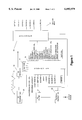
- FIG. 1 is a representation of the block diagram of the present invention.
- FIG. 2 is an alternate embodiment of the present invention having a resident RF antenna, receiver and decoder therewith.
- FIG. 1 is a block diagram of the present invention.
- the system of the present invention consists of three broad components: remote control transmitter 25, controller module 35 and channel expander 55.
- Transmitter 25 customarily employs at least two switches/buttons 26. With two switches one can activate three different channels/commands, i.e. by activating button one, button two, and button one and two.
- the signal is received and decoded by controller 35 via controller antenna 31 and RF receiver 33, fed by vehicle power that is filtered and regulated via filter regulator 39 and RC-filter 41.
- controller 35 Inside controller 35 is a decoder 30 that decodes the digital information from the signal into its various components.
- decoder 30 decodes the digital information from the signal into its various components.
- controller 35 Before controller 35 responds to the commands that it received it checks the security code of the issuing transmitter 25 and compares it to a table of authorized security codes programmed therein.
- the memory storing these authorized codes may be local to controller 35 or reside in an EEPROM 37. Multiple transmitters 25 may be programmed to operate controller 35.
- channel one command in response to activation of button one in transmitter 25, is an arm-disarm command. It arms and disarms the alarm system and controller 35.
- Channel two command in response to activation of button two in transmitter 25, is a time delay channel. This is ordinarily used to release the trunk latch. In the preferred embodiment a 1.5-second delay is employed so that an accidental push of button two does not release the trunk.
- channel three is usually an instant trigger channel capable of operating other functions about the vehicle.
- the system shown in FIG. 1 has six output channels. Other systems may have more or less output channels.
- Expander 55 may employ one to ⁇ n ⁇ outputs. These expanders may also be cascaded to achieve higher channel counts.
- expander trigger output In the preferred embodiment via controller channel three.
- the instant output signal of expander trigger output triggers or wakes expander 55 to count the number of times controller channel-three command, resulting in expander-trigger-output, was activated by transmitter 25. Accordingly, if expander trigger output is activated once, expander 55 will recognize it to trigger its expander output one. If expander output trigger is activated consecutively twice, expander 55 will recognize it to trigger its expander output two. If expander trigger output is activated three times, expander 55 will recognize it to trigger its expander output three, . . . etc.
- expander 55 is activated by transmitting channel three command from remote transmitter 25 that in turn activates expander trigger output of controller 35. Expander 55 receives this output. Before deciding which of the ⁇ n ⁇ expander outputs the user wanted to command, it will count the number of times expander trigger output is activated as result of transmitter 25 sending the channel-three command. Expander 55 does not operate any of its outputs until the user stops sending channel three commands from transmitter 25 for a certain period of time. In the preferred embodiment this period of time is 1.5 seconds. Expander 55 activates one of the appropriate expander outputs according to the number of times it sensed expander trigger output. For example if transmitter 25 sent four channel-three commands to controller 35, wherein no one channel command lagged 1.5 seconds from any other, expander 55 will register that to be a command to operate expander output four.
- Expander 55 also employs a memory-mode. In this mode expander 55 remembers, in an internal or external memory, the last expander output that was used by it. This is particularly useful when the user wishes to exercise a certain expander output more often than others. Accordingly, in the expanders of the prior art, if the user uses expander output five more often then other outputs, he/she will have to transmit channel three of his/her remote five times, each time he/she wants to send that command, because the conventional expander will always count from expander output one up.
- expander 55 remembers the last expander output the user used and the next time the user transmits a channel three command, once, from his/her remote transmitter 25, the last expander output, used the time before, will be activated again.
- controller 35 and/or expander 55 confirm to the user the expander output number by flashing parking lights and/or sounding an audio transducer such as a siren or speaker of the vehicle corresponding to the expander output number. This way the user knows what expander output was exercised last. The confirmation may be selectively limited to an audio free response as well. In the preferred embodiment that is achieved by activating channel two and channel one consecutively.
- the user can control a specific expander 55 output by activating combinations of transmitter 25 switches/buttons 26 (the terms are used interchangeably) to control certain expander 55 outputs.
- a specific expander 55 output by activating combinations of transmitter 25 switches/buttons 26 (the terms are used interchangeably) to control certain expander 55 outputs.
- switches/buttons 26 the terms are used interchangeably
- the user can control a specific expander 55 output by activating combinations of transmitter 25 switches/buttons 26 (the terms are used interchangeably) to control certain expander 55 outputs.
- switches/buttons 26 the terms are used interchangeably
- Another novel aspect of the present invention is the ability to program the output of each channel of expander 55.
- outputs/modes There are multiple types of outputs/modes (the terms are used interchangeably).
- buttons one and two are pressed once and released and then they are pressed again to reach expander 55 output two and are held down for as long as the user needs/wants a "validity" output on expander 55 output two.
- "Validity-mode” is very useful for functions that require a continuous control of the response to the command.
- One such application is the control of power windows wherein the windows are rolled up or down as long as transmitter 25 buttons 26 are activated.
- Other application may also appear where it is desirable for the user has to press button 26 for a certain period of time (1.5 seconds as an example) to make certain that the activation of the function is controlled.
- the "pulse-mode" activates the expander 55 output for a predetermined amount of time in response to receipt of channel-three command from transmitter 25. A momentary activation of buttons one and two (in the preferred embodiment) will generate a pulse output on the selected expander 55 output.
- latch-reset-with-ignition-mode Another programmable state/mode of expander 55 channel(s) is the "latch-reset-with-ignition-mode". This provides a latching output as an off/on switch. Whenever a latching channel is used, it will toggle or turn on if it was off, or off if it was on. This particular latching output will turn off automatically (if it is on); each time the ignition is turned on and then back off.
- Another programmable state/mode of expander 55 output(s) is the "standard-latch-mode". It is also a toggle or an off/on switch. When this type of output is used, it will turn on if it was off, or off if it was on. It will only change state if it is accessed again. Care should be taken when using this type of output, since it will remain on until it is turned off.
- Another programmable states/modes of expander 55 output(s) are the "30, 60 and 90 second timed" states/modes. When these states/modes are activated, the output will turn on for the programmed amount of time such as 30, 60 or 90 seconds and shut off. The amount of time can be varied to any desirable period.
- expander 55 output(s) is the "off-mode". This is very useful where only a part of the available expander 55 outputs are used. For example, in expanders of the prior art without the "off" mode, if the user last used expander output two and now would like to control expander output one, in a six output expander, the user must scroll from expander output two through expander output six, to reach expander output one, even though expander outputs four, five and six may not be connected to anything. In the device of the present invention, expander outputs may be programmed off. Therefore, in the above example, channels (outputs) four, five and six may be programmed off. This would allow the user to proceed from expander 55 output two to expander 55 output three to expander 55 output one, thereby eliminating the necessity of scrolling (activating channel three command of transmitter 25 multiple times) through the unused outputs of expander 55.
- Expander 55 outputs are programmed using a learn routine. Once these channels are programmed, they are stored to a memory (not shown) and in the preferred embodiment they will be retained, even if power is disconnected from controller 35 or expander 55.
- the ignition switch (not shown) is turned on and off. This sends a signal to controller 35 and/or expander 55.
- the program input 57 is preferably a switch 57. Switch 57 is pressed the number of times equal to the channel programmed. On the last press, switch 57 is held active. For example, to program expander 55 output three, switch 57 is pressed three times and held active on the third press. In response the audio or visual transducer such as lights, siren, horn or speaker will provide feedback indicating that expander 55 output three is programmed.
- each expander output of the present invention may be programmed to a different state/mode.
- switch 57 is held down and the system cycles through the types of modes available and issues chirps/light-blinks to the user:
- the user can step to another expander 55 output and program it without exiting the program mode.
- the user presses switch 57 the number of times needed to step from the expander 55 output just programmed to the expander 55 output he/she wants to program. For example, if the last programmed expander 55 output is three, and the user wants to program expander 55 output five, he/she would press switch 57 two more times and hold it.
- the user can do one of several things. He/she can turn the ignition on and/or wait more then fifteen seconds after any step.
- Another embodiment of the present invention exits the program mode when one of the expander 55 outputs is programmed “off”. This is a time saving feature. In the preferred embodiment all subsequent expander 55 outputs are programmed “off” if one is programmed "off”. As an example, if expander 55 output four, of a six-output expander 55, is programmed "off”, expander 55 outputs four, five and six are programmed "off" and the system exits the program routine.
- the "memory-mode” discussed above is also selectable and programmable in the preferred embodiment.
- the ignition is turned on and switch 57 is held pressed down for five seconds.
- the system will cycle through the two memory modes of operation as shown and issue audible chirps or visual indication of the modes selected:
- switch 57 When the user hears/sees the mode he/she desires, switch 57 is released. The system exits the program mode when a selection is made by releasing switch 57 and/or when the ignition is turned off and/or when switch 57 is held down after or despite hearing the two chirps.
- expander 55 may function independent of controller 35.
- expander 55 incorporates or is connected to the RF receiver 33 and memory 37. All commands sent by transmitter 25 are then received by it and it controls ⁇ n ⁇ outputs in accordance with the command issued from transmitter 25.
- the device of this embodiment also has multiple modes described above, including, but not limited to the "memory-mode” and the "off-mode".
- expander 55 instead of controlling expander 55 via controller 35, its expander 55 trigger output and sequential commands through the expander 55 trigger output, commands can be sent via transmitter 25 to expander 55 directly.
- to control expander 55 output two for example, the user can simply push button two of his/her remote.
Abstract
Description
______________________________________
CHIRPS         OUTPUT TYPE
______________________________________
One            pulse/validity-mode
Two                               latch-reset-with-ignition-mode
Three                           standard-latch-mode
One                               30-seconds-timed-mode
Two                              60-seconds-timed-mode
Three                           90-seconds-timed-mode
One long chirp         "off-mode" and exit programming
______________________________________
Claims (32)
Priority Applications (1)
| Application Number | Priority Date | Filing Date | Title |
|---|---|---|---|
| US09/318,207 US6093979A (en) | 1997-05-30 | 1999-05-25 | Channel expander for remotely controlled automotive security and convenience systems |
Applications Claiming Priority (3)
| Application Number | Priority Date | Filing Date | Title |
|---|---|---|---|
| US86682497A | 1997-05-29 | 1997-05-29 | |
| US08/866,655 US5907195A (en) | 1997-05-30 | 1997-05-30 | Channel expander for remotely controlled automotive security and convenience systems |
| US09/318,207 US6093979A (en) | 1997-05-30 | 1999-05-25 | Channel expander for remotely controlled automotive security and convenience systems |
Related Parent Applications (1)
| Application Number | Title | Priority Date | Filing Date |
|---|---|---|---|
| US08/866,655 Continuation US5907195A (en) | 1997-05-30 | 1997-05-30 | Channel expander for remotely controlled automotive security and convenience systems |
Publications (1)
| Publication Number | Publication Date |
|---|---|
| US6093979A true US6093979A (en) | 2000-07-25 |
Family
ID=25348501
Family Applications (2)
| Application Number | Title | Priority Date | Filing Date |
|---|---|---|---|
| US08/866,655 Expired - Lifetime US5907195A (en) | 1997-05-30 | 1997-05-30 | Channel expander for remotely controlled automotive security and convenience systems |
| US09/318,207 Expired - Fee Related US6093979A (en) | 1997-05-30 | 1999-05-25 | Channel expander for remotely controlled automotive security and convenience systems |
Family Applications Before (1)
| Application Number | Title | Priority Date | Filing Date |
|---|---|---|---|
| US08/866,655 Expired - Lifetime US5907195A (en) | 1997-05-30 | 1997-05-30 | Channel expander for remotely controlled automotive security and convenience systems |
Country Status (3)
| Country | Link |
|---|---|
| US (2) | US5907195A (en) |
| AU (1) | AU4648097A (en) |
| WO (1) | WO1998054034A1 (en) |
Families Citing this family (10)
| Publication number | Priority date | Publication date | Assignee | Title |
|---|---|---|---|---|
| US5907195A (en) * | 1997-05-30 | 1999-05-25 | Directed Electronics, Inc. | Channel expander for remotely controlled automotive security and convenience systems |
| US6545629B1 (en) * | 1999-06-14 | 2003-04-08 | Siemens Vdo Automotive Corporation | FOB command mechanization |
| US7310509B2 (en) * | 2000-04-17 | 2007-12-18 | Decarta Inc. | Software and protocol structure for an automated user notification system |
| US6591094B1 (en) | 1999-07-06 | 2003-07-08 | Televoke, Inc. | Automated user notification system |
| US6529723B1 (en) | 1999-07-06 | 2003-03-04 | Televoke, Inc. | Automated user notification system |
| US6789003B2 (en) | 2002-08-06 | 2004-09-07 | Tri/Mark Corporation | Control module for providing access, monitoring vehicles states, and control of a vehicle |
| US8350669B2 (en) * | 2002-08-06 | 2013-01-08 | Trimark Corporation | Electronic access security and keyless entry system |
| US7034655B2 (en) * | 2002-08-06 | 2006-04-25 | Tri/Mark Corporation | Keypad module and method for electronic access security and keyless entry of a vehicle |
| US7119709B2 (en) * | 2002-08-06 | 2006-10-10 | Tri/Mark Corporation | Electronic access security and keyless entry system |
| US11203324B2 (en) * | 2018-12-20 | 2021-12-21 | The Eastern Company | Systems and methods for remotely locking and unlocking vehicle accessory locks |
Citations (11)
| Publication number | Priority date | Publication date | Assignee | Title |
|---|---|---|---|---|
| US3947819A (en) * | 1974-12-31 | 1976-03-30 | United Audio Visual Corporation | Apparatus for expanding channel output capacity |
| US4020464A (en) * | 1974-07-09 | 1977-04-26 | United Audio Visual Corporation | Programmer expander for a plurality of devices |
| US4597075A (en) * | 1981-08-21 | 1986-06-24 | Italtel-Societa Italiana Telecomunicazioni S.P.A. | Modular switching network for telecommunication system |
| US4794368A (en) * | 1987-01-21 | 1988-12-27 | Electronic Security Products Of California | Programmable automobile alarm system having vocal alarm and reporting features |
| US4887064A (en) * | 1987-12-28 | 1989-12-12 | Clifford Electronics, Inc. | Multi-featured security system with self-diagnostic capability |
| US4922224A (en) * | 1987-12-28 | 1990-05-01 | Clifford Electronics, Inc. | Electronic vehicle security system |
| US5146215A (en) * | 1987-09-08 | 1992-09-08 | Clifford Electronics, Inc. | Electronically programmable remote control for vehicle security system |
| US5155741A (en) * | 1991-01-31 | 1992-10-13 | The United States Of America As Represented By The Secretary Of The Navy | High data rate long pulse compression waveform communication system for M-ary encoding voice messages for air traffic control systems |
| US5467070A (en) * | 1993-02-16 | 1995-11-14 | Clifford Electronics, Inc. | Vehicle security system with secure valet switch |
| US5650774A (en) * | 1987-09-08 | 1997-07-22 | Clifford Electronics, Inc. | Electronically programmable remote control access system |
| US5907195A (en) * | 1997-05-30 | 1999-05-25 | Directed Electronics, Inc. | Channel expander for remotely controlled automotive security and convenience systems |
Family Cites Families (11)
| Publication number | Priority date | Publication date | Assignee | Title |
|---|---|---|---|---|
| JPS5650477B2 (en) * | 1973-08-16 | 1981-11-28 | ||
| US3864578A (en) * | 1973-12-26 | 1975-02-04 | Texas Instruments Inc | Multiplex system for a vehicle |
| EP0013103B1 (en) * | 1978-12-22 | 1983-06-29 | LUCAS INDUSTRIES public limited company | Motor vehicle electrical system |
| US4232231A (en) * | 1979-01-15 | 1980-11-04 | Lucas Industries Limited | Road vehicle electrical systems |
| EP0220360B1 (en) * | 1985-10-23 | 1993-04-21 | Siemens-Albis Aktiengesellschaft | Expander system for pulse signals |
| US4890108A (en) * | 1988-09-09 | 1989-12-26 | Clifford Electronics, Inc. | Multi-channel remote control transmitter |
| US5113182B1 (en) * | 1990-01-19 | 1995-11-07 | Prince Corp | Vehicle door locking system detecting that all doors are closed |
| US5534845A (en) * | 1992-09-16 | 1996-07-09 | Issa; Darrell E. | Advanced automotive automation and security system |
| US5712638A (en) * | 1992-09-16 | 1998-01-27 | Directed Electronics, Inc. | Multiple transmission channel group transmitter |
| US5382948A (en) * | 1993-06-03 | 1995-01-17 | Richmond; Henry | Vehicular security system with remote signalling for auto carjacking functions |
| US5719551A (en) * | 1996-08-22 | 1998-02-17 | Flick; Kenneth E. | Vehicle security system for a vehicle having a data communications bus and related methods |
-
1997
- 1997-05-30 US US08/866,655 patent/US5907195A/en not_active Expired - Lifetime
- 1997-09-19 AU AU46480/97A patent/AU4648097A/en not_active Abandoned
- 1997-09-19 WO PCT/US1997/016849 patent/WO1998054034A1/en active Application Filing
-
1999
- 1999-05-25 US US09/318,207 patent/US6093979A/en not_active Expired - Fee Related
Patent Citations (11)
| Publication number | Priority date | Publication date | Assignee | Title |
|---|---|---|---|---|
| US4020464A (en) * | 1974-07-09 | 1977-04-26 | United Audio Visual Corporation | Programmer expander for a plurality of devices |
| US3947819A (en) * | 1974-12-31 | 1976-03-30 | United Audio Visual Corporation | Apparatus for expanding channel output capacity |
| US4597075A (en) * | 1981-08-21 | 1986-06-24 | Italtel-Societa Italiana Telecomunicazioni S.P.A. | Modular switching network for telecommunication system |
| US4794368A (en) * | 1987-01-21 | 1988-12-27 | Electronic Security Products Of California | Programmable automobile alarm system having vocal alarm and reporting features |
| US5146215A (en) * | 1987-09-08 | 1992-09-08 | Clifford Electronics, Inc. | Electronically programmable remote control for vehicle security system |
| US5650774A (en) * | 1987-09-08 | 1997-07-22 | Clifford Electronics, Inc. | Electronically programmable remote control access system |
| US4887064A (en) * | 1987-12-28 | 1989-12-12 | Clifford Electronics, Inc. | Multi-featured security system with self-diagnostic capability |
| US4922224A (en) * | 1987-12-28 | 1990-05-01 | Clifford Electronics, Inc. | Electronic vehicle security system |
| US5155741A (en) * | 1991-01-31 | 1992-10-13 | The United States Of America As Represented By The Secretary Of The Navy | High data rate long pulse compression waveform communication system for M-ary encoding voice messages for air traffic control systems |
| US5467070A (en) * | 1993-02-16 | 1995-11-14 | Clifford Electronics, Inc. | Vehicle security system with secure valet switch |
| US5907195A (en) * | 1997-05-30 | 1999-05-25 | Directed Electronics, Inc. | Channel expander for remotely controlled automotive security and convenience systems |
Non-Patent Citations (16)
| Title |
|---|
| Installation instructions and schematic for BMW security alarm system. No date available. Believed to have been published at least as early as May 29, 1996. Author is Directed Electronics, Inc. Relevant p. 4. See installer adjustable delays and siren output. * |
| Installation manual for Directed Electronics Steal Stopper model PS 1. No date available. Believed to have been published at least as early as May 29, 1996. Author is Directed Electronics, Inc. Relevant p. 6. * |
| Installation manual for Directed Electronics' Steal Stopper model PS-1. No date available. Believed to have been published at least as early as May 29, 1996. Author is Directed Electronics, Inc. Relevant p. 6. |
| Operation description of Directed Electronics model no SS6000F. Dated 1988. Author is Directed Electronics, Inc. Relevant p. 1 and 2 describing exit and entry delays. * |
| Operation manual for Directed Electronics model No. 528T. Dated 1991. Author is Directed Electronics, Inc. Relevant p. 1. * |
| Quantum tem function Remote Adapter instruction manual. Product of Vehicle Security Electronics, Inc. * |
| Schematic of Astroguard s model BB1. Dated 1981. Author is Astro Guard, Inc. Relevant p. 1 See installer adjustable entry delay and siren duration 500k ohm potentiometers. * |
| Schematic of Astroguard s model Black Bart Bobcat. Dated 1983. Author is AstroGuard, Inc. Relevant p. 1. See installer adjustable entry delay and siren duration 500k ohm potentiometers. * |
| Schematic of Astroguard's model BB1. Dated 1981. Author is Astro-Guard, Inc. Relevant p. 1 See installer adjustable entry delay and siren duration 500k ohm potentiometers. |
| Schematic of Astroguard's model Black Bart Bobcat. Dated 1983. Author is AstroGuard, Inc. Relevant p. 1. See installer adjustable entry delay and siren duration 500k ohm potentiometers. |
| Schematic of Directed Electronics model No. 3000 6000. No date available. Believed to have been published at least as early as May 29, 1996. Author is Directed Electronics, Inc. Relevant p. 1. See installer adjustable delay and siren duration potentiometers R38, R16, R27, and R31. * |
| Schematic of Directed Electronics' model No. 3000-6000. No date available. Believed to have been published at least as early as May 29, 1996. Author is Directed Electronics, Inc. Relevant p. 1. See installer adjustable delay and siren duration potentiometers R38, R16, R27, and R31. |
| Schematic of Directed Electronics model no. 4000. Dated 1985. Relevant p. 1. See installer adjustable delays and siren duration 500k ohm potentiometers. * |
| Specification sheet for Directed Electronics model No. SS70 and SS80. Dated 1986. Author is Directed Electronics, Inc. Relevant p. 1. See installer adjustable delays and siren duration 500k ohm potentiometers. * |
| Universal alternate button adapter module, Quantum model No. VS 8468. No date available. Believed to have been published at least as early as May 29, 1996. Author is Vehicle Security Electronics, Relevant pp. 1 8. * |
| Universal alternate button adapter module, Quantum model No. VS-8468. No date available. Believed to have been published at least as early as May 29, 1996. Author is Vehicle Security Electronics, Relevant pp. 1-8. |
Also Published As
| Publication number | Publication date |
|---|---|
| WO1998054034A1 (en) | 1998-12-03 |
| AU4648097A (en) | 1998-12-30 |
| US5907195A (en) | 1999-05-25 |
Similar Documents
| Publication | Publication Date | Title |
|---|---|---|
| AU694925B2 (en) | Multiple transmission channel group transmitter | |
| US6093979A (en) | Channel expander for remotely controlled automotive security and convenience systems | |
| EP1057152B1 (en) | Multiple-frequency programmable transmitter | |
| US5838255A (en) | Enhanced remote control device | |
| US5379033A (en) | Remote control device | |
| EP1971972B1 (en) | System and method for transmitting an rf control signal | |
| US5774051A (en) | Security system with multi-function transmitter | |
| US7116264B2 (en) | Programmable universal remote control unit | |
| US6703919B2 (en) | Method of confirming remote keyless entry lock button status | |
| GB2322722A (en) | Remote control for vehicular audio systems | |
| EP2101298A1 (en) | Multiple vehicle remote keyless entry apparatus | |
| US5945936A (en) | Learn mode for remote transmitters | |
| EP0535555A1 (en) | Programming technique for vehicular remote control system | |
| JPH0777847B2 (en) | Remote program of vehicle functions | |
| JP3748635B2 (en) | Communication device | |
| US7956720B2 (en) | Remote control system for a vehicle | |
| CA2241831A1 (en) | Channel expander for remotely controlled automotive security and convenience systems | |
| US20040174288A1 (en) | Programmable universal control | |
| KR200184460Y1 (en) | Servo driver having functions of remote control | |
| JPH04346597A (en) | Remote control system | |
| JPH0224056B2 (en) | ||
| KR20000065323A (en) | Security code setting method of remote controller having the security code | |
| JPH1022843A (en) | Transmitter for remote control signal for automobile | |
| KR19990031130A (en) | Execution mode reservation control method of VSI system using remote controller | |
| MXPA00006896A (en) | Remote control device |
Legal Events
| Date | Code | Title | Description |
|---|---|---|---|
| FEPP | Fee payment procedure |
Free format text: PAYOR NUMBER ASSIGNED (ORIGINAL EVENT CODE: ASPN); ENTITY STATUS OF PATENT OWNER: LARGE ENTITY |
|
| FPAY | Fee payment |
Year of fee payment: 4 |
|
| AS | Assignment |
Owner name: WACHOVIA BANK, NATIONAL ASSOCIATION, AS ADMINISTRA Free format text: NOTICE OF GRANT OF SECURITY INTEREST;ASSIGNOR:DIRECTED ELECTRONICS, INC.;REEL/FRAME:015562/0012 Effective date: 20040617 |
|
| AS | Assignment |
Owner name: DEI HEADQUATERS, INC, CALIFORNIA Free format text: ASSIGNMENT OF ASSIGNORS INTEREST;ASSIGNOR:DIRECTED ELECTRONICS, INC;REEL/FRAME:015841/0742 Effective date: 20030101 |
|
| AS | Assignment |
Owner name: DEI HEADQUARTERS, INC., CALIFORNIA Free format text: ASSIGNMENT OF ASSIGNORS INTEREST;ASSIGNOR:ISSA, DARRELL E.;REEL/FRAME:016301/0934 Effective date: 20050407 |
|
| AS | Assignment |
Owner name: DEI HEADQUARTERS, INC., CALIFORNIA Free format text: CORRECTIVE ASSIGNMENT TO CORRECT THE RECEIVING PARTY NAME TO READ DEI HEADQUARTERS, INC. PREVIOUSLY RECORDED ON REEL 015841 FRAME 0742;ASSIGNOR:DIRECTED ELECTRONICS, INC.;REEL/FRAME:017519/0861 Effective date: 20030101 |
|
| AS | Assignment |
Owner name: DIRECTED ELECTRONICS, INC., CALIFORNIA Free format text: TERMINATION OF SECURITY INTEREST IN PATENTS;ASSIGNOR:WACHOVIA BANK, NATIONAL ASSOCIATION, AS ADMINISTRATIVE AGENT;REEL/FRAME:018407/0067 Effective date: 20060922 |
|
| AS | Assignment |
Owner name: CANADIAN IMPERIAL BANK OF COMMERCE, ACTING THROUGH Free format text: NOTICE OF GRANT OF SECURITY INTEREST IN PATENTS;ASSIGNORS:DEI HEADQUARTERS, INC.;DEI SALES, INC.;DIRECTED ELECTRONICS, INC.;AND OTHERS;REEL/FRAME:018505/0205 Effective date: 20060922 |
|
| FEPP | Fee payment procedure |
Free format text: PAT HOLDER NO LONGER CLAIMS SMALL ENTITY STATUS, ENTITY STATUS SET TO UNDISCOUNTED (ORIGINAL EVENT CODE: STOL); ENTITY STATUS OF PATENT OWNER: LARGE ENTITY |
|
| FPAY | Fee payment |
Year of fee payment: 8 |
|
| AS | Assignment |
Owner name: GENERAL ELECTRIC CAPITAL CORPORATION, ILLINOIS Free format text: SECURITY AGREEMENT;ASSIGNORS:VIPER BORROWER CORPORATION;VIPER HOLDINGS CORPORATION;VIPER ACQUISITION CORPORATION;AND OTHERS;REEL/FRAME:026587/0386 Effective date: 20110621 |
|
| REMI | Maintenance fee reminder mailed | ||
| LAPS | Lapse for failure to pay maintenance fees | ||
| STCH | Information on status: patent discontinuation |
Free format text: PATENT EXPIRED DUE TO NONPAYMENT OF MAINTENANCE FEES UNDER 37 CFR 1.362 |
|
| FP | Lapsed due to failure to pay maintenance fee |
Effective date: 20120725 |
|
| AS | Assignment |
Owner name: DIRECTED, LLC, CALIFORNIA Free format text: ASSIGNMENT OF ASSIGNORS INTEREST;ASSIGNOR:DEI HEADQUARTERS, INC.;REEL/FRAME:032503/0554 Effective date: 20140228 |
|
| AS | Assignment |
Owner name: WELLS FARGO BANK, NATIONAL ASSOCIATION, AS AGENT, Free format text: SECURITY INTEREST;ASSIGNORS:POLK AUDIO, LLC;BOOM MOVEMENT, LLC;DEFINITIVE TECHNOLOGY, LLC;AND OTHERS;REEL/FRAME:032632/0548 Effective date: 20140228 Owner name: GENERAL ELECTRIC CAPITAL CORPORATION, AS US AGENT, Free format text: SECURITY INTEREST;ASSIGNORS:POLK AUDIO, LLC;BOOM MOVEMENT, LLC;DEFINITIVE TECHNOLOGY, LLC;AND OTHERS;REEL/FRAME:032631/0742 Effective date: 20140228 |
|
| AS | Assignment |
Owner name: ANTARES CAPITAL LP, ILLINOIS Free format text: ASSIGNMENT OF PATENT SECURITY AGREEMENT;ASSIGNOR:GENERAL ELECTRIC CAPITAL CORPORATION;REEL/FRAME:036687/0711 Effective date: 20150821 |
|
| AS | Assignment |
Owner name: DEI SALES, INC., CALIFORNIA Free format text: PATENT RELEASE AND REASSIGNMENT;ASSIGNOR:ANTERES CAPITAL LP (AS SUCCESSOR BY ASSIGNMENT TO GENERAL ELECTRIC CAPITAL CORPORATION);REEL/FRAME:041895/0565 Effective date: 20170228 Owner name: BOOM MOVEMENT, LLC, CALIFORNIA Free format text: PATENT RELEASE AND REASSIGNMENT;ASSIGNOR:ANTERES CAPITAL LP (AS SUCCESSOR BY ASSIGNMENT TO GENERAL ELECTRIC CAPITAL CORPORATION);REEL/FRAME:041895/0565 Effective date: 20170228 Owner name: DEI INTERNATIONAL, INC., CALIFORNIA Free format text: PATENT RELEASE AND REASSIGNMENT;ASSIGNOR:ANTERES CAPITAL LP (AS SUCCESSOR BY ASSIGNMENT TO GENERAL ELECTRIC CAPITAL CORPORATION);REEL/FRAME:041895/0565 Effective date: 20170228 Owner name: POLK AUDIO, LLC, CALIFORNIA Free format text: PATENT RELEASE AND REASSIGNMENT;ASSIGNOR:ANTERES CAPITAL LP (AS SUCCESSOR BY ASSIGNMENT TO GENERAL ELECTRIC CAPITAL CORPORATION);REEL/FRAME:041895/0565 Effective date: 20170228 Owner name: DEI HEADQUARTERS, INC., CALIFORNIA Free format text: PATENT RELEASE AND REASSIGNMENT;ASSIGNOR:ANTERES CAPITAL LP (AS SUCCESSOR BY ASSIGNMENT TO GENERAL ELECTRIC CAPITAL CORPORATION);REEL/FRAME:041895/0565 Effective date: 20170228 Owner name: DIRECTED, LLC, CALIFORNIA Free format text: PATENT RELEASE AND REASSIGNMENT;ASSIGNOR:ANTERES CAPITAL LP (AS SUCCESSOR BY ASSIGNMENT TO GENERAL ELECTRIC CAPITAL CORPORATION);REEL/FRAME:041895/0565 Effective date: 20170228 Owner name: VIPER BORROWER CORPORATION, INC., CALIFORNIA Free format text: PATENT RELEASE AND REASSIGNMENT;ASSIGNOR:ANTERES CAPITAL LP (AS SUCCESSOR BY ASSIGNMENT TO GENERAL ELECTRIC CAPITAL CORPORATION);REEL/FRAME:041895/0565 Effective date: 20170228 Owner name: DEFINITIVE TECHNOLOGY, LLC, CALIFORNIA Free format text: PATENT RELEASE AND REASSIGNMENT;ASSIGNOR:ANTERES CAPITAL LP (AS SUCCESSOR BY ASSIGNMENT TO GENERAL ELECTRIC CAPITAL CORPORATION);REEL/FRAME:041895/0565 Effective date: 20170228 Owner name: POLK AUDIO, INC., CALIFORNIA Free format text: PATENT RELEASE AND REASSIGNMENT;ASSIGNOR:ANTERES CAPITAL LP (AS SUCCESSOR BY ASSIGNMENT TO GENERAL ELECTRIC CAPITAL CORPORATION);REEL/FRAME:041895/0565 Effective date: 20170228 Owner name: DEI HOLDINGS, INC., CALIFORNIA Free format text: PATENT RELEASE AND REASSIGNMENT;ASSIGNOR:ANTERES CAPITAL LP (AS SUCCESSOR BY ASSIGNMENT TO GENERAL ELECTRIC CAPITAL CORPORATION);REEL/FRAME:041895/0565 Effective date: 20170228 Owner name: VIPER HOLDINGS CORPORATION, CALIFORNIA Free format text: PATENT RELEASE AND REASSIGNMENT;ASSIGNOR:ANTERES CAPITAL LP (AS SUCCESSOR BY ASSIGNMENT TO GENERAL ELECTRIC CAPITAL CORPORATION);REEL/FRAME:041895/0565 Effective date: 20170228 Owner name: POLK HOLDING CORP., CALIFORNIA Free format text: PATENT RELEASE AND REASSIGNMENT;ASSIGNOR:ANTERES CAPITAL LP (AS SUCCESSOR BY ASSIGNMENT TO GENERAL ELECTRIC CAPITAL CORPORATION);REEL/FRAME:041895/0565 Effective date: 20170228 Owner name: VIPER ACQUISITION CORPORATION, CALIFORNIA Free format text: PATENT RELEASE AND REASSIGNMENT;ASSIGNOR:ANTERES CAPITAL LP (AS SUCCESSOR BY ASSIGNMENT TO GENERAL ELECTRIC CAPITAL CORPORATION);REEL/FRAME:041895/0565 Effective date: 20170228 |
|
| AS | Assignment |
Owner name: CERBERUS BUSINESS FINANCE, LLC, AS COLLATERAL AGENT, NEW YORK Free format text: NOTICE OF SECURITY INTEREST -- PATENTS;ASSIGNORS:POLK AUDIO, LLC;DIRECTED, LLC;DEFINITIVE TECHNOLOGY, LLC;AND OTHERS;REEL/FRAME:041909/0611 Effective date: 20170228 Owner name: CERBERUS BUSINESS FINANCE, LLC, AS COLLATERAL AGEN Free format text: NOTICE OF SECURITY INTEREST -- PATENTS;ASSIGNORS:POLK AUDIO, LLC;DIRECTED, LLC;DEFINITIVE TECHNOLOGY, LLC;AND OTHERS;REEL/FRAME:041909/0611 Effective date: 20170228 Owner name: BOOM MOVEMENT, LLC, CALIFORNIA Free format text: RELEASE OF SECURITY INTEREST IN PATENTS;ASSIGNOR:WELLS FARGO BANK, NATIONAL ASSOCIATION (AS SUCCESSOR AGENT TO FS INVESTMENT CORPORATION);REEL/FRAME:041912/0880 Effective date: 20170228 Owner name: DEFINITIVE TECHNOLOGY, LLC, CALIFORNIA Free format text: RELEASE OF SECURITY INTEREST IN PATENTS;ASSIGNOR:WELLS FARGO BANK, NATIONAL ASSOCIATION (AS SUCCESSOR AGENT TO FS INVESTMENT CORPORATION);REEL/FRAME:041912/0880 Effective date: 20170228 Owner name: DIRECTED, LLC, CALIFORNIA Free format text: RELEASE OF SECURITY INTEREST IN PATENTS;ASSIGNOR:WELLS FARGO BANK, NATIONAL ASSOCIATION (AS SUCCESSOR AGENT TO FS INVESTMENT CORPORATION);REEL/FRAME:041912/0880 Effective date: 20170228 Owner name: POLK AUDIO, LLC, CALIFORNIA Free format text: RELEASE OF SECURITY INTEREST IN PATENTS;ASSIGNOR:WELLS FARGO BANK, NATIONAL ASSOCIATION (AS SUCCESSOR AGENT TO FS INVESTMENT CORPORATION);REEL/FRAME:041912/0880 Effective date: 20170228 |
|
| AS | Assignment |
Owner name: PNC BANK, NATIONAL ASSOCIATION, AS COLLATERAL AGEN Free format text: SECURITY AGREEMENT;ASSIGNORS:DIRECTED, LLC;ALCOHOL DETECTION SYSTEMS, LLC;REEL/FRAME:049962/0658 Effective date: 20190731 Owner name: PNC BANK, NATIONAL ASSOCIATION, AS COLLATERAL AGENT, NEW JERSEY Free format text: SECURITY AGREEMENT;ASSIGNORS:DIRECTED, LLC;ALCOHOL DETECTION SYSTEMS, LLC;REEL/FRAME:049962/0658 Effective date: 20190731 |
|
| AS | Assignment |
Owner name: ALCOHOL DETECTION SYSTEMS, LLC, CALIFORNIA Free format text: RELEASE BY SECURED PARTY;ASSIGNOR:PNC BANK, NATIONAL ASSOCIATION, AS COLLATERAL AGENT;REEL/FRAME:053470/0846 Effective date: 20200701 Owner name: DIRECTED, LLC, CALIFORNIA Free format text: RELEASE BY SECURED PARTY;ASSIGNOR:PNC BANK, NATIONAL ASSOCIATION, AS COLLATERAL AGENT;REEL/FRAME:053470/0846 Effective date: 20200701 |
|
| AS | Assignment |
Owner name: D&M HOLDINGS INC., CALIFORNIA Free format text: RELEASE OF SECURITY INTEREST IN INTELLECTUAL PROPERTY;ASSIGNOR:CERBERUS BUSINESS FINANCE, LLC, AS AGENT;REEL/FRAME:059127/0278 Effective date: 20210429 Owner name: B & W LOUDSPEAKERS LTD, UNITED KINGDOM Free format text: RELEASE OF SECURITY INTEREST IN INTELLECTUAL PROPERTY;ASSIGNOR:CERBERUS BUSINESS FINANCE, LLC, AS AGENT;REEL/FRAME:059127/0278 Effective date: 20210429 Owner name: SOUND UNITED, LLC, CALIFORNIA Free format text: RELEASE OF SECURITY INTEREST IN INTELLECTUAL PROPERTY;ASSIGNOR:CERBERUS BUSINESS FINANCE, LLC, AS AGENT;REEL/FRAME:059127/0278 Effective date: 20210429 Owner name: B & W GROUP LTD, UNITED KINGDOM Free format text: RELEASE OF SECURITY INTEREST IN INTELLECTUAL PROPERTY;ASSIGNOR:CERBERUS BUSINESS FINANCE, LLC, AS AGENT;REEL/FRAME:059127/0278 Effective date: 20210429 Owner name: D&M EUROPE B.V., CALIFORNIA Free format text: RELEASE OF SECURITY INTEREST IN INTELLECTUAL PROPERTY;ASSIGNOR:CERBERUS BUSINESS FINANCE, LLC, AS AGENT;REEL/FRAME:059127/0278 Effective date: 20210429 Owner name: BOSTON ACOUSTICS, INC., CALIFORNIA Free format text: RELEASE OF SECURITY INTEREST IN INTELLECTUAL PROPERTY;ASSIGNOR:CERBERUS BUSINESS FINANCE, LLC, AS AGENT;REEL/FRAME:059127/0278 Effective date: 20210429 Owner name: DEFINITIVE TECHNOLOGY, LLC, CALIFORNIA Free format text: RELEASE OF SECURITY INTEREST IN INTELLECTUAL PROPERTY;ASSIGNOR:CERBERUS BUSINESS FINANCE, LLC, AS AGENT;REEL/FRAME:059127/0278 Effective date: 20210429 Owner name: DIRECTED, LLC, CALIFORNIA Free format text: RELEASE OF SECURITY INTEREST IN INTELLECTUAL PROPERTY;ASSIGNOR:CERBERUS BUSINESS FINANCE, LLC, AS AGENT;REEL/FRAME:059127/0278 Effective date: 20210429 Owner name: POLK AUDIO, LLC, CALIFORNIA Free format text: RELEASE OF SECURITY INTEREST IN INTELLECTUAL PROPERTY;ASSIGNOR:CERBERUS BUSINESS FINANCE, LLC, AS AGENT;REEL/FRAME:059127/0278 Effective date: 20210429 |