US6097604A - Carrier to facilitate installation of an electronic device into an enclosure - Google Patents

Carrier to facilitate installation of an electronic device into an enclosure Download PDF

Info

Publication number
US6097604A
US6097604A US09/219,949 US21994998A US6097604A US 6097604 A US6097604 A US 6097604A US 21994998 A US21994998 A US 21994998A US 6097604 A US6097604 A US 6097604A
Authority
US
United States
Prior art keywords
enclosure
carrier
computer
peripheral device
cam plate
Prior art date
Legal status (The legal status is an assumption and is not a legal conclusion. Google has not performed a legal analysis and makes no representation as to the accuracy of the status listed.)
Expired - Lifetime
Application number
US09/219,949
Inventor
Charles L Hunter
Lawrence N Taugher
Current Assignee (The listed assignees may be inaccurate. Google has not performed a legal analysis and makes no representation or warranty as to the accuracy of the list.)
Hewlett Packard Development Co LP
Original Assignee
Hewlett Packard Co
Priority date (The priority date is an assumption and is not a legal conclusion. Google has not performed a legal analysis and makes no representation as to the accuracy of the date listed.)
Filing date
Publication date
Application filed by Hewlett Packard Co filed Critical Hewlett Packard Co
Priority to US09/219,949 priority Critical patent/US6097604A/en
Assigned to HEWLETT-PACKARD COMPANY reassignment HEWLETT-PACKARD COMPANY ASSIGNMENT OF ASSIGNORS INTEREST (SEE DOCUMENT FOR DETAILS). Assignors: HUNTER, CHARLES L., TAUGHER, LAWRENCE N.
Priority to EP99117257A priority patent/EP1014369A3/en
Priority to JP36609199A priority patent/JP3406263B2/en
Application granted granted Critical
Publication of US6097604A publication Critical patent/US6097604A/en
Assigned to HEWLETT-PACKARD DEVELOPMENT COMPANY, L.P. reassignment HEWLETT-PACKARD DEVELOPMENT COMPANY, L.P. ASSIGNMENT OF ASSIGNORS INTEREST (SEE DOCUMENT FOR DETAILS). Assignors: HEWLETT-PACKARD COMPANY
Anticipated expiration legal-status Critical
Expired - Lifetime legal-status Critical Current

Links

Images

Classifications

    • GPHYSICS
    • G11INFORMATION STORAGE
    • G11BINFORMATION STORAGE BASED ON RELATIVE MOVEMENT BETWEEN RECORD CARRIER AND TRANSDUCER
    • G11B33/00Constructional parts, details or accessories not provided for in the other groups of this subclass
    • G11B33/02Cabinets; Cases; Stands; Disposition of apparatus therein or thereon
    • G11B33/08Insulation or absorption of undesired vibrations or sounds

Landscapes

  • Casings For Electric Apparatus (AREA)
  • Insertion, Bundling And Securing Of Wires For Electric Apparatuses (AREA)

Abstract

A carrier, for use in installing electronic devices, for example, computer peripherals, into an enclosure, includes an actuator. In a specific example embodiment, the actuator is a sliding cam plate. During insertion of the carrier into the enclosure, the cam plate extends beyond a cosmetic bezel of the electronic device. The carrier is inserted into an enclosure until the device bezel is flush with the front of the enclosure. Then, pushing the cam plate inward causes compressible pads on the sides of the carrier to be pushed outward, clamping the carrier to the sides of the enclosure. In addition, pushing the cam plate inward also causes metal surfaces to be pushed outward to contact the enclosure sidewalls for electrical grounding. Electronic devices preferably include an adapter cable. Cables internal to the enclosure are connected to the adapter cable, the adapter cable is connected to the electronic device, and an unconnected portion of the adapter cable is then available for installation of an additional electronic device.

Description

FIELD OF INVENTION
This invention relates generally to installation of electronic devices into enclosures (or housings or cases or chassis), for example, computer peripheral devices into computer enclosures, and more specifically to a carrier that facilitates installation.
BACKGROUND OF THE INVENTION
Installation of a peripheral device, such as a disk drive or tape drive, into a computer, often requires an installer to remove an exterior case from the computer. In addition, the installer often must locate a power cable, and an input/output (I/O) cable, within the computer, and to attach the cables to the peripheral device. Typically, a device is then attached to a metal computer chassis or frame using screws. This process is often intimidating to a novice operator, and can result in damage to either the computer or to the peripheral device being installed. Similarly, electronic instruments may be mounted into enclosed racks, audio and video equipment may be mounted into enclosed racks, and audio devices for automobiles may be mounted into enclosures.
One common approach to slide-in installation is to mechanically mount a device onto a separate module (or adapter, or carrier) and to electrically attach the device to a connector on the separate module. When the overall module is inserted into the enclosure, the separate module mechanically mates with compatible structures in the enclosure, and the connector on the separate module electrically mates with a compatible connector internal to the enclosure. See, for example, U.S. Pat. Nos. 4,894,792, 4,941,841, 5,195,022, 5,579,204 and 5,726,922. However, there is no industry standard for such an approach, and each approach requires a unique chassis or enclosure that is mechanically and electrically compatible with the separate module. Commercially available computer peripheral devices are still designed to be internally mounted into a computer enclosure using screws.
There is a continuing need for lower cost, simple, installation of electronic devices without requiring a unique chassis or enclosure, and without removal of an exterior case.
SUMMARY OF THE INVENTION
A device carrier in accordance with the invention includes an actuator. After insertion of the carrier into an enclosure, the actuator is used to clamp the carrier to sides of the enclosure. In a specific example embodiment, the actuator is a sliding cam plate. During insertion of the carrier into the enclosure, the cam plate extends beyond the cosmetic front bezel of the peripheral device. The carrier is inserted into an enclosure until a device bezel is flush with the front of the enclosure. Then, pushing the cam plate inward causes elastomeric (compressible) pads on the sides of the carrier to be pushed outward, clamping the carrier to the sides of the enclosure. In addition, pushing the cam plate inward also causes metal surfaces to be pushed outward to contact the enclosure sidewalls for electrical grounding, protection against electrostatic discharge, and additional holding capability.
For most computers, the present invention does not require any modification to metal parts of the computer chassis or drive bay that are intended for attachment of a peripheral device. The only requirement is that the computer chassis must have two rigid sidewalls for supporting the sides of the peripheral device. No screws are required for attaching the carrier to the enclosure.
A carrier in accordance with the invention does not include an electrical connector. Instead, unattached cables within the computer are temporarily secured in a spot that is easily accessible when a bezel is removed from the enclosure. For example, the cables may be secured to a removable bezel. The device being installed comes with an adapter cable. When a device is installed, two enclosure bezels are removed (if an additional device slot in the enclosure is available). The cables internal to the enclosure are attached to the adapter cable and the adapter cable is attached to the device. The adapter cable then has an unattached portion that is secured in an empty device slot or to the second enclosure bezel. When the device is inserted into the enclosure, the cables from inside the enclosure are carried into the enclosure, and the second enclosure bezel is reattached. If the enclosure does not have any empty device slots, the enclosure cables may be attached directly to the device and the adapter cable may be discarded.
BRIEF DESCRIPTION OF THE DRAWINGS
FIG. 1, is a perspective view of a carrier in accordance with the invention.
FIG. 2 is a top plan view of a cam plate.
FIG. 3 is a perspective view of a bracket and attached carrier pad.
FIG. 4A is a simplified front view of the carrier of FIG. 1, with an attached peripheral device, mounted into a computer peripheral device bay (with bezel removed to facilitate illustration).
FIG. 4B is an expanded view of part of FIG. 4A.
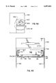
FIG. 5A is a cross-section side view of a computer illustrating a preferred arrangement of cables for use with the invention.
FIG. 5B is the computer of FIG. 5A, illustrating two removed bezels and a peripheral device ready for insertion.
FIG. 5C is the computer of FIGS. 5A and 5B with a newly installed peripheral device.
DETAILED DESCRIPTION OF THE PREFERRED EMBODIMENT OF THE INVENTION
FIG. 1 illustrates an example embodiment of a carrier in accordance with the invention. In the embodiment illustrated in FIG. 1, a carrier 100 has a tray 102 and a cam plate 104. Cam plate 104 is shown separately in FIG. 2. In FIG. 1, the tray 102 includes four tabs 106, each tab having a portion that is bent at ninety degrees, for attaching a computer peripheral device to the tray (using screws). Each tab extends through a tab slot 108 in the cam plate 104. Each tab slot 108 has a wide portion 110 that permits the bent tabs 106 to pass through the cam plate 104 for assembly. The wide portion 110 also provides access for a screwdriver to enable attachment of the peripheral device to the tabs 106 after the tabs 106 have been passed through the cam plate 104. The carrier 100 also includes brackets 112 mounted on each side of the tray. The brackets 112 are shown separately in FIG. 3. In FIG. 1, each bracket 112 is hinged at the top via a simple slot and tab arrangement, and each bracket has a tab 114, extending into a cam slot 116 in the cam plate 104. The carrier 100 also includes elastomeric (compressible) pads 118, each pad 118 attached to a bracket 112. Preferably, there are at least two pads on each side of the carrier.
Computers typically have a metal chassis or drive bay that has rigid sides for attaching a peripheral device (using screws). Computers typically have a peripheral device bay that is covered by removable plastic bezels. When a peripheral device is installed, a plastic bezel is removed from the computer case, and the newly installed device typically includes a plastic cosmetic bezel that fits in the location where a computer bezel was earlier removed.
In operation, the carrier 100 is inserted into the drive bay of a computer, with the cam plate 104 initially extending beyond the front bezel of the attached peripheral device. When the front bezel of the peripheral device is flush with the computer housing, the cam plate 104 is pushed into the tray 102 until the cam plate is flush with the front bezel of the peripheral device. When the cam plate 104 is pushed inward, the cam slots 116 on the cam plate force the tabs 114 on the brackets 112 outward, forcing the elastomeric pads 118 against the sides of the drive bay of the computer. The peripheral device is then clamped in place by the force of the elastomeric pads against the sides of the drive bay of the computer. For removal, the cam plate 104 is pulled out from the tray 102, releasing the force on the elastomeric pads 118, and freeing the carrier and the peripheral device for removal.
FIG. 3 further illustrates the brackets 112 and elastomeric pads 118. In FIG. 3, a simple slot 300 is used for a hinge arrangement with a matching tab on the side of the tray. Preferably, the brackets and elastomeric pads include a serrated metal portion 302 that is conductively connected to the bracket and thus to the tray. When the elastomeric pads 118 make initial contact with the computer housing, the serrated metal portion 302 is not in contact. As the elastomeric pads are compressed, the serrated metal portions 302 contact the side walls of the computer housing to provide grounding and electrostatic discharge protection. If for some reason the computer chassis does not provide a ground potential, a ground wire to the peripheral device may be required in addition to the standard power and signal cables.
FIG. 4A illustrates a computer 400 having a peripheral device bay 402 capable of holding up to four peripheral devices of a standard height. One peripheral device 404 is installed with an attached bezel. A second peripheral device has been attached in the drive bay in a second peripheral device slot 406 in accordance with the invention. As illustrated in further detail in FIG. 4B, a peripheral device 408 is attached to the carrier 100, which in turn is clamped against side walls 410 and 412 of the computer peripheral device bay. Note in particular that the elastomeric pads 118 have been compressed sufficient to enable the serrated metal portions 302 to contact side walls 410 and 412.
One goal of the present invention is to provide a carrier that works with commonly available peripheral device bays, without requiring any special adapters or connectors in the host computer. Accordingly, a carrier in accordance with the invention preferably does not include an electrical connector attached to the carrier for connecting to a mating connector in the computer. Instead, the peripheral device being installed comes with an adapter cable. Unattached cables (for example, power and signal cables) within the computer are temporarily secured in a spot that is easily accessible when a bezel is removed from the peripheral device bay of the computer. For example, the cables may be secured to a removable bezel using a spring clip. Alternatively, the cables may be simply taped to one of the walls of the peripheral device bay. The only requirement is that the unattached cables should be readily accessible when a bezel is removed from the peripheral device bay.
FIG. 5A illustrates a computer peripheral device bay with an unattached internal cable 500 secured to a bezel 502 covering an empty device slot. An additional empty device slot is covered by a bezel 504. When a peripheral device is installed in accordance with the invention, two computer bezels are removed (if an additional peripheral device slot in the computer is available). In the computer illustrated in FIG. 5A, two device slots are available, so bezels 502 and 504 are both removed, as illustrated in FIG. 5B. Bezel 502 may then be discarded. As illustrated in FIG. 5B, the unattached cable 500 internal to the computer is attached to an adapter cable 506 and the adapter cable 506 is attached to a peripheral device 508. The adapter cable 506 has a unattached part 510 that is secured (for example, taped) in an empty peripheral device slot or to the second computer bezel 504 (for example, taped or clipped). As illustrated in FIG. 5C, when the peripheral device 508 is inserted into the computer, the cable 500 from inside the computer is carried into the computer. The second computer bezel 504 is reattached to the computer. The unattached part 510 of adapter cable 506 is readily accessible for installation of an additional peripheral device in the empty peripheral device slot. If the computer does not have any empty peripheral device slots, the computer cable 500 may be attached directly to the peripheral device 508 and the adapter cable 506 may be discarded. Note that for simplicity of illustration, cable 500 in FIGS. 5A-5C is illustrated as a single cable. Typically, peripheral devices require a separate power cable, a separate signal cable, and sometimes additional cables such as audio cables. Cable 500 depicts all required cables in one bundle.
For most computers, the present invention does not require any modification to the metal parts of the computer chassis or drive bay that are intended for attachment of a peripheral device. The only requirement is that the computer chassis must have two rigid sidewalls for supporting the peripheral device. In addition, internal computer cables are preferably secured in an empty peripheral device bay for easy accessibility.
The present invention is particularly applicable to computer peripheral devices, but may be equally applicable to any modular device bays for electronic equipment, including for example, racks for electronic audio and video equipment, and electronic instrumentation racks. The carrier could also be used, for example, for a removable audio system in an automobile.
The foregoing description of the present invention has been presented for purposes of illustration and description. It is not intended to be exhaustive or to limit the invention to the precise form disclosed, and other modifications and variations may be possible in light of the above teachings. The embodiment was chosen and described in order to best explain the principles of the invention and its practical application to thereby enable others skilled in the art to best utilize the invention in various embodiments and various modifications as are suited to the particular use contemplated. It is intended that the appended claims be construed to include other alternative embodiments of the invention except insofar as limited by the prior art.

Claims (3)

What is claimed is:
1. A carrier for an electronic device to be installed into an enclosure, the enclosure having rigid walls for attachment of electronic devices, the carrier comprising:
a tray, having two opposing sides, the electronic device attached to the tray;
at least two pads that are compressible, positioned at the sides of the tray;
an actuator, moveable relative to the tray, the actuator including cam surfaces contacting the pads; and
when the carrier is positioned within the enclosure, movement of the actuator relative to the tray causes the cam surfaces to force the pads outward from the sides of the tray, compressing the pads against the rigid walls of the enclosure, thereby clamping the carrier to the enclosure.
2. The carrier of claim 1, the actuator further comprising a plate, the cam surfaces comprising slots in the plate.
3. The carrier of claim 2, further comprising:
brackets, one bracket for each pad, each bracket having a tab that travels in one of the slots in the plate, wherein movement of the plate relative to the tray causes brackets to move outward as the tabs move in the slots in the plate, each bracket in turn pushing a corresponding pad outward.
US09/219,949 1998-12-23 1998-12-23 Carrier to facilitate installation of an electronic device into an enclosure Expired - Lifetime US6097604A (en)

Priority Applications (3)

Application Number Priority Date Filing Date Title
US09/219,949 US6097604A (en) 1998-12-23 1998-12-23 Carrier to facilitate installation of an electronic device into an enclosure
EP99117257A EP1014369A3 (en) 1998-12-23 1999-09-02 Carrier to facilitate installation of an electronic device into an enclosure
JP36609199A JP3406263B2 (en) 1998-12-23 1999-12-24 Carrier to facilitate installation of electronic devices in enclosures

Applications Claiming Priority (1)

Application Number Priority Date Filing Date Title
US09/219,949 US6097604A (en) 1998-12-23 1998-12-23 Carrier to facilitate installation of an electronic device into an enclosure

Publications (1)

Publication Number Publication Date
US6097604A true US6097604A (en) 2000-08-01

Family

ID=22821401

Family Applications (1)

Application Number Title Priority Date Filing Date
US09/219,949 Expired - Lifetime US6097604A (en) 1998-12-23 1998-12-23 Carrier to facilitate installation of an electronic device into an enclosure

Country Status (3)

Country Link
US (1) US6097604A (en)
EP (1) EP1014369A3 (en)
JP (1) JP3406263B2 (en)

Cited By (13)

* Cited by examiner, † Cited by third party
Publication number Priority date Publication date Assignee Title
US20030041201A1 (en) * 2001-07-12 2003-02-27 Rauscher Tomlinson G. Raid system with multiple controllers and proof against any single point of failure
US6665166B2 (en) * 2001-03-15 2003-12-16 Hewlett-Packard Development Company, L.P. Systems with enhanced electrostatic discharge protection
US6802575B1 (en) * 2002-09-05 2004-10-12 Harry P. Lee Rack mount
US6888069B1 (en) * 2004-05-26 2005-05-03 Nortel Networks Limited Equipment tray for simplified insertion and removal of rack-mounted equipment
US20060277858A1 (en) * 2005-06-13 2006-12-14 Inventec Corporation Installing structure for modularized electronic device
US20090316349A1 (en) * 2008-06-18 2009-12-24 Sun Microsystems, Inc. Hard disk drive bracket damping mechanism
US20100002366A1 (en) * 2008-07-07 2010-01-07 Dell Products L.P. Multiple Component Mounting System
US20100276557A1 (en) * 2009-04-30 2010-11-04 HONG FU JIN PRECISION INDUSTRY (ShenZhen) CO., LTD, Fixing mechanism for storage device
US20130039014A1 (en) * 2011-08-10 2013-02-14 Hon Hai Precision Industry Co., Ltd. Mounting apparatus for data storage device
CN105221898A (en) * 2015-10-21 2016-01-06 阳玉芳 A kind of support for supporting mobile phone and panel computer
US9857851B1 (en) 2016-06-30 2018-01-02 Seagate Technology Llc Toolless data storage device carrier
US10080306B2 (en) 2016-12-15 2018-09-18 Raytheon Company Equipment clamping assembly having horizontal and vertical clamps for use in rugged and other environments
US10368459B2 (en) 2016-12-15 2019-07-30 Raytheon Company Equipment clamping assembly using clamps and friction to secure equipment for use in rugged and other environments

Families Citing this family (2)

* Cited by examiner, † Cited by third party
Publication number Priority date Publication date Assignee Title
WO2003021598A1 (en) * 2001-08-29 2003-03-13 Xyratex Technology Limited, Mounting for disk drive unit and method of handling
US7054150B2 (en) 2001-08-29 2006-05-30 Xyratex Technology Limited Mounting for disk drive unit and method of handling

Citations (13)

* Cited by examiner, † Cited by third party
Publication number Priority date Publication date Assignee Title
US4894792A (en) * 1988-09-30 1990-01-16 Tandy Corporation Portable computer with removable and replaceable add-on modules
US4941841A (en) * 1988-06-09 1990-07-17 Darden Julius C Adapter and a removable slide-in cartridge for an information storage system
US4982303A (en) * 1988-10-31 1991-01-01 Zenith Data Systems Corporation Removable hard disk drive having a combination latch, lever and handle
US5003431A (en) * 1989-12-18 1991-03-26 Unisys Corporation Insertion, extraction, and clamping apparatus for electrical modules
US5195022A (en) * 1991-11-01 1993-03-16 Hewlett-Packard Company Removable mass storage module for computer systems
US5269698A (en) * 1993-01-26 1993-12-14 Silicon Graphics, Inc. Retaining and release mechanism for computer storage devices including a pawl latch assembly
US5481431A (en) * 1994-01-28 1996-01-02 Sun Microsystems, Inc. System having U-shaped actuator and handle with cam surfaces for mounting computer hard drive or the like
US5566383A (en) * 1993-04-01 1996-10-15 Zenith Data Systems Corporation Drive platform assembly with rotatable mounting brackets and automatic grounding bracket
US5579204A (en) * 1994-08-05 1996-11-26 Emc Corporation Disk carrier assembly
US5680293A (en) * 1996-09-13 1997-10-21 Dell U.S.A., L.P. Screwless hard drive mounting in a computer system with a chassis via a first bracket rigidly mounted to the chassis and a second bracket movably mounted to the chassis
US5687059A (en) * 1994-09-07 1997-11-11 Hewlett-Packard Co Mass storage device mounting scheme
US5726922A (en) * 1994-01-03 1998-03-10 International Business Machines Corp. Assembly for removably connecting data storage devices
US5768099A (en) * 1997-01-23 1998-06-16 Dell Computer Corporation Computer with an improved disk drive mounting assembly

Family Cites Families (3)

* Cited by examiner, † Cited by third party
Publication number Priority date Publication date Assignee Title
JPS6133251U (en) * 1984-07-30 1986-02-28 ジューキ株式会社 Media loading mechanism of magnetic recording media playback device
US4896777A (en) * 1988-04-06 1990-01-30 Digital Equipment Corporation Lock and shock mounted device for computer disk drive
EP0831388B1 (en) * 1996-09-24 2003-04-09 Hewlett-Packard Company, A Delaware Corporation Computer with mounting arrangement for optional unit

Patent Citations (13)

* Cited by examiner, † Cited by third party
Publication number Priority date Publication date Assignee Title
US4941841A (en) * 1988-06-09 1990-07-17 Darden Julius C Adapter and a removable slide-in cartridge for an information storage system
US4894792A (en) * 1988-09-30 1990-01-16 Tandy Corporation Portable computer with removable and replaceable add-on modules
US4982303A (en) * 1988-10-31 1991-01-01 Zenith Data Systems Corporation Removable hard disk drive having a combination latch, lever and handle
US5003431A (en) * 1989-12-18 1991-03-26 Unisys Corporation Insertion, extraction, and clamping apparatus for electrical modules
US5195022A (en) * 1991-11-01 1993-03-16 Hewlett-Packard Company Removable mass storage module for computer systems
US5269698A (en) * 1993-01-26 1993-12-14 Silicon Graphics, Inc. Retaining and release mechanism for computer storage devices including a pawl latch assembly
US5566383A (en) * 1993-04-01 1996-10-15 Zenith Data Systems Corporation Drive platform assembly with rotatable mounting brackets and automatic grounding bracket
US5726922A (en) * 1994-01-03 1998-03-10 International Business Machines Corp. Assembly for removably connecting data storage devices
US5481431A (en) * 1994-01-28 1996-01-02 Sun Microsystems, Inc. System having U-shaped actuator and handle with cam surfaces for mounting computer hard drive or the like
US5579204A (en) * 1994-08-05 1996-11-26 Emc Corporation Disk carrier assembly
US5687059A (en) * 1994-09-07 1997-11-11 Hewlett-Packard Co Mass storage device mounting scheme
US5680293A (en) * 1996-09-13 1997-10-21 Dell U.S.A., L.P. Screwless hard drive mounting in a computer system with a chassis via a first bracket rigidly mounted to the chassis and a second bracket movably mounted to the chassis
US5768099A (en) * 1997-01-23 1998-06-16 Dell Computer Corporation Computer with an improved disk drive mounting assembly

Cited By (17)

* Cited by examiner, † Cited by third party
Publication number Priority date Publication date Assignee Title
US6665166B2 (en) * 2001-03-15 2003-12-16 Hewlett-Packard Development Company, L.P. Systems with enhanced electrostatic discharge protection
US20030041201A1 (en) * 2001-07-12 2003-02-27 Rauscher Tomlinson G. Raid system with multiple controllers and proof against any single point of failure
US6874100B2 (en) 2001-07-12 2005-03-29 Digi-Data Corporation Raid system with multiple controllers and proof against any single point of failure
US6802575B1 (en) * 2002-09-05 2004-10-12 Harry P. Lee Rack mount
US6888069B1 (en) * 2004-05-26 2005-05-03 Nortel Networks Limited Equipment tray for simplified insertion and removal of rack-mounted equipment
US20060277858A1 (en) * 2005-06-13 2006-12-14 Inventec Corporation Installing structure for modularized electronic device
US7729113B2 (en) * 2008-06-18 2010-06-01 Oracle America, Inc. Hard disk drive bracket damping mechanism
US20090316349A1 (en) * 2008-06-18 2009-12-24 Sun Microsystems, Inc. Hard disk drive bracket damping mechanism
US20100002366A1 (en) * 2008-07-07 2010-01-07 Dell Products L.P. Multiple Component Mounting System
US8045339B2 (en) * 2008-07-07 2011-10-25 Dell Products L.P. Multiple component mounting system
US20100276557A1 (en) * 2009-04-30 2010-11-04 HONG FU JIN PRECISION INDUSTRY (ShenZhen) CO., LTD, Fixing mechanism for storage device
US20130039014A1 (en) * 2011-08-10 2013-02-14 Hon Hai Precision Industry Co., Ltd. Mounting apparatus for data storage device
US8830671B2 (en) * 2011-08-10 2014-09-09 Hong Fu Jin Precision Industry (Wuhan) Co., Ltd. Mounting apparatus for data storage device
CN105221898A (en) * 2015-10-21 2016-01-06 阳玉芳 A kind of support for supporting mobile phone and panel computer
US9857851B1 (en) 2016-06-30 2018-01-02 Seagate Technology Llc Toolless data storage device carrier
US10080306B2 (en) 2016-12-15 2018-09-18 Raytheon Company Equipment clamping assembly having horizontal and vertical clamps for use in rugged and other environments
US10368459B2 (en) 2016-12-15 2019-07-30 Raytheon Company Equipment clamping assembly using clamps and friction to secure equipment for use in rugged and other environments

Also Published As

Publication number Publication date
EP1014369A3 (en) 2001-01-10
JP3406263B2 (en) 2003-05-12
JP2000196252A (en) 2000-07-14
EP1014369A2 (en) 2000-06-28

Similar Documents

Publication Publication Date Title
US6097604A (en) Carrier to facilitate installation of an electronic device into an enclosure
US5195022A (en) Removable mass storage module for computer systems
US6790066B1 (en) Apparatus for securing a cable assembly within an enclosed electronic system
US6094342A (en) Disk drive jacket
CA2328231C (en) Circuit card insertion and removal system
US5949644A (en) Computer system capable of easily extending functions
US5706179A (en) Computer housing and expansion card format for consumer electronics devices
US5654873A (en) Single connector attachment drive sled assembly having light pipe coupled to a rail
US5544008A (en) Computer expansion module apparatus
US6560114B2 (en) Rack-mounted server and associated methods
US6130817A (en) Holding system for electronic modules
US4926291A (en) Data storage mounting assembly
JP2514237B2 (en) Electronic equipment
JP3708566B2 (en) Enclosure device for disk drive
US7106581B2 (en) Modular logic board chassis for a desktop computer
US5174762A (en) Circuit board adapter for computer system
JP3412681B2 (en) Tower computer housing
US5967845A (en) Card connector assembly
US5650910A (en) Backbone substrate for a computer
US5205758A (en) Communications distribution interface unit assembly
US7040491B1 (en) Techniques for managing a set of cables
JP3822980B2 (en) Fixing plate for cable-card connector
EP1451913A1 (en) Apparatus and method for using a backshell
US5383096A (en) I/O expansion box
GB2371411A (en) Circuit board mount

Legal Events

Date Code Title Description
AS Assignment

Owner name: HEWLETT-PACKARD COMPANY, CALIFORNIA

Free format text: ASSIGNMENT OF ASSIGNORS INTEREST;ASSIGNORS:HUNTER, CHARLES L.;TAUGHER, LAWRENCE N.;REEL/FRAME:010025/0038

Effective date: 19990301

STCF Information on status: patent grant

Free format text: PATENTED CASE

FEPP Fee payment procedure

Free format text: PAYOR NUMBER ASSIGNED (ORIGINAL EVENT CODE: ASPN); ENTITY STATUS OF PATENT OWNER: LARGE ENTITY

FPAY Fee payment

Year of fee payment: 4

FPAY Fee payment

Year of fee payment: 8

REMI Maintenance fee reminder mailed
AS Assignment

Owner name: HEWLETT-PACKARD DEVELOPMENT COMPANY, L.P., TEXAS

Free format text: ASSIGNMENT OF ASSIGNORS INTEREST;ASSIGNOR:HEWLETT-PACKARD COMPANY;REEL/FRAME:026945/0699

Effective date: 20030131

FPAY Fee payment

Year of fee payment: 12