US6098448A - In situ measurement apparatus and method of measuring soil permeability and fluid flow - Google Patents
In situ measurement apparatus and method of measuring soil permeability and fluid flow Download PDFInfo
- Publication number
- US6098448A US6098448A US09/061,078 US6107898A US6098448A US 6098448 A US6098448 A US 6098448A US 6107898 A US6107898 A US 6107898A US 6098448 A US6098448 A US 6098448A
- Authority
- US
- United States
- Prior art keywords
- pressure information
- soil
- rod
- fluid
- measurement
- Prior art date
- Legal status (The legal status is an assumption and is not a legal conclusion. Google has not performed a legal analysis and makes no representation as to the accuracy of the status listed.)
- Expired - Fee Related
Links
Images


Classifications
-
- G—PHYSICS
- G01—MEASURING; TESTING
- G01N—INVESTIGATING OR ANALYSING MATERIALS BY DETERMINING THEIR CHEMICAL OR PHYSICAL PROPERTIES
- G01N15/00—Investigating characteristics of particles; Investigating permeability, pore-volume, or surface-area of porous materials
- G01N15/08—Investigating permeability, pore-volume, or surface area of porous materials
- G01N15/082—Investigating permeability by forcing a fluid through a sample
- G01N15/0826—Investigating permeability by forcing a fluid through a sample and measuring fluid flow rate, i.e. permeation rate or pressure change
Definitions
- the present invention relates to a soil characterization apparatus and method for using the same, and more particularly, to a characterization apparatus, and a method to employ such apparatus, which is adapted for use with cone penetrometer rods and other direct push emplacement technologies, for subsurface contaminant plume and landfill measurement testing.
- the permeability of soil is defined as the soil's conductivity to fluid flow.
- the permeability of soil to fluid flow depends upon the magnitude of soil gas and groundwater flow when subjected to particular natural and/or unnatural pressure gradients.
- Pressure gradients exist due to natural effects such as hydraulic gradients (in the case of groundwater) and barometrically imposed gradients (in the case of soil gas).
- Unnatural (forced) gradients can be imposed by soil vapor extraction, air sparging, active venting, pump and treat, and other remediation processes requiring the movement of fluids through the soil.
- the design of any of these processes requires a knowledge of the flow characteristics of the soil to be remediated.
- the soil's permeability is the largest variable, which can vary by orders of magnitude in any given hydrological and/or geological environment. Therefore, knowledge of soil gas permeability is required to design soil vapor extraction systems and understand, in general, the movement of gas in the soil. Similarly, knowledge of saturated hydraulic conductivity (or, the soil's permeability to liquid flow) is required to predict movement of groundwater in saturated soils.
- Soil permeability has historically been measured either in laboratories on a very small scale or in the field on a very large scale. Laboratory measurements rarely agree with data collected in the field due to the difficulty of obtaining truly undisturbed soil samples. Further, laboratory test results are usually at least an order of magnitude lower than actual field results.
- soil gas permeability measurements are obtained either through total borehole flow or isolated packer (also referred to as a "straddle packer”) measurement techniques.
- Total borehole flow measurements are obtained from open or screened boreholes, where gas or liquid is injected into or extracted from the borehole well.
- permeability measurements gas or liquid
- permeability measurements are typically obtained from boreholes using a cylindrical flow model and geometry. Long screened or uncased sections of the borehole are subjected to unnatural (e.g., forced) pressure gradients and the resultant flow into or out of the well is subsequently measured in order to obtain the soil permeability.
- test region is relatively long and a radius of influence is either measured (or can be predicted) to determine the surrounding soil's permeability.
- the inherent weakness with this approach is that it results in providing only an average permeability over the test region, and cannot delineate stratigraphic features within any particular test region or depth.
- a disadvantage to the current method of obtaining permeability measurements in the field is that it is impossible to translate unmodified open borehole measurement techniques to penetrometer measurement because of size limitations and the penetrometer's compaction of the soil.
- each penetrometer rod is a continuously cylindrical steel tube having a hollow interior channel.
- a cone-shaped tip is placed at one end of some penetrometer rods (e.g., the end which is embedded in the ground).
- these types of penetrometers are referred to as “cone penetrometers.” If desired, the penetrometer rod can travel deeply into the subsurface by the assistance of a hydraulic ram or other conventional means.
- Penetrometers provide vastly more data in the same amount of time as do drilled holes, at a much lower cost and risk to the operators of penetrometer.
- Penetrometers, and other direct push techniques are rapidly advancing as hole formation and soil characterization tools because they are capable of emplacement in difficult media. Therefore, conducting permeability measurements with direct push techniques, instead of in drilled boreholes, retains all of the advantages of penetrometer emplacements.
- conducting cone penetrometer testing using a spherical flow model can provide detailed soil permeability data as a function of the depth at which the measurement is taken. This is because the testing region is relatively small (measured in fractions of a meter versus meters for the cylindrical model), allowing discrete measurements at high resolution in boreholes.
- a method for discrete soil gas and saturated liquid permeability measurements with direct push emplacement systems (such as a cone penetrometer).
- a modified direct push emplacement system having at least one injection port and at least one monitoring port is first engaged to penetrate the soil to a predetermined depth. Gas or liquid is then injected into the soil at a predetermined location on the penetrometer rod. Next, a differential pressure response is recorded from at least two measurement ports, which are at a known distance from the injection port (on the same penetrometer rod). This pressure response data allows calculation of the soil permeability directly by using a one-dimensional, spherical, steady state, porous flow model to measure the effective permeability of the soil, without substantial disturbance of the surrounding soil.
- the present invention is well-suited to direct push applications for a number of reasons.
- Second, the present method does not require a long time period to reach a steady state condition. This provides for obtaining multiple measurements in relatively short periods of time while providing high spatial resolution.
- Third, the present invention's methodology is designed such that the compaction of soil adjacent to the rod, caused by the direct push system, has minimal impact on the inferred soil permeability.
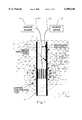
- FIG. 1 is a partial cross sectional view of the present invention inserted into the subsurface
- FIG. 2 is a graphical representation of the fluid flow field when the present invention is employed
- FIG. 3 is a partial cross sectional view of the present invention.
- FIG. 4 is a partial cross sectional view of the present invention as tested in the laboratory
- FIG. 5 is a graphical illustration of the gas pressure distribution adjacent to the test set up according to FIG. 4;
- FIG. 6 is a graphical illustration of the pressure profiles along and perpendicular to the axis of a penetrometer rod as set up according to the configuration of FIG. 4;
- FIG. 7 is an alternate embodiment of the present invention.
- FIG. 8 is a side view of an alternate embodiment of the present invention.
- FIG. 9 is a detailed view of a portion of the embodiment shown in FIG. 8;
- FIG. 10 graphically illustrates the portable vehicle employed with the invention of FIG. 8;
- FIG. 11 is another side view of the invention illustrated in FIG. 8, depicting additional components disclosed.
- FIG. 12 illustrates the one dimensional steady state, spherical porous flow model disclosed in the present invention.
- the present invention includes a hollow-channeled penetrometer rod 10 having a cone 11 at one end (as seen in FIG. 3), at least one or more injection ports 13 and a plurality of measurement ports 15 along the length of rod 10, both ports integrally formed into or upon rod 10.
- cone 11 on rod 10 is preferably of similar diameter as the diameter of rod 10.
- Each pressure port is in gas-flow communication with pressure sensor 23 through the hollow interior channel 17 of rod 10 and each port is formed at a predetermined radial distance away from any other port.
- each injection port 13 is at least equal to one half of the diameter of rod 10 to induce constant soil pressure in the adjacent environment.
- each injection port 13 is screened or slotted, is designed to allow air or fluid injection or extraction through the screened or slotted section, and is designed to assist the surrounding soil to reach equilibrium in a short time when subjected to fluid pressure.
- measurement ports 15 would be fabricated at at least two locations above the extraction zone. These ports would be filtered penetrations into the probe which would allow pressure communication up to the ground surface.
- each injection port 13 is adapted to engage one end of a conventional injection line 21a through which either gas or liquid can flow. The exterior length of injection lines 21a is then placed within the interior channel 17 of rod 10, with the injection line's second end terminating at pressure source 21 above the surface to supply gas or liquid to injection port 13.
- the plurality of measurement ports 15 are adapted to retain one or more sensor means 15a (as seen in FIG. 1) which are electrically or hydraulically connected via signal communication means 23a within the rod's interior channel 17 to one or more predetermined sensing devices 23 located above the surface.
- sensor means 15a as seen in FIG. 1
- Such sensing devices can include a wire, a conventional manometer, or a computer, all adapted to electrically communicate with the sensor means and being capable of receiving soil permeability measurement data.
- rod 10 is inserted (or, pushed) into the ground by any conventional means.
- the interior channel 17 of rod 10 will contain the necessary injection lines and electrical signal wires which connect to the injection ports and measurement ports, respectively.
- the rod's 10 exterior surface 25 will have a tight fit above and below the injection ports and measurement ports.
- a fluid such as a liquid or a gas, is injected through injection line 21a (or extracted from the injection line) to an injection port 13 on the penetrometer rod 10.
- This injection (or extraction) will result in a spherical flow field as the fluid moves outward from the rod, and is required to induce an equilibrium in the surrounding soil for accuracy. In most circumstances, soil equilibrium is achieved in less than five minutes. Subsequently, the flow field will become essentially spherical even if the soil adjacent to the rod is of a much lower permeability (due to soil compaction).
- the injection or extraction source is represented as a spherical volume with radius r o . Fluid is added (or removed) from the zone at a known rate.
- the medium has a permeability, k, which is assumed homogeneous.
- the permeability test data results may be heavily influenced by the compacted soil annulus formed as penetrometer 10 is forced into the adjacent soil.
- a compacted layer as thin as half a centimeter would likely result in artificially low inferred permeability due to the high pressure gradient caused in this region by the reduction of soil porosity.
- the pressure field will eventually become spherical as the distance from the injection zone increases.
- the details of the extraction source geometry can be ignored if radial pressure measurements are taken at a distance from the source.
- the resulting radial pressure profile then allows the definition of r o as the distance from the extraction source to the first pressure measurement location (as seen in FIG. 2).
- FIGS. 4 and 6 exemplify a laboratory test simulation where the steady state radial symmetric AIRFLOW code was used to model the soil gas response.
- a 4.4 cm-diameter penetrometer with a 32 cm-high screened injection zone is emplaced in soil with a uniform permeability of 5 Darcies.
- the resulting contour plot indicates that at a short distance from the extraction source, the isobars become very spherical.
- the cylindrical geometry eventually results in a spherical flow field.
- the pressure profile along the axis of the penetrometer equals the profile radially outward from the penetrometer rod.
- a one dimensional steady state flow model is employed to generate the desired information.
- R is the universal gas constant
- P o is the pressure inside the sphere
- P is the pressure outside of the sphere
- r o is the radius within the sphere
- r is the radius outside of the sphere
- ⁇ is the density
- ⁇ is the viscosity of the injection fluid
- T is the temperature
- m is the fluid's flow rate.
- an alternative embodiment of the present invention is adapted to obtain permeability measurements using inflatable packers inside of the rod.
- miniature packers 35 are secured along the penetrometer rod at preselected intervals.
- Each packer 35 is capable of being inflated, so that when rod 10 is at the desired subsurface depth, all the packers are inflated to provide a stable support structure for the rod and also provide a plurality of enclosed testing regions 50.
- Each testing region 50 includes a port 15 which allows fluid pressure communication with the soil.
- the packer 35 allows injection of air into the soil while the pressure measurements accurately monitor soil gas pressure. This design has the advantage of leaving the penetrometer rod open for other uses. In operation, each testing region 50 can either be an injection port 13 or a measurement port 15.
- FIGS. 8-11 An alternate embodiment of the present invention is shown in FIGS. 8-11.
- a direct push emplacement system is mounted on a truck for portability.
- the system includes rod 51 similar to rod 10 above, and preferably, is a conventional two inch diameter by approximately three foot long length.
- the internal channel of rod 51 includes tubing 67 which can transport fluid from the earthen surface to the point of desired injection (defined as the injection zone). Gas (such as air) or liquid (such as water) is injected into the soil through a screened or filtered portion 53 located at the bottom of rod 51.
- Rod 51 includes a plurality of precision pressure sensors 55 (preferably five) embedded in rod 51 to measure the pore fluid pressure in the soil at specific distances from the injection zone.
- the electrical signals generated from sensors 55 are then transmitted to the earthen surface to a data acquisition unit 57 (such as a computer) by conventional means, such as electrical wire or cable 59.
- a data acquisition unit 57 such as a computer
- conventional means such as electrical wire or cable 59.
- the fluid injection zone pressure and temperature inside rod 51 are measured with sensors 61.
- the information generated by sensors 61 is transmitted to the earthen surface through conventional means, such as cable 59.
- the alternate embodiment is employed by stationing truck 63 over a preselected measurement location 65.
- Penetrometer rod is pushed to the desired measurement depth 65.
- Gas or fluid is then pumped into the injection tubing 67 from box 69 containing the gas and fluid pumps.
- a reservoir of clean water 71 (or similar fluid) can be used to provide the injection fluid.
- pump box 69 also includes meters (not shown) that measure the gas and fluid flow rates. Signals from these flow meters, and pressure sensors 55, 61 in the rod section, can then be transmitted to data acquisition unit and analysis device 57 through cable 59.
- Data acquisition unit and analysis device 57 calculates the permeability using mathematical models described above.
- the advantage of the present invention is that it provides higher quality data and will work over long distances (e.g., hundreds of feet). In contrast, the previous methods are difficult to employ using long pressure measurement tubes.
- the present invention offers several advantages over conventional soil permeability techniques.
- the present invention provides an absolute measure of soil permeability and is adapted to measure a wide range of soil permeability conditions in both saturated and unsaturated soil.
- the invention also does not require permanently occupying the inner core of the penetrometer and is designed to pass other electrical signals and tubes running to measurements at the penetrometer's tip.
- the cost savings of this method when compared to drilled borehole measurements, are significant. Borehole formation costs range from tens to hundreds of thousands of dollars for a typical well, depending on the type of drilling operation, nature of contamination, depth of well, and the geologic media. Additionally, a typical drilling operation for a 100 ft. well requires two to five days.
- the method of the present invention can be accomplished in one day with a full suite of measurements.
- the measurement time per station is less than five minutes, so 20 to 40 measurements could be accomplished during one push, in one day. This provides a great deal of detail in permeability distribution.
Abstract
Description
Claims (28)
Priority Applications (1)
| Application Number | Priority Date | Filing Date | Title |
|---|---|---|---|
| US09/061,078 US6098448A (en) | 1998-04-15 | 1998-04-15 | In situ measurement apparatus and method of measuring soil permeability and fluid flow |
Applications Claiming Priority (1)
| Application Number | Priority Date | Filing Date | Title |
|---|---|---|---|
| US09/061,078 US6098448A (en) | 1998-04-15 | 1998-04-15 | In situ measurement apparatus and method of measuring soil permeability and fluid flow |
Publications (1)
| Publication Number | Publication Date |
|---|---|
| US6098448A true US6098448A (en) | 2000-08-08 |
Family
ID=22033467
Family Applications (1)
| Application Number | Title | Priority Date | Filing Date |
|---|---|---|---|
| US09/061,078 Expired - Fee Related US6098448A (en) | 1998-04-15 | 1998-04-15 | In situ measurement apparatus and method of measuring soil permeability and fluid flow |
Country Status (1)
| Country | Link |
|---|---|
| US (1) | US6098448A (en) |
Cited By (29)
| Publication number | Priority date | Publication date | Assignee | Title |
|---|---|---|---|---|
| US6451210B1 (en) | 2000-11-20 | 2002-09-17 | General Electric Company | Method and system to remotely monitor a carbon adsorption process |
| US6453727B1 (en) * | 2000-06-23 | 2002-09-24 | Institut Francais Du Petrole | Method of evaluating physical parameters of an underground reservoir from rock cuttings taken therefrom |
| US6491828B1 (en) | 2000-11-07 | 2002-12-10 | General Electric Company | Method and system to remotely monitor groundwater treatment |
| US6571605B2 (en) * | 2001-01-19 | 2003-06-03 | Larry Keith Johnson | Constant-head soil permeameter for determining the hydraulic conductivity of earthen materials |
| US6611760B2 (en) * | 2001-12-14 | 2003-08-26 | Hydro Geo Chem, Inc. | Method and system for estimating gas production by a landfill or other subsurface source |
| US6615653B1 (en) * | 2001-09-27 | 2003-09-09 | Geosierra, Llc | In situ method for determining soil liquefaction tendency and its prevention by electro-osmosis |
| US6644423B2 (en) * | 2000-07-27 | 2003-11-11 | Applied Research Associates, Inc. | Wireline system for multiple direct push tool usage |
| US20030217588A1 (en) * | 2002-05-23 | 2003-11-27 | Marc Jalbert | Handheld device for intrusive and non-intrusive field measurements of air permeability of soil |
| US6810755B1 (en) * | 2001-12-11 | 2004-11-02 | West Virginia University | Permeameter system and method to determine soil hydraulic capacity for onsite wastewater systems |
| US20050103101A1 (en) * | 2001-12-20 | 2005-05-19 | Martin Power | Percolation test apparatus |
| US20050177309A1 (en) * | 2002-05-13 | 2005-08-11 | Ramanathan Sri Ranjan | Method and probe for measuring hydraulic conductivity of soil |
| US20060046297A1 (en) * | 2004-08-31 | 2006-03-02 | Ball Raymond G | In situ remedial alternative and aquifer properties evaluation probe system |
| US20090266154A1 (en) * | 2006-06-10 | 2009-10-29 | Intelisys Limited | In-borehole gas monitor apparatus and method |
| US20110313685A1 (en) * | 2008-12-31 | 2011-12-22 | Koen Geirnaert | System and method for sand detection |
| CN102466532A (en) * | 2010-11-11 | 2012-05-23 | 中国石油天然气股份有限公司 | Method and device for testing gas seepage starting pressure in core |
| CN101968423B (en) * | 2009-07-27 | 2012-07-18 | 中国石油天然气股份有限公司 | Low-permeability reservoir bed starting pressure testing method |
| CN102680352A (en) * | 2012-05-10 | 2012-09-19 | 张振华 | Transient state measurement system and method for air guide rate of frozen soil |
| CN102680351A (en) * | 2012-05-10 | 2012-09-19 | 张振华 | Steady-state measurement system and method for air guide rate of frozen soil |
| WO2013082899A1 (en) * | 2011-12-06 | 2013-06-13 | 鲁东大学 | Soil air-permeability measuring apparatus |
| US9366560B2 (en) | 2013-08-01 | 2016-06-14 | John Cacciola | Detector for detecting a change in a fluid level and generating a digital signal |
| US20160209309A1 (en) * | 2013-09-03 | 2016-07-21 | Dotocean Nv | Sediment sounding pole and handheld density profiler |
| CN106290077A (en) * | 2016-11-04 | 2017-01-04 | 西南交通大学 | The full water stratum face soil body is in three-dimensional stress lower critical infiltration pressure testing device and test method |
| CN106769786A (en) * | 2017-02-16 | 2017-05-31 | 河海大学 | A kind of portable coarse-grained soil original position permeability test method |
| WO2017222372A1 (en) * | 2016-06-20 | 2017-12-28 | Fugro N.V. | A method, a system, and a computer program product for determining soil properties |
| US20180252629A1 (en) * | 2015-10-19 | 2018-09-06 | Hz-Dr. Hans Jürgen Hahn Und Dr. Thomas Zumbroich Gbr | Substrate permeability measuring device |
| CN109269955A (en) * | 2018-09-29 | 2019-01-25 | 中国矿业大学 | A kind of coal rock layer permeability in-situ testing device and method |
| CN109444021A (en) * | 2018-12-18 | 2019-03-08 | 敦煌研究院 | A kind of device for monitoring, measuring the gas permeability of soil |
| CN113447635A (en) * | 2021-05-11 | 2021-09-28 | 江西农业大学 | Device for measuring release rate of greenhouse gases in different depths of potted soil |
| CN114136856A (en) * | 2021-08-27 | 2022-03-04 | 中国人民解放军63653部队 | Permeability in-situ measuring device for particle accumulation type medium and measuring method thereof |
Citations (10)
| Publication number | Priority date | Publication date | Assignee | Title |
|---|---|---|---|---|
| US2210546A (en) * | 1938-02-14 | 1940-08-06 | Shell Dev | Soil gas sampling device and method |
| US2979134A (en) * | 1955-05-20 | 1961-04-11 | Phillips Petroleum Co | Core hole testing apparatus |
| US3181608A (en) * | 1961-08-11 | 1965-05-04 | Shell Oil Co | Method for determining permeability alignment in a formation |
| US3871218A (en) * | 1972-08-25 | 1975-03-18 | Anvar | Method and apparatus for determining the permeability characteristics of a porous or fissured medium |
| US4742459A (en) * | 1986-09-29 | 1988-05-03 | Schlumber Technology Corp. | Method and apparatus for determining hydraulic properties of formations surrounding a borehole |
| US4936139A (en) * | 1988-09-23 | 1990-06-26 | Schlumberger Technology Corporation | Down hole method for determination of formation properties |
| US5465628A (en) * | 1992-09-22 | 1995-11-14 | Timmons; Robert D. | Multiple sampling lysimeter |
| US5548991A (en) * | 1995-03-09 | 1996-08-27 | Ritson; Marc J. | Permeameter probe |
| US5698799A (en) * | 1996-06-07 | 1997-12-16 | Lee, Jr.; Landris T. | Zone isolator module for use on a penetrometer |
| US5744730A (en) * | 1997-02-14 | 1998-04-28 | Ballard; John H. | Subsurface in-situ radon gas detection/penetrometer system |
-
1998
- 1998-04-15 US US09/061,078 patent/US6098448A/en not_active Expired - Fee Related
Patent Citations (10)
| Publication number | Priority date | Publication date | Assignee | Title |
|---|---|---|---|---|
| US2210546A (en) * | 1938-02-14 | 1940-08-06 | Shell Dev | Soil gas sampling device and method |
| US2979134A (en) * | 1955-05-20 | 1961-04-11 | Phillips Petroleum Co | Core hole testing apparatus |
| US3181608A (en) * | 1961-08-11 | 1965-05-04 | Shell Oil Co | Method for determining permeability alignment in a formation |
| US3871218A (en) * | 1972-08-25 | 1975-03-18 | Anvar | Method and apparatus for determining the permeability characteristics of a porous or fissured medium |
| US4742459A (en) * | 1986-09-29 | 1988-05-03 | Schlumber Technology Corp. | Method and apparatus for determining hydraulic properties of formations surrounding a borehole |
| US4936139A (en) * | 1988-09-23 | 1990-06-26 | Schlumberger Technology Corporation | Down hole method for determination of formation properties |
| US5465628A (en) * | 1992-09-22 | 1995-11-14 | Timmons; Robert D. | Multiple sampling lysimeter |
| US5548991A (en) * | 1995-03-09 | 1996-08-27 | Ritson; Marc J. | Permeameter probe |
| US5698799A (en) * | 1996-06-07 | 1997-12-16 | Lee, Jr.; Landris T. | Zone isolator module for use on a penetrometer |
| US5744730A (en) * | 1997-02-14 | 1998-04-28 | Ballard; John H. | Subsurface in-situ radon gas detection/penetrometer system |
Cited By (46)
| Publication number | Priority date | Publication date | Assignee | Title |
|---|---|---|---|---|
| US6453727B1 (en) * | 2000-06-23 | 2002-09-24 | Institut Francais Du Petrole | Method of evaluating physical parameters of an underground reservoir from rock cuttings taken therefrom |
| US6644423B2 (en) * | 2000-07-27 | 2003-11-11 | Applied Research Associates, Inc. | Wireline system for multiple direct push tool usage |
| US6491828B1 (en) | 2000-11-07 | 2002-12-10 | General Electric Company | Method and system to remotely monitor groundwater treatment |
| US6451210B1 (en) | 2000-11-20 | 2002-09-17 | General Electric Company | Method and system to remotely monitor a carbon adsorption process |
| US6571605B2 (en) * | 2001-01-19 | 2003-06-03 | Larry Keith Johnson | Constant-head soil permeameter for determining the hydraulic conductivity of earthen materials |
| US6938461B1 (en) | 2001-01-19 | 2005-09-06 | Larry K. Johnson | Constant-head soil permeameter for determining the hydraulic conductivity of earthen materials at a wide range of depths |
| US6615653B1 (en) * | 2001-09-27 | 2003-09-09 | Geosierra, Llc | In situ method for determining soil liquefaction tendency and its prevention by electro-osmosis |
| US6810755B1 (en) * | 2001-12-11 | 2004-11-02 | West Virginia University | Permeameter system and method to determine soil hydraulic capacity for onsite wastewater systems |
| US6611760B2 (en) * | 2001-12-14 | 2003-08-26 | Hydro Geo Chem, Inc. | Method and system for estimating gas production by a landfill or other subsurface source |
| US20050103101A1 (en) * | 2001-12-20 | 2005-05-19 | Martin Power | Percolation test apparatus |
| US7062957B2 (en) * | 2001-12-20 | 2006-06-20 | Arcaid International Limitged | Percolation test apparatus |
| US20050177309A1 (en) * | 2002-05-13 | 2005-08-11 | Ramanathan Sri Ranjan | Method and probe for measuring hydraulic conductivity of soil |
| US7059174B2 (en) * | 2002-05-13 | 2006-06-13 | Ramanathan Sri Ranjan | Method and probe for measuring hydraulic conductivity of soil |
| US20030217588A1 (en) * | 2002-05-23 | 2003-11-27 | Marc Jalbert | Handheld device for intrusive and non-intrusive field measurements of air permeability of soil |
| US20060046297A1 (en) * | 2004-08-31 | 2006-03-02 | Ball Raymond G | In situ remedial alternative and aquifer properties evaluation probe system |
| US20090324337A1 (en) * | 2004-08-31 | 2009-12-31 | Enchem Engineering, Inc. | In Situ Remedial Alternative and Aquifer Properties Evaluation Probe System |
| US7659123B2 (en) * | 2004-08-31 | 2010-02-09 | Enchem Engineering, Inc. | In situ remedial alternative and aquifer properties evaluation probe system |
| US20090266154A1 (en) * | 2006-06-10 | 2009-10-29 | Intelisys Limited | In-borehole gas monitor apparatus and method |
| US8186211B2 (en) * | 2006-06-10 | 2012-05-29 | Intelisys Limited | In-borehole gas monitor apparatus and method |
| US20110313685A1 (en) * | 2008-12-31 | 2011-12-22 | Koen Geirnaert | System and method for sand detection |
| CN101968423B (en) * | 2009-07-27 | 2012-07-18 | 中国石油天然气股份有限公司 | Low-permeability reservoir bed starting pressure testing method |
| CN102466532A (en) * | 2010-11-11 | 2012-05-23 | 中国石油天然气股份有限公司 | Method and device for testing gas seepage starting pressure in core |
| CN102466532B (en) * | 2010-11-11 | 2013-07-31 | 中国石油天然气股份有限公司 | Method and device for testing gas seepage starting pressure in core |
| WO2013082899A1 (en) * | 2011-12-06 | 2013-06-13 | 鲁东大学 | Soil air-permeability measuring apparatus |
| CN102680352A (en) * | 2012-05-10 | 2012-09-19 | 张振华 | Transient state measurement system and method for air guide rate of frozen soil |
| CN102680351A (en) * | 2012-05-10 | 2012-09-19 | 张振华 | Steady-state measurement system and method for air guide rate of frozen soil |
| US9366560B2 (en) | 2013-08-01 | 2016-06-14 | John Cacciola | Detector for detecting a change in a fluid level and generating a digital signal |
| US20160209309A1 (en) * | 2013-09-03 | 2016-07-21 | Dotocean Nv | Sediment sounding pole and handheld density profiler |
| US20180252629A1 (en) * | 2015-10-19 | 2018-09-06 | Hz-Dr. Hans Jürgen Hahn Und Dr. Thomas Zumbroich Gbr | Substrate permeability measuring device |
| US11480512B2 (en) | 2016-06-20 | 2022-10-25 | Fugro N.V. | Method, a system, and a computer program product for determining soil properties using pumping tests |
| WO2017222372A1 (en) * | 2016-06-20 | 2017-12-28 | Fugro N.V. | A method, a system, and a computer program product for determining soil properties |
| NL2017006B1 (en) * | 2016-06-20 | 2018-01-04 | Fugro N V | a method, a system, and a computer program product for determining soil properties |
| US11320358B2 (en) * | 2016-06-20 | 2022-05-03 | Fugro N.V. | Method, a system, and a computer program product for determining soil properties using pumping tests |
| EP3936669A1 (en) * | 2016-06-20 | 2022-01-12 | Fugro N.V. | A method, a system, and a computer program product for determining soil properties |
| US20190250090A1 (en) * | 2016-06-20 | 2019-08-15 | Fugro N.V. | A method, a system, and a computer program product for determining soil properties |
| CN106290077B (en) * | 2016-11-04 | 2019-11-29 | 西南交通大学 | The full water stratum face soil body permeates pressure testing device and test method in three-dimensional stress lower critical |
| CN106290077A (en) * | 2016-11-04 | 2017-01-04 | 西南交通大学 | The full water stratum face soil body is in three-dimensional stress lower critical infiltration pressure testing device and test method |
| CN106769786B (en) * | 2017-02-16 | 2019-03-22 | 河海大学 | A kind of portable coarse-grained soil original position permeability test method |
| CN106769786A (en) * | 2017-02-16 | 2017-05-31 | 河海大学 | A kind of portable coarse-grained soil original position permeability test method |
| CN109269955A (en) * | 2018-09-29 | 2019-01-25 | 中国矿业大学 | A kind of coal rock layer permeability in-situ testing device and method |
| CN109269955B (en) * | 2018-09-29 | 2023-11-21 | 中国矿业大学 | In-situ testing device and method for permeability of coal stratum |
| CN109444021A (en) * | 2018-12-18 | 2019-03-08 | 敦煌研究院 | A kind of device for monitoring, measuring the gas permeability of soil |
| CN113447635A (en) * | 2021-05-11 | 2021-09-28 | 江西农业大学 | Device for measuring release rate of greenhouse gases in different depths of potted soil |
| CN113447635B (en) * | 2021-05-11 | 2023-09-29 | 江西农业大学 | Potted plant soil greenhouse gas release rate measuring device with different depths |
| CN114136856A (en) * | 2021-08-27 | 2022-03-04 | 中国人民解放军63653部队 | Permeability in-situ measuring device for particle accumulation type medium and measuring method thereof |
| CN114136856B (en) * | 2021-08-27 | 2023-12-01 | 中国人民解放军63653部队 | In-situ permeability measurement device and method for particle stacking type medium |
Similar Documents
| Publication | Publication Date | Title |
|---|---|---|
| US6098448A (en) | In situ measurement apparatus and method of measuring soil permeability and fluid flow | |
| Quinn et al. | Using constant head step tests to determine hydraulic apertures in fractured rock | |
| US3611799A (en) | Multiple chamber earth formation fluid sampler | |
| Molz et al. | Development and application of borehole flowmeters for environmental assessment | |
| US7893692B2 (en) | Method for estimating the formation productivity from nuclear magnetic resonance measurements | |
| Meyer et al. | Characteristics of high resolution hydraulic head profiles and vertical gradients in fractured sedimentary rocks | |
| US5672819A (en) | Formation evaluation using phase shift periodic pressure pulse testing | |
| US7181960B2 (en) | Determination of correct horizontal and vertical permeabilities in a deviated well | |
| US7281435B2 (en) | Measurement of non-aqueous phase liquid flow in porous media by tracer dilution | |
| JP6238047B2 (en) | Groundwater quality measurement method and groundwater quality measurement device | |
| WO2019099770A1 (en) | System and methodology for determining phase transition properties of native reservoir fluids | |
| US7448263B2 (en) | Practical methods to estimate horizontal and vertical permeabilities | |
| US10209390B2 (en) | Measuring fluid conductivity | |
| WO1998046858A1 (en) | In situ measurement apparatus and method of measuring soil permeability and fluid flow | |
| US5794696A (en) | Groundwater testing well | |
| Olson et al. | Comparison of three techniques to measure unsaturated-zone air permeability at Picatinny Arsenal, NJ | |
| JP2796748B2 (en) | Single hole fluctuating hydraulic permeability tester and test method | |
| Alden et al. | Field test of the in situ permeable ground water flow sensor | |
| Hunkeler | Geological and hydrogeological characterization of subsurface | |
| Flahive et al. | A single packer method for characterizing water contributing fractures in crystalline bedrock wells | |
| Labaky | Theory and testing of a device for measuring point-scale groundwater velocities. | |
| Komulainen et al. | Hydrogeological bedrock characterisation based on Posiva flow log measurement data | |
| Scaturo et al. | Experimental evaluation of a drive‐point ground‐water sampler for hydraulic conductivity measurement | |
| Brown et al. | The Measurement of Hanford's Geohydrologic Features Affecting Waste Disposal | |
| US20200072048A1 (en) | System for determining rate of ground water re-contamination due to rock matrix back diffusion |
Legal Events
| Date | Code | Title | Description |
|---|---|---|---|
| AS | Assignment |
Owner name: U.S. DEPARTMENT OF ENERGY, DISTRICT OF COLUMBIA Free format text: CONFIRMATORY LICENSE;ASSIGNOR:SCIENCE AND ENGINEERING ASSOCIATES;REEL/FRAME:013429/0838 Effective date: 20020502 |
|
| FEPP | Fee payment procedure |
Free format text: PAT HOLDER NO LONGER CLAIMS SMALL ENTITY STATUS, ENTITY STATUS SET TO UNDISCOUNTED (ORIGINAL EVENT CODE: STOL); ENTITY STATUS OF PATENT OWNER: LARGE ENTITY |
|
| REFU | Refund |
Free format text: REFUND - SURCHARGE, PETITION TO ACCEPT PYMT AFTER EXP, UNINTENTIONAL (ORIGINAL EVENT CODE: R2551); ENTITY STATUS OF PATENT OWNER: LARGE ENTITY |
|
| FPAY | Fee payment |
Year of fee payment: 4 |
|
| AS | Assignment |
Owner name: WACHOVIA BANK, NATIONAL ASSOCIATION, DELAWARE Free format text: SECURITY AGREEMENT;ASSIGNOR:SCIENCE AND ENGINEERING ASSOCIATES, INC.;REEL/FRAME:014990/0402 Effective date: 20040120 |
|
| AS | Assignment |
Owner name: SCIENCE AND ENGINEERING ASSOCIATES INC., NEW MEXIC Free format text: ASSIGNMENT OF ASSIGNORS INTEREST;ASSIGNORS:LOWRY, WILLIAM E.;MASON, NEVA GRAY;MEREWETHER, DANIEL E.;REEL/FRAME:014462/0663;SIGNING DATES FROM 20031024 TO 20031028 |
|
| FPAY | Fee payment |
Year of fee payment: 8 |
|
| REMI | Maintenance fee reminder mailed | ||
| LAPS | Lapse for failure to pay maintenance fees | ||
| STCH | Information on status: patent discontinuation |
Free format text: PATENT EXPIRED DUE TO NONPAYMENT OF MAINTENANCE FEES UNDER 37 CFR 1.362 |
|
| FP | Lapsed due to failure to pay maintenance fee |
Effective date: 20120808 |