US6101902A - Ratchet wrench - Google Patents
Ratchet wrench Download PDFInfo
- Publication number
- US6101902A US6101902A US09/235,388 US23538899A US6101902A US 6101902 A US6101902 A US 6101902A US 23538899 A US23538899 A US 23538899A US 6101902 A US6101902 A US 6101902A
- Authority
- US
- United States
- Prior art keywords
- hole
- pressing member
- rotary
- engaging
- fitting
- Prior art date
- Legal status (The legal status is an assumption and is not a legal conclusion. Google has not performed a legal analysis and makes no representation as to the accuracy of the status listed.)
- Expired - Fee Related
Links
Images


Classifications
-
- B—PERFORMING OPERATIONS; TRANSPORTING
- B25—HAND TOOLS; PORTABLE POWER-DRIVEN TOOLS; MANIPULATORS
- B25B—TOOLS OR BENCH DEVICES NOT OTHERWISE PROVIDED FOR, FOR FASTENING, CONNECTING, DISENGAGING OR HOLDING
- B25B13/00—Spanners; Wrenches
- B25B13/46—Spanners; Wrenches of the ratchet type, for providing a free return stroke of the handle
- B25B13/461—Spanners; Wrenches of the ratchet type, for providing a free return stroke of the handle with concentric driving and driven member
- B25B13/462—Spanners; Wrenches of the ratchet type, for providing a free return stroke of the handle with concentric driving and driven member the ratchet parts engaging in a direction radial to the tool operating axis
- B25B13/463—Spanners; Wrenches of the ratchet type, for providing a free return stroke of the handle with concentric driving and driven member the ratchet parts engaging in a direction radial to the tool operating axis a pawl engaging an externally toothed wheel
-
- B—PERFORMING OPERATIONS; TRANSPORTING
- B25—HAND TOOLS; PORTABLE POWER-DRIVEN TOOLS; MANIPULATORS
- B25B—TOOLS OR BENCH DEVICES NOT OTHERWISE PROVIDED FOR, FOR FASTENING, CONNECTING, DISENGAGING OR HOLDING
- B25B23/00—Details of, or accessories for, spanners, wrenches, screwdrivers
- B25B23/02—Arrangements for handling screws or nuts
- B25B23/08—Arrangements for handling screws or nuts for holding or positioning screw or nut prior to or during its rotation
- B25B23/10—Arrangements for handling screws or nuts for holding or positioning screw or nut prior to or during its rotation using mechanical gripping means
- B25B23/105—Arrangements for handling screws or nuts for holding or positioning screw or nut prior to or during its rotation using mechanical gripping means the gripping device being an integral part of the driving bit
- B25B23/108—Arrangements for handling screws or nuts for holding or positioning screw or nut prior to or during its rotation using mechanical gripping means the gripping device being an integral part of the driving bit the driving bit being a Philips type bit, an Allen type bit or a socket
Definitions
- the present invention relates to a ratchet wrench in which the pressing member and the resilient member are stopped by the clamping panel of the ratchet wrench itself from dropping out.
- FIGS. 9 and 10 show a conventional ratchet wrench composed of a grip 9, two clamping panels 92, a rotary member 93, two engaging members 96 and a pressing member 98.
- a front end of the grip 9 is formed with a hole 91 in which the rotary member 93 is installed.
- One end of the engaging member 96 is pivotally connected with the grip 9, while the other end of the engaging member 96 is engaged with the rotary member 93.
- the rotary member 93 can be clockwisely or counterclockwisely rotated.
- the rotary member 93 has a toothed section 94 formed with a through hole 95 in which the pressing member 98 is disposed.
- the pressing member 98 includes a cap member 981, a compression spring 982 and a plug member 983.
- the compression spring 982 is positioned between the cap member 981 and the plug member 983.
- One end of the cap member 981 projects from an inner side 931 of the rotary member 93.
- the plug member 983 is used to block the spring 982 and prevent the pressing member 98 from dropping out of the through hole 95.
- the front end of the engaging member 96 must be formed with a cut 97 for avoiding the plug member 983 of the pressing member 98. Therefore, it is troublesome to manufacture the ratchet wrench and it is difficult to assemble the pressing member 98. As a result, the cost for the ratchet wrench can be hardly reduced.
- the ratchet wrench has less components and can be easily manufactured and reliably assembled.
- FIG. 1 is a perspective exploded view of a first embodiment of the present invention
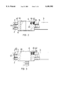
- FIG. 2 is a sectional view showing the operation of the first embodiment of the present invention in one state
- FIG. 3 is a sectional view showing the operation of the first embodiment of the present invention in another state
- FIG. 4 is a perspective assembled view of a second embodiment of the present invention.
- FIG. 5 is a sectional view taken along line V--V of FIG. 4;
- FIG. 6 is a sectional view taken along line VI--VI of FIG. 4;
- FIG. 7 is a sectional view of a third embodiment of the present invention.
- FIG. 8 is a sectional view of a fourth embodiment of the present invention.
- FIG. 9 is a perspective assembled view of a conventional ratchet wrench.
- FIG. 10 is a sectional view of the conventional ratchet wrench.
- the ratchet wrench of the present invention includes two clamping panels 2, a base seat 3, a rotary member 4, an engaging member 5, a pressing member 6 and a resilient member 61.
- the two clamping panels 2 are respectively formed with two circular holes 21 opposite to each other.
- One end of the base seat 3 is formed with a notch 31 in which a stopper member 32 is disposed.
- the stopper member 32 is forced by a spring 33 to abut against the engaging member 5.
- the engaging member 5 has two engaging sections 51 and a hole 52.
- a pin member 22 is passed through the hole 52 to pivotally connect the two clamping panels 2 with each other.
- the engaging sections 51 serve to engage with the rotary member 4 and make the same clockwisely or counterclockwisely rotate.
- the rotary member 4 is a cylindrical body formed with a hexagonal hole. A middle portion of the outer periphery of rotary member 4 is formed with multiple teeth 41. Two end portions of the outer periphery are two fitting sections 42 for fitting into the holes 21 of the two clamping panels 2. One of the fitting sections 42 is formed with a through hole 43 having a relatively small diameter stopper section 45 on inner side of the rotary member 4.
- the pressing member 6 is disposed in the through hole 43. An inner end of the pressing member 6 has a relatively small diameter. In this embodiment, the pressing member 6 is a cap member having a relatively small diameter close end.
- the pressing member 6 is pushed by the resilient member 61, whereby the small diameter section of the pressing member 6 projects outside the inner side 44 of the rotary member 4.
- the stopper section 45 prevents the pressing member 6 from dropping out of the through hole 43 of the rotary member 4.
- the resilient member 61 is a compression spring.
- An outer end of the resilient member 61 is fitted with a cap member 62 identical to the pressing member 6 in structure.
- FIGS. 4 to 6 show a second embodiment of the pressing member 6 of the present invention.
- Each end of the clamping panels 2 is formed with a circular hole 21 in which a rotary member 4 is rotatably disposed.
- the pressing member 6 is a steel ball 63 pushed by a C-shaped resilient member 61c made of a metal wire.
- the C-shaped resilient member 61c is positioned in an annular groove 46 of the fitting section 42.
- the annular groove 46 intersects the through hole 43 of the fitting section 42, whereby the resilient member 61 is stopped by the inner wall face 23 of the hole 21 of the clamping panel 2 from dropping out.
- This embodiment is advantageous in that the assembling procedure can be easily performed and the possibility of failure is low.
- FIG. 7 shows a third embodiment of the pressing member 6 of the present invention, in which the pressing member 6 is a steel ball 63 pushed by a resilient member 61 which is a compression spring.
- This embodiment has simple components and is manufactured at low cost and can be easily assembled.
- FIG. 8 shows a fourth embodiment of the present invention, in which the pressing member 6 is also a steel ball 63A pushed by a resilient member 61 identical to that of FIG. 7. Another steel ball 63B is disposed at an outer end of the resilient member 61. By means of the steel ball 63B, the frictional force between the resilient member 61 and the inner wall face 23 of the hole 21 of the clamping panel 2 is reduced.
- the present invention has less components and is manufactured at low cost.
- the pressing member 6 is stopped by the clamping panel 2 of the ratchet wrench itself from dropping out, so that the pressing member 6 can be pressed against a nut or a socket to facilitate operation.
Abstract
A ratchet wrench including two clamping panels, a base seat, a rotary member, an engaging member, a pressing member and a resilient member. The two clamping panels are respectively formed with two circular holes opposite to each other. The rotary member is rotatably disposed in the circular holes. A middle portion of an outer periphery of rotary member is formed with multiple teeth. Two end portions of the outer periphery are two fitting sections for fitting into the holes of the two clamping panels. One of the fitting sections is formed with a through hole in which the pressing member and the resilient member are disposed. The inner wall face of the circular hole of the clamping panel serves to stop the pressing member and the resilient member from dropping out. Therefore, the pressing member can be pressed against a nut or a socket to facilitate operation. Also, the structure is simple, easy to be assembled and firmly engaged.
Description
The present invention relates to a ratchet wrench in which the pressing member and the resilient member are stopped by the clamping panel of the ratchet wrench itself from dropping out.
FIGS. 9 and 10 show a conventional ratchet wrench composed of a grip 9, two clamping panels 92, a rotary member 93, two engaging members 96 and a pressing member 98. A front end of the grip 9 is formed with a hole 91 in which the rotary member 93 is installed. One end of the engaging member 96 is pivotally connected with the grip 9, while the other end of the engaging member 96 is engaged with the rotary member 93. By means of the two engaging members 96, the rotary member 93 can be clockwisely or counterclockwisely rotated.
The rotary member 93 has a toothed section 94 formed with a through hole 95 in which the pressing member 98 is disposed. The pressing member 98 includes a cap member 981, a compression spring 982 and a plug member 983. The compression spring 982 is positioned between the cap member 981 and the plug member 983. One end of the cap member 981 projects from an inner side 931 of the rotary member 93.
According to the above arrangement, the plug member 983 is used to block the spring 982 and prevent the pressing member 98 from dropping out of the through hole 95. Moreover, the front end of the engaging member 96 must be formed with a cut 97 for avoiding the plug member 983 of the pressing member 98. Therefore, it is troublesome to manufacture the ratchet wrench and it is difficult to assemble the pressing member 98. As a result, the cost for the ratchet wrench can be hardly reduced.
It is therefore a primary object of the present invention to provide a ratchet wrench in which the pressing member and the resilient member are stopped by the clamping panel of the ratchet wrench itself from dropping out. Therefore, the pressing member can be pressed against a nut or a socket to facilitate operation. The ratchet wrench has less components and can be easily manufactured and reliably assembled.
The present invention can be best understood through the following description and accompanying drawings, wherein:
FIG. 1 is a perspective exploded view of a first embodiment of the present invention;
FIG. 2 is a sectional view showing the operation of the first embodiment of the present invention in one state;
FIG. 3 is a sectional view showing the operation of the first embodiment of the present invention in another state;
FIG. 4 is a perspective assembled view of a second embodiment of the present invention;
FIG. 5 is a sectional view taken along line V--V of FIG. 4;
FIG. 6 is a sectional view taken along line VI--VI of FIG. 4;
FIG. 7 is a sectional view of a third embodiment of the present invention;
FIG. 8 is a sectional view of a fourth embodiment of the present invention;
FIG. 9 is a perspective assembled view of a conventional ratchet wrench; and
FIG. 10 is a sectional view of the conventional ratchet wrench.
Please refer to FIGS. 1 to 3. According to a first embodiment, the ratchet wrench of the present invention includes two clamping panels 2, a base seat 3, a rotary member 4, an engaging member 5, a pressing member 6 and a resilient member 61. The two clamping panels 2 are respectively formed with two circular holes 21 opposite to each other. One end of the base seat 3 is formed with a notch 31 in which a stopper member 32 is disposed. The stopper member 32 is forced by a spring 33 to abut against the engaging member 5. The engaging member 5 has two engaging sections 51 and a hole 52. A pin member 22 is passed through the hole 52 to pivotally connect the two clamping panels 2 with each other. The engaging sections 51 serve to engage with the rotary member 4 and make the same clockwisely or counterclockwisely rotate. The rotary member 4 is a cylindrical body formed with a hexagonal hole. A middle portion of the outer periphery of rotary member 4 is formed with multiple teeth 41. Two end portions of the outer periphery are two fitting sections 42 for fitting into the holes 21 of the two clamping panels 2. One of the fitting sections 42 is formed with a through hole 43 having a relatively small diameter stopper section 45 on inner side of the rotary member 4. The pressing member 6 is disposed in the through hole 43. An inner end of the pressing member 6 has a relatively small diameter. In this embodiment, the pressing member 6 is a cap member having a relatively small diameter close end. The pressing member 6 is pushed by the resilient member 61, whereby the small diameter section of the pressing member 6 projects outside the inner side 44 of the rotary member 4. The stopper section 45 prevents the pressing member 6 from dropping out of the through hole 43 of the rotary member 4. In this embodiment, the resilient member 61 is a compression spring. An outer end of the resilient member 61 is fitted with a cap member 62 identical to the pressing member 6 in structure. After the rotary member 4 is assembled with the clamping panels 2, the through hole 43 of the fitting section 42 is blocked by the inner wall face 23 of the hole 21 of the clamping panel 2. Therefore, the outer cap member 62 is stopped by the inner wall face 23 of the hole 21 of the clamping panel 2 to prevent the pressing member 6 from dropping outside.
FIGS. 4 to 6 show a second embodiment of the pressing member 6 of the present invention. Each end of the clamping panels 2 is formed with a circular hole 21 in which a rotary member 4 is rotatably disposed. In this embodiment, the pressing member 6 is a steel ball 63 pushed by a C-shaped resilient member 61c made of a metal wire. The C-shaped resilient member 61c is positioned in an annular groove 46 of the fitting section 42. The annular groove 46 intersects the through hole 43 of the fitting section 42, whereby the resilient member 61 is stopped by the inner wall face 23 of the hole 21 of the clamping panel 2 from dropping out. This embodiment is advantageous in that the assembling procedure can be easily performed and the possibility of failure is low.
FIG. 7 shows a third embodiment of the pressing member 6 of the present invention, in which the pressing member 6 is a steel ball 63 pushed by a resilient member 61 which is a compression spring. This embodiment has simple components and is manufactured at low cost and can be easily assembled.
FIG. 8 shows a fourth embodiment of the present invention, in which the pressing member 6 is also a steel ball 63A pushed by a resilient member 61 identical to that of FIG. 7. Another steel ball 63B is disposed at an outer end of the resilient member 61. By means of the steel ball 63B, the frictional force between the resilient member 61 and the inner wall face 23 of the hole 21 of the clamping panel 2 is reduced.
According to the above arrangement, the present invention has less components and is manufactured at low cost. The pressing member 6 is stopped by the clamping panel 2 of the ratchet wrench itself from dropping out, so that the pressing member 6 can be pressed against a nut or a socket to facilitate operation.
It is to be understood that the above description and drawings are only used for illustrating some embodiments of the present invention, not intended to limit the scope thereof. Any variation and derivation from the above description and drawings should be included in the scope of the present invention.
Claims (4)
1. A ratchet wrench comprising:
two clamping panels, a base seat disposed between the two clamping panels, a rotary member, an engaging member, a pressing member and a resilient member, the two clamping panels being respectively formed with two circular holes in aligned relationship with each other, one end of the base seat being formed with a notch in which a stopper member is disposed, the stopper member being biased to abut against the engaging member, the engaging member having two engaging sections and a hole, a pin member being passed through the hole and corresponding openings in the two clamping panels to pivotally connect the engaging member to the two clamping panels, the engaging sections serving to engage with the rotary member to prevent clockwise or counterclockwise rotation thereof, the rotary member being a cylindrical body formed with a hexagonal hole, the rotary member having an outer periphery with two end portions defining fitting sections for respectively fitting into the circular holes of the two clamping panels and a middle portion therebetween, the middle portion being formed with multiple teeth, one of the fitting sections being formed with a through hole having a relatively small diameter stopper section at a first end of the through hole adjacent an inner side of the rotary member, the pressing member being disposed in the through hole and being biased by a resilient member, whereby a relatively small diameter section of the pressing member projects outwardly from the inner side of the rotary member through hole, the stopper section preventing the pressing member from dropping out of the through hole of the rotary member, the through hole of the fitting section having a second end blocked by a respective inner wall face of the circular hole of a corresponding clamping panel for retaining the resilient member and the pressing member within the through hole.
2. The ratchet wrench as claimed in claim 1, wherein the pressing member is a first cap member having a relatively small diameter closed end and the resilient member is a compression spring, an outer end of the compression spring being fitted with a second cap member having an identical structure and shape as the first cap member.
3. The ratchet wrench as claimed in claim 1, wherein the pressing member is a steel ball biased by a C-shaped resilient member made of a metal wire, the C-shaped resilient member being positioned in an annular groove formed in the fitting section, the annular groove intersecting the through hole of the fitting section.
4. The ratchet wrench as claimed in claim 1, wherein the pressing member is a first steel ball biased by a first end of the resilient member, a second steel ball being disposed at a second end of the resilient member, the second steel ball contacting the inner wall face of the circular hole.
Priority Applications (2)
| Application Number | Priority Date | Filing Date | Title |
|---|---|---|---|
| US09/235,388 US6101902A (en) | 1999-01-22 | 1999-01-22 | Ratchet wrench |
| DE29901281U DE29901281U1 (en) | 1999-01-22 | 1999-01-26 | ratchet |
Applications Claiming Priority (2)
| Application Number | Priority Date | Filing Date | Title |
|---|---|---|---|
| US09/235,388 US6101902A (en) | 1999-01-22 | 1999-01-22 | Ratchet wrench |
| DE29901281U DE29901281U1 (en) | 1999-01-22 | 1999-01-26 | ratchet |
Publications (1)
| Publication Number | Publication Date |
|---|---|
| US6101902A true US6101902A (en) | 2000-08-15 |
Family
ID=26062203
Family Applications (1)
| Application Number | Title | Priority Date | Filing Date |
|---|---|---|---|
| US09/235,388 Expired - Fee Related US6101902A (en) | 1999-01-22 | 1999-01-22 | Ratchet wrench |
Country Status (2)
| Country | Link |
|---|---|
| US (1) | US6101902A (en) |
| DE (1) | DE29901281U1 (en) |
Cited By (24)
| Publication number | Priority date | Publication date | Assignee | Title |
|---|---|---|---|---|
| US6510765B2 (en) * | 2001-06-15 | 2003-01-28 | Chen Mu-Lin | Structure of a ratchet wheel having a ratchet wheel allowing a smooth teeth returning after application of the ratchet wrench |
| US20030131692A1 (en) * | 2002-01-11 | 2003-07-17 | Hsiu-Ching Huang | Socket wrench |
| US6612205B1 (en) * | 2002-03-19 | 2003-09-02 | Darwin Jones | Ratchet |
| US20040035257A1 (en) * | 2002-08-20 | 2004-02-26 | Hsien-Chung Tuan-Mu | Reversible ratcheting tool |
| US20040089110A1 (en) * | 2002-11-07 | 2004-05-13 | Chih-Ching Hsien | Metal piece attraction device on ratchet tool |
| US20040118252A1 (en) * | 2002-12-19 | 2004-06-24 | Norman Wexler | Power driven wrench |
| US20040149087A1 (en) * | 2003-02-04 | 2004-08-05 | Chin-Ching Hsien | Ratchet tool with magnetic engaging member |
| US20050160886A1 (en) * | 2002-03-22 | 2005-07-28 | Eggert Daniel M. | Low clearance socket and drive system |
| US20060070497A1 (en) * | 2003-03-07 | 2006-04-06 | Chuck Chang | Wrench having a locking device with a smaller driving angle |
| US20060096421A1 (en) * | 2004-11-08 | 2006-05-11 | Norman Wexler | Power driven wrench |
| US20080178717A1 (en) * | 2007-01-31 | 2008-07-31 | Zu-Shung Shu | Fast switch hand tool |
| CN101386163B (en) * | 2007-09-10 | 2010-08-25 | 徐日雄 | Tool with switch operation and convenient for carrying |
| US20110179912A1 (en) * | 2010-01-22 | 2011-07-28 | Chia-Ho Lin | Hand tool |
| US20120024115A1 (en) * | 2009-11-12 | 2012-02-02 | Meridian International Co., Ltd. | Rotary ratchet wrench |
| US9089953B2 (en) | 2013-08-26 | 2015-07-28 | Eduard Wille Gmbh & Co. Kg | Ratcheting tool with fine toothing |
| US9114509B2 (en) | 2012-02-14 | 2015-08-25 | Meridian International Co., Ltd. | Rotary ratcheting wrench |
| CN105555482A (en) * | 2013-09-19 | 2016-05-04 | 沃拉.沃克.赫尔曼.沃纳两合公司 | Socket spanner |
| US20160140432A1 (en) * | 2013-06-13 | 2016-05-19 | Stanley Works (Europe) Gmbh | Hand Tool Having an Electronic Identification Device |
| CN105772556A (en) * | 2014-12-22 | 2016-07-20 | 崧杰工业股份有限公司 | Forming method of ratchet wrench body part |
| US20160297054A1 (en) * | 2015-04-08 | 2016-10-13 | Hani A. Abunameh | Open end ratchet wrench |
| US20170182637A1 (en) * | 2015-12-27 | 2017-06-29 | Jei Mou Industrial Co., Ltd. | Lightweight Ratchet Wrench for withstanding Higher Torque Requirements |
| USD799948S1 (en) * | 2016-02-02 | 2017-10-17 | Deka Products Limited Partnership | Grasper claw |
| US10699597B2 (en) | 2016-02-02 | 2020-06-30 | Deka Products Limited Partnership | Modular electro-mechanical agent |
| USD1022639S1 (en) * | 2021-05-27 | 2024-04-16 | Hong Ann Tool Industries Co., Ltd. | Ratchet gear |
Families Citing this family (1)
| Publication number | Priority date | Publication date | Assignee | Title |
|---|---|---|---|---|
| US20040089108A1 (en) * | 2002-11-11 | 2004-05-13 | Chuck Chang | Wrench having a locking device with a smaller driving angle |
Citations (7)
| Publication number | Priority date | Publication date | Assignee | Title |
|---|---|---|---|---|
| US4722252A (en) * | 1987-03-02 | 1988-02-02 | Fulcher William A | Power driven wrench |
| US4791836A (en) * | 1987-04-01 | 1988-12-20 | Chicago Pneumatic Tool Company | Ratchet mechanism |
| US4819521A (en) * | 1982-05-06 | 1989-04-11 | A & E Manufacturing Company | Ratchet box wrench with offset handle |
| US5119701A (en) * | 1991-01-15 | 1992-06-09 | Wei Hung Yin | Base seat of a dual-directional ratchet wrench |
| US5687623A (en) * | 1996-07-23 | 1997-11-18 | Hsieh; Chih-Ching | Reversible socket wrench |
| US5848561A (en) * | 1996-11-06 | 1998-12-15 | Hsieh; Chih-Ching | Ratchet socket wrench and socket arrangement |
| US5857390A (en) * | 1996-12-24 | 1999-01-12 | Whiteford; Carlton L. | Reversible ratchet wrench including thin-walled sockets |
-
1999
- 1999-01-22 US US09/235,388 patent/US6101902A/en not_active Expired - Fee Related
- 1999-01-26 DE DE29901281U patent/DE29901281U1/en not_active Expired - Lifetime
Patent Citations (7)
| Publication number | Priority date | Publication date | Assignee | Title |
|---|---|---|---|---|
| US4819521A (en) * | 1982-05-06 | 1989-04-11 | A & E Manufacturing Company | Ratchet box wrench with offset handle |
| US4722252A (en) * | 1987-03-02 | 1988-02-02 | Fulcher William A | Power driven wrench |
| US4791836A (en) * | 1987-04-01 | 1988-12-20 | Chicago Pneumatic Tool Company | Ratchet mechanism |
| US5119701A (en) * | 1991-01-15 | 1992-06-09 | Wei Hung Yin | Base seat of a dual-directional ratchet wrench |
| US5687623A (en) * | 1996-07-23 | 1997-11-18 | Hsieh; Chih-Ching | Reversible socket wrench |
| US5848561A (en) * | 1996-11-06 | 1998-12-15 | Hsieh; Chih-Ching | Ratchet socket wrench and socket arrangement |
| US5857390A (en) * | 1996-12-24 | 1999-01-12 | Whiteford; Carlton L. | Reversible ratchet wrench including thin-walled sockets |
Cited By (38)
| Publication number | Priority date | Publication date | Assignee | Title |
|---|---|---|---|---|
| US6510765B2 (en) * | 2001-06-15 | 2003-01-28 | Chen Mu-Lin | Structure of a ratchet wheel having a ratchet wheel allowing a smooth teeth returning after application of the ratchet wrench |
| US20030131692A1 (en) * | 2002-01-11 | 2003-07-17 | Hsiu-Ching Huang | Socket wrench |
| US6612205B1 (en) * | 2002-03-19 | 2003-09-02 | Darwin Jones | Ratchet |
| US7975576B2 (en) * | 2002-03-22 | 2011-07-12 | Snap-On Incorporated | Low clearance socket and drive system |
| US20050160886A1 (en) * | 2002-03-22 | 2005-07-28 | Eggert Daniel M. | Low clearance socket and drive system |
| US7231851B2 (en) | 2002-08-20 | 2007-06-19 | Easco Hand Tools, Inc. | Reversible ratcheting tool |
| US20040035257A1 (en) * | 2002-08-20 | 2004-02-26 | Hsien-Chung Tuan-Mu | Reversible ratcheting tool |
| US6868759B2 (en) | 2002-08-20 | 2005-03-22 | Easco Hand Tools Inc. | Reversible ratcheting tool |
| US20050145076A1 (en) * | 2002-08-20 | 2005-07-07 | Easco Hand Tools, Inc. | Reversible ratcheting tool |
| US20040089110A1 (en) * | 2002-11-07 | 2004-05-13 | Chih-Ching Hsien | Metal piece attraction device on ratchet tool |
| US6761092B2 (en) * | 2002-11-07 | 2004-07-13 | Chih-Ching Hsien | Metal piece attraction device on ratchet tool |
| US20040118252A1 (en) * | 2002-12-19 | 2004-06-24 | Norman Wexler | Power driven wrench |
| US6845691B2 (en) * | 2003-02-04 | 2005-01-25 | Chih-Ching Hsien | Ratchet tool with magnetic engaging member |
| US20040149087A1 (en) * | 2003-02-04 | 2004-08-05 | Chin-Ching Hsien | Ratchet tool with magnetic engaging member |
| US7146881B2 (en) | 2003-03-07 | 2006-12-12 | Lotuskate Sports Industrial Co., Ltd. | Wrench having a locking device with a smaller driving angle |
| US20060070497A1 (en) * | 2003-03-07 | 2006-04-06 | Chuck Chang | Wrench having a locking device with a smaller driving angle |
| US20060096421A1 (en) * | 2004-11-08 | 2006-05-11 | Norman Wexler | Power driven wrench |
| US7089827B2 (en) | 2004-11-08 | 2006-08-15 | Norman Wexler | Power driven wrench |
| US7424837B2 (en) * | 2007-01-31 | 2008-09-16 | Zu-Shung Shu | Quick switch hand tool |
| US20080178717A1 (en) * | 2007-01-31 | 2008-07-31 | Zu-Shung Shu | Fast switch hand tool |
| CN101386163B (en) * | 2007-09-10 | 2010-08-25 | 徐日雄 | Tool with switch operation and convenient for carrying |
| US20120024115A1 (en) * | 2009-11-12 | 2012-02-02 | Meridian International Co., Ltd. | Rotary ratchet wrench |
| US8794110B2 (en) * | 2009-11-12 | 2014-08-05 | Meridian International Co., Ltd. | Rotary ratchet wrench |
| US20110179912A1 (en) * | 2010-01-22 | 2011-07-28 | Chia-Ho Lin | Hand tool |
| US9114509B2 (en) | 2012-02-14 | 2015-08-25 | Meridian International Co., Ltd. | Rotary ratcheting wrench |
| US20160140432A1 (en) * | 2013-06-13 | 2016-05-19 | Stanley Works (Europe) Gmbh | Hand Tool Having an Electronic Identification Device |
| US9089953B2 (en) | 2013-08-26 | 2015-07-28 | Eduard Wille Gmbh & Co. Kg | Ratcheting tool with fine toothing |
| CN105555482A (en) * | 2013-09-19 | 2016-05-04 | 沃拉.沃克.赫尔曼.沃纳两合公司 | Socket spanner |
| US20160193724A1 (en) * | 2013-09-19 | 2016-07-07 | Wera Werk Hermann Werner Gmbh & Co. Kg | Socket Spanner |
| CN105772556A (en) * | 2014-12-22 | 2016-07-20 | 崧杰工业股份有限公司 | Forming method of ratchet wrench body part |
| US20160297054A1 (en) * | 2015-04-08 | 2016-10-13 | Hani A. Abunameh | Open end ratchet wrench |
| US11192220B2 (en) * | 2015-04-08 | 2021-12-07 | Hani A. Abunameh | Open end ratchet wrench |
| US20170182637A1 (en) * | 2015-12-27 | 2017-06-29 | Jei Mou Industrial Co., Ltd. | Lightweight Ratchet Wrench for withstanding Higher Torque Requirements |
| US9975223B2 (en) * | 2015-12-27 | 2018-05-22 | Jei Mou Industrial Co., Ltd. | Lightweight ratchet wrench for withstanding higher torque requirements |
| USD799948S1 (en) * | 2016-02-02 | 2017-10-17 | Deka Products Limited Partnership | Grasper claw |
| US10699597B2 (en) | 2016-02-02 | 2020-06-30 | Deka Products Limited Partnership | Modular electro-mechanical agent |
| US11521517B2 (en) | 2016-02-02 | 2022-12-06 | Deka Products Limited Partnership | Modular electro-mechanical agent |
| USD1022639S1 (en) * | 2021-05-27 | 2024-04-16 | Hong Ann Tool Industries Co., Ltd. | Ratchet gear |
Also Published As
| Publication number | Publication date |
|---|---|
| DE29901281U1 (en) | 1999-05-12 |
Similar Documents
| Publication | Publication Date | Title |
|---|---|---|
| US6101902A (en) | Ratchet wrench | |
| US4501045A (en) | Self-locking hinge | |
| CN102019595B (en) | Ratchet wrench handle | |
| US5685204A (en) | Miniature reversible ratcheting screwdriver | |
| TWI758971B (en) | Reversible ratchet device | |
| US20070256525A1 (en) | Rotary wrench structure | |
| US6176158B1 (en) | Pincers | |
| US9669525B2 (en) | Palm wrench | |
| US4528873A (en) | Twist set ratchet wrench | |
| US6308382B1 (en) | Locking assembly for a metal watchband | |
| US6446530B1 (en) | Ratchet wrench | |
| JP3109631U (en) | Rotating connection collet for pneumatic electric impact rotary tool | |
| US6609444B1 (en) | Switching lever for ratchet tools | |
| US20170106504A1 (en) | Wrench for operating objects of different sizes | |
| US10384334B2 (en) | Ratchet screwdriver | |
| US5197358A (en) | Socket wrench | |
| US20130319184A1 (en) | Reversing device for a ratchet wrench | |
| US5211087A (en) | Multiple drive ratchet wrench | |
| US20020194964A1 (en) | Ratchet structure of screwdriver | |
| US5618128A (en) | Wiper arm connector | |
| US20180345462A1 (en) | Tool attachment | |
| US20170197298A1 (en) | Stepless wrench with toothless drive | |
| US6945142B1 (en) | Socket | |
| US5894766A (en) | Ratchet screwdriver | |
| US20060053962A1 (en) | Retainer of spindle tube device |
Legal Events
| Date | Code | Title | Description |
|---|---|---|---|
| FPAY | Fee payment |
Year of fee payment: 4 |
|
| REMI | Maintenance fee reminder mailed | ||
| LAPS | Lapse for failure to pay maintenance fees | ||
| LAPS | Lapse for failure to pay maintenance fees |
Free format text: PATENT EXPIRED FOR FAILURE TO PAY MAINTENANCE FEES (ORIGINAL EVENT CODE: EXP.); ENTITY STATUS OF PATENT OWNER: SMALL ENTITY |
|
| STCH | Information on status: patent discontinuation |
Free format text: PATENT EXPIRED DUE TO NONPAYMENT OF MAINTENANCE FEES UNDER 37 CFR 1.362 |
|
| FP | Lapsed due to failure to pay maintenance fee |
Effective date: 20080815 |