US6120175A - Apparatus and method for controlled chemical blending - Google Patents
Apparatus and method for controlled chemical blending Download PDFInfo
- Publication number
- US6120175A US6120175A US09/352,981 US35298199A US6120175A US 6120175 A US6120175 A US 6120175A US 35298199 A US35298199 A US 35298199A US 6120175 A US6120175 A US 6120175A
- Authority
- US
- United States
- Prior art keywords
- chemical
- blending
- chemicals
- automatic inlet
- vessels
- Prior art date
- Legal status (The legal status is an assumption and is not a legal conclusion. Google has not performed a legal analysis and makes no representation as to the accuracy of the status listed.)
- Expired - Fee Related
Links
Images

Classifications
-
- B—PERFORMING OPERATIONS; TRANSPORTING
- B01—PHYSICAL OR CHEMICAL PROCESSES OR APPARATUS IN GENERAL
- B01F—MIXING, e.g. DISSOLVING, EMULSIFYING OR DISPERSING
- B01F35/00—Accessories for mixers; Auxiliary operations or auxiliary devices; Parts or details of general application
- B01F35/80—Forming a predetermined ratio of the substances to be mixed
- B01F35/88—Forming a predetermined ratio of the substances to be mixed by feeding the materials batchwise
- B01F35/881—Forming a predetermined ratio of the substances to be mixed by feeding the materials batchwise by weighing, e.g. with automatic discharge
-
- B—PERFORMING OPERATIONS; TRANSPORTING
- B01—PHYSICAL OR CHEMICAL PROCESSES OR APPARATUS IN GENERAL
- B01F—MIXING, e.g. DISSOLVING, EMULSIFYING OR DISPERSING
- B01F33/00—Other mixers; Mixing plants; Combinations of mixers
- B01F33/80—Mixing plants; Combinations of mixers
Definitions
- This invention pertains to an apparatus and method for controlled chemical blending in general.
- the invention provides for the high speed chemical blending of a variety of chemicals through a pair of automatic inlet valves, one with a large inlet orifice and one with a relatively much smaller inlet orifice.
- the processes used in semiconductor manufacturing require the blending of two or more chemicals in the ordinary case.
- the correct percentage of each chemical in the blend is critical and typically must be within a tolerance of 0.5% by weight. Not only is the correct percentage of the blend critical, but rapidly obtaining and maintaining the mixture is important as well.
- a third problem faced is the need to change the mixture at any time.
- the prior art discloses a variety of devices designed for mixing.
- the Falcoff, et al patent, U.S. Pat. No. 4,403,866 discloses a process for making paints which meet the requirements of a standard paint formula loaded in a computer. A colorimeter is used to determine whether the paint is within the tolerance values of the standard paint.
- the Borrow patent U.S. Pat. No. 4,509,863 discloses an apparatus for mixing milk with flavoring and fluoride.
- the device consists of two sets of three vessels.
- the three vessels are constructed so that their internal volumes are in the same ratio as the volumes of liquid in the final beverage.
- the Beerier patent U.S. Pat. No. 4,671,892 discloses a device for making soap on site by first weighing the materials to be mixed, then mixing them and transferring the mixture for storage at the end of a predetermined reaction time.
- the Patel, et al patent, U.S. Pat. No. 5,340,210 discloses a device for blending chemicals which includes a single blending vat and a pump that includes forward and reverse directions and has a high and low speed function.
- the Patel vat is initially filled at high speed and, prior to the introduction of the full amount of chemical to be blended, is shifted to the low speed for the precise addition of chemical.
- This system is mirrored by the Major patent, U.S. Pat. No. 5,558,435 and the O'Dougherty, et al patent, U.S. Pat. No. 5,522,660.
- a primary drawback of the chemical blending systems known in the art is the inability to create accurate chemical blends within a very narrow range of tolerance at high speed. Other drawbacks are the inability to obtain the desired chemical balance quickly and accurately and maintain a constant flow of the blend as required. Further, the prior art points out the need for a chemical blending system that also has the ability to rapidly and actively change chemical blends when desired. It, therefore, is an objective of the chemical blending system of the present invention to provide for a continuously high speed apparatus and method of creating chemical blends within a very small range of tolerance by weight that is capable of manipulation of the chemical blend so as to obtain and maintain the proper mixture over time and which can change the blend as desired.
- the chemical blending system of the present invention includes more than one chemical blending vessel with tops and bottoms and with inlets at the tops.
- a pair of automatic inlet valves is connected to each chemical blending vessel, one with a large inlet orifice and one with a relatively much smaller inlet orifice.
- At least two chemical batch tanks for holding chemicals to be blended are connected to the pair of automatic inlet valves.
- a pump is connected to the chemical batch tanks for high speed delivery of chemicals from the chemical batch tank to the automatic inlet valves.
- a controller for controlling the transfer of chemicals and opening and closing the automatic inlet valves is connected to the system and to a weight cell which is utilized for measuring the weight of chemicals added to the chemical blending vessels.
- a discharge line is connected to the bottom of each of the chemical blending vessels and to a receiving station.
- the discharge line contains a static mixer and is connected to a discharge line pump, a filter, and a sampling means so that a resultant blend of chemicals is mixed, filtered and sampled after discharge from the chemical blending system and prior to delivery to the receiving station.
- Further embodiments of the invention include chemical blending vessels with cone shaped bottoms so as to mechanically induce blending of the chemicals as they are added at high speed from the tops and so as to assist in the complete evaluation of chemicals when desired.
- a separate pair of automatic inlet valves is provided for use by each individual chemical blending tank that is connected to the system.
- a back-up discharge line pump is provided that is interconnected between the chemical blending vessels so that auxiliary discharge line pump action is available.
- a drain is connected to the bottom of the chemical blending vessels and to a blended chemical recovery tank for the high speed drain of said chemical blending vessels when necessary.
- a corresponding chemical blending method is provided as disclosed and claimed more fully hereafter which includes the step of filling the chemical blending vessel at high speed until a majority of the desired chemical has been received as determined by a weight cell, at which point a controller switches the automatic inlet valve with a relatively much smaller inlet orifice for the final high speed delivery of the minority of the desired chemical as determined by weight.
- the step includes the step of high speed addition of 97% of the desired chemical by weight through the first automatic inlet valve with a large inlet orifice and the addition of the remaining 3% of the desired chemical through the automatic inlet valve with a relatively much smaller inlet orifice.
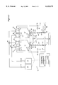
- FIG. 1 is a schematic diagram of a preferred embodiment of the chemical blending system of the present invention.
- FIG. 2 is a schematic diagram illustrating another preferred embodiment of the invention disclosed in FIG. 1.
- a chemical blending system 10 includes chemical blending vessels 12 with tops 14 and bottoms 16. Tops 14 have inlets 18. Connected to inlets 18 are automatic inlet valves 20. Automatic inlet valves 20 comprise a pair of inlet valves, one automatic inlet valve 22 with a large inlet orifice and one automatic inlet valve 24 with a relatively much smaller inlet orifice. Chemical batch tanks 26 are connected through pumps 28 to automatic inlet valves 20. Chemical blending vessels 12 are connected to and rest upon weight cell devices 30. Controller (computer) 32 is connected to weight cell devices 30 and to chemical blending system 10 for the remote control and operation of chemical blending system 10, including all pumps, valves and associated electronic and mechanical equipment.
- Discharge line 34 is connected to the bottom 16 of chemical blending vessel 12 and, ultimately, to the remote receiving station (not shown).
- Discharge line 34 includes discharge line pumps 36, pulsation dampeners 38, filters 40, and static mixer 42. Additionally, discharge line 34 includes recirculation line 44 connected to the top 14 of chemical blending vessel 12. Recirculation line 44 includes sampling device 46.
- discharge line 34 further includes a third alternate discharge line pump 48 as back-up. Further, discharge line 34 includes drain valves 50 and drain lines 52 connected to remote blended chemical recovery tank 54. Prior to delivery to the remote receiving station, discharge line 34 further includes receiving station filters 56. As shown in FIGS. 1 and 2, the bottom 16 of chemical blending vessels 12, preferably, is conical in shape.
- FIG. 2 another preferred embodiment of the present invention is illustrated wherein chemical batch tanks 26 are connected through pumps 28 to individual pairs of automatic inlet valves 20.
- automatic inlet valves 20 can be constructed to accommodate a particular chemical, thereby reducing the corrosive effect over time of switching chemicals from batch to batch through a single pair of automatic inlet valves 20.
- the chemical blending system 10 of the present invention introduces chemicals from chemical batch tanks 26 into chemical blending vessels 12, one at a time, through automatic valves 58 controlled by controller/computer 32.
- Controller/computer 32 directs the selected chemical from one of the chemical batch tanks 26 to automatic inlet valve 20.
- Automatic inlet valve 20 again, consists of a pair of inlet valves, valve 22 with a large inlet orifice and valve 24 with a relatively much smaller inlet orifice.
- Valve 22 is utilized for introducing the bulk flow of the chemical at high speed to chemical blending vessel 12.
- Valve 24, again sized with a smaller orifice allows precise control, but still at high speed, of the chemical to be delivered, and is utilized to complete the flow.
- Controller 32 constantly measures the weight of chemical adding through feedback from weight cell device 30. After the majority of the chemical by weight has been added through valve 22, controller 32 automatically closes valve 22 and opens valve 24 for the high speed introduction of the remainder of chemical required up to the required weight as measured by weight cell device 30.
- valve 22 is utilized so as to allow chemical flow until approximately 97% of the required weight is added to chemical blending vessel 12. Thereafter, valve 24 is opened to fill the remaining 3% of the required weight. Obviously, these percentages can be adjusted through the controller 32 as required. Valves 22 and 24 can be opened and closed manually, as is known in the art. The required weights of each chemical for whatever chemical blend is desired is determined beforehand and controlled through programmable logic controller/computer 32. Further, controller 32 can be any computer now known or hereafter developed.
- the chemical blending vessel 12 has received all of the required chemicals at the required weight percentages, further mixture is accomplished by circulating the mixture from chemical blending vessel 12 through discharge line 34, by means of discharge line pump 36, through pulsation damper 38, filters 40 and static mixer 42.
- the blended chemical Prior to delivery to the remote receiving station, the blended chemical is directed by controller 32 through recirculation line 44 and, at that point, sampling device 46 is utilized to sample the chemical so as to determine whether the correct chemical blend has been achieved. Any known chemical analyzer can be used for sampling. Correction of the chemical blend can then be accomplished so as to prevent the delivery of an inaccurate or unacceptable blend to the remote receiving station.
- controller 32 opens automatic valve 58 in discharge line 34 so as to direct the chemical blend through receiving station filters 56 for ultimate delivery to the receiving station.
- each chemical blending vessel 12 has its own dedicated pump 36, as well as a third/alternate discharge line pump 48 which is used as a common spare.
- the chemical weight required for the mixture is programmed and set through the controller 32. Once set, HF is allowed to flow, by means of pump 28 through a connection line and, by means of automatic valve 58 into blending vessel 12 through automatic inlet valve 20. To begin with, the HF flows through valve 22 with a large inlet orifice. Once chemical blending vessel 12 receives 97%, or any other percentage as required for rapid filing, of the required weight of HF, valve 22 is automatically closed and fine control valve 24 is opened to allow the final 3% of HF to reach the required weight as determined by weight cell 30.
- HNO3 is flowed through automatic valve 58 to automatic inlet valves 20 and initially through valve 22 with a large inlet orifice.
- valve 22 is automatically closed and fine control valve 24 is opened to allow the final 3% of HNO3 to reach the required weight.
- the Acetic is flowed through valve 22 into chemical blending vessel 12.
- valve 22 is automatically closed and fine control valve is automatically opened to allow the final 3% of Acetic to reach the required weight.
- the weight cell 30, in conjunction with controller 32 through automatic operation of appropriate valves controls the required weight of each chemical.
- discharge line pump 36 starts and the mixture is pumped through pulsation damper 38, filters 40, static mixer 42 and back to chemical blending vessel 12 through recirculation line 44.
- sampling device 46 is utilized to determine whether the correct chemical blend has, in fact, been achieved.
- the chemical blend will continue to recirculate until adequate mixing, or formulation is acquired.
- the chemical blend is ready for distribution.
- automatic valve 58 in discharge line 34 directs the chemical blend through receiving station filters 36 and on to the receiving station for utilization.
- chemical blending vessel 12' begins filling in the same sequence as just described. Once chemical blending vessel 12' has reached the required chemical blend mixture, discharge line pump 36 connected with chemical blending vessel 12' starts and the mixture is pumped through pulsation damper 38, filters 40 and static mixer 42 associated with chemical blending vessel 12' back through recirculation line 44 to the top of chemical blending vessel 12'. It should be noted that in addition to this means for blending the chemical, the introduction of the chemical at the top, in conjunction with the conical shape of the bottom 16, of chemical blending vessels 12 and 12' also ensures thorough mixing of chemicals. Once the chemical blend has been sampled by means of sampling device 46 and found to meet the required specifications, the chemical blend goes to distribution as previously discussed through receiving station filters 56.
- drain valve 50 is automatically opened while associated outlet valves and pumps and discharge line 34 are closed, so as to allow any remaining chemical blend to drain from the chemical blending vessel 12 to remote chemical recovery tank 54.
- the conical shape of the bottom 16 enhances the ability of the chemical blending vessels 12 to drain rapidly and completely.
- chemical blending vessel 12' will be full and ready to deliver appropriately blended chemical. If distribution is not needed, chemical blending vessel 12' will continue to recirculate. When chemical blending vessel 12 is sufficiently drained, and cleaned as necessary and desired, the filling process begins again.
- chemical blending vessel 12' When chemical blending vessel 12' reaches a low point, the discharge line 34 is closed and the drain line 50 is automatically opened to allow it to drain. When chemical blending vessel 12' reaches a low point in the delivery of appropriately blended chemical, chemical blending vessel 12 will be full with appropriately mixed and blended chemicals so that chemical blending vessel 12' will be stopped and delivery from chemical blending vessel 12 will be initiated if needed. As result, an essentially uninterrupted, continuous flow of appropriately blended chemical is provided to the remote receiving station.
- any number of chemical batch tanks 26 can be utilized, as well as any number of chemical blending vessels 12, 12', and the like.
- the chemical blending system 10 of the present invention has been disclosed in connection with the accurate chemical mixing and blending of chemicals for use in the semiconductor industry, it should be appreciated that the blending system of the present invention can be used in other applications.
- the present invention provides an accurate, multiply efficient means for blending fluids rapidly and automatically and provides an essentially uninterrupted continuous flow of mixed product as desired.
- the blending system of the present invention has important advantages over the prior art for accuracy, efficiency, and continuity of delivery of blended materials.
Abstract
A chemical blending system having more than one chemical blending vessel (12, 12') with inlets at the top. A pair of automatic inlet valves are connected to the top of each chemical blending vessel, one with a large inlet orifice and one with a relatively much smaller inlet orifice. At least two chemical batch tanks are connected to the pair of automatic inlet valves and chemicals to be mixed are delivered there at high speed by pumps. Weight cell devices (30) are attached to the bottom of each blending vessel. A controller/computer is connected for the automatic control of pumps (28, 36) and valves (20, 50, 58). A discharge line is connected to the bottom of blending vessels and to a receiving station, and includes pulsation dampeners (38), filters (40) and static mixers (42). A sampling device (46) is connected a recirculation line for the sampling of the blended chemical during recirculation and prior to delivery. Drain valve and drain line are connected to the bottom of the blending vessel for the draining and delivery of unused chemical to remote recovery tank (54). When one blending vessel is delivering appropriately blended chemical, another chemical blending vessel is being filled so that an essentially continuous, uninterrupted supply of appropriately and quickly blended chemical is available.
Description
This invention pertains to an apparatus and method for controlled chemical blending in general. In particular, the invention provides for the high speed chemical blending of a variety of chemicals through a pair of automatic inlet valves, one with a large inlet orifice and one with a relatively much smaller inlet orifice. The processes used in semiconductor manufacturing require the blending of two or more chemicals in the ordinary case. The correct percentage of each chemical in the blend is critical and typically must be within a tolerance of 0.5% by weight. Not only is the correct percentage of the blend critical, but rapidly obtaining and maintaining the mixture is important as well. A third problem faced is the need to change the mixture at any time. The prior art discloses a variety of devices designed for mixing. The Falcoff, et al patent, U.S. Pat. No. 4,403,866 discloses a process for making paints which meet the requirements of a standard paint formula loaded in a computer. A colorimeter is used to determine whether the paint is within the tolerance values of the standard paint.
The Borrow patent, U.S. Pat. No. 4,509,863 discloses an apparatus for mixing milk with flavoring and fluoride. The device consists of two sets of three vessels. The three vessels are constructed so that their internal volumes are in the same ratio as the volumes of liquid in the final beverage.
The Beerier patent, U.S. Pat. No. 4,671,892 discloses a device for making soap on site by first weighing the materials to be mixed, then mixing them and transferring the mixture for storage at the end of a predetermined reaction time.
More directly related prior art patents are disclosed in Mackay, et al, U.S. Pat. No. 5,288,145, for a device that monitors the weight of a mixing tank as various switches are actuated to add the required ingredients. No precise requirements of mixing are disclosed and the control over dilution is accomplished by varying the speed of the pump adding the dilutant.
The Patel, et al patent, U.S. Pat. No. 5,340,210 discloses a device for blending chemicals which includes a single blending vat and a pump that includes forward and reverse directions and has a high and low speed function. The Patel vat is initially filled at high speed and, prior to the introduction of the full amount of chemical to be blended, is shifted to the low speed for the precise addition of chemical. This system is mirrored by the Major patent, U.S. Pat. No. 5,558,435 and the O'Dougherty, et al patent, U.S. Pat. No. 5,522,660.
Other means and methods exist for the creation of a proper chemical blend by dilution and otherwise such as disclosed in the Owczarz patent, U.S. Pat. No. 5,409,310, which utilizes aspirator injectors which have a suction port which draws from a mixing tank so that as a primary fluid flows through the aspirator injectors, the already diluted additive is further diluted.
A primary drawback of the chemical blending systems known in the art is the inability to create accurate chemical blends within a very narrow range of tolerance at high speed. Other drawbacks are the inability to obtain the desired chemical balance quickly and accurately and maintain a constant flow of the blend as required. Further, the prior art points out the need for a chemical blending system that also has the ability to rapidly and actively change chemical blends when desired. It, therefore, is an objective of the chemical blending system of the present invention to provide for a continuously high speed apparatus and method of creating chemical blends within a very small range of tolerance by weight that is capable of manipulation of the chemical blend so as to obtain and maintain the proper mixture over time and which can change the blend as desired.
Accordingly, the chemical blending system of the present invention includes more than one chemical blending vessel with tops and bottoms and with inlets at the tops. A pair of automatic inlet valves is connected to each chemical blending vessel, one with a large inlet orifice and one with a relatively much smaller inlet orifice. At least two chemical batch tanks for holding chemicals to be blended are connected to the pair of automatic inlet valves. A pump is connected to the chemical batch tanks for high speed delivery of chemicals from the chemical batch tank to the automatic inlet valves. A controller for controlling the transfer of chemicals and opening and closing the automatic inlet valves is connected to the system and to a weight cell which is utilized for measuring the weight of chemicals added to the chemical blending vessels. Further, a discharge line is connected to the bottom of each of the chemical blending vessels and to a receiving station. The discharge line contains a static mixer and is connected to a discharge line pump, a filter, and a sampling means so that a resultant blend of chemicals is mixed, filtered and sampled after discharge from the chemical blending system and prior to delivery to the receiving station.
Further embodiments of the invention include chemical blending vessels with cone shaped bottoms so as to mechanically induce blending of the chemicals as they are added at high speed from the tops and so as to assist in the complete evaluation of chemicals when desired. Further, in a preferred embodiment, a separate pair of automatic inlet valves is provided for use by each individual chemical blending tank that is connected to the system. In a further embodiment, a back-up discharge line pump is provided that is interconnected between the chemical blending vessels so that auxiliary discharge line pump action is available. Still, in a further embodiment, a drain is connected to the bottom of the chemical blending vessels and to a blended chemical recovery tank for the high speed drain of said chemical blending vessels when necessary.
A corresponding chemical blending method is provided as disclosed and claimed more fully hereafter which includes the step of filling the chemical blending vessel at high speed until a majority of the desired chemical has been received as determined by a weight cell, at which point a controller switches the automatic inlet valve with a relatively much smaller inlet orifice for the final high speed delivery of the minority of the desired chemical as determined by weight. In a further preferred embodiment of this method, the step includes the step of high speed addition of 97% of the desired chemical by weight through the first automatic inlet valve with a large inlet orifice and the addition of the remaining 3% of the desired chemical through the automatic inlet valve with a relatively much smaller inlet orifice.
Other objects, features and advantages of the present invention will become more fully apparent from the following detailed description of the preferred embodiment, the appended claims and the accompanying drawings in which:
FIG. 1 is a schematic diagram of a preferred embodiment of the chemical blending system of the present invention; and
FIG. 2 is a schematic diagram illustrating another preferred embodiment of the invention disclosed in FIG. 1.
The preferred embodiment of the present invention is illustrated by way of example in FIGS. 1-2. With specific reference to FIG. 1, a chemical blending system 10 includes chemical blending vessels 12 with tops 14 and bottoms 16. Tops 14 have inlets 18. Connected to inlets 18 are automatic inlet valves 20. Automatic inlet valves 20 comprise a pair of inlet valves, one automatic inlet valve 22 with a large inlet orifice and one automatic inlet valve 24 with a relatively much smaller inlet orifice. Chemical batch tanks 26 are connected through pumps 28 to automatic inlet valves 20. Chemical blending vessels 12 are connected to and rest upon weight cell devices 30. Controller (computer) 32 is connected to weight cell devices 30 and to chemical blending system 10 for the remote control and operation of chemical blending system 10, including all pumps, valves and associated electronic and mechanical equipment.
In a preferred embodiment, discharge line 34 further includes a third alternate discharge line pump 48 as back-up. Further, discharge line 34 includes drain valves 50 and drain lines 52 connected to remote blended chemical recovery tank 54. Prior to delivery to the remote receiving station, discharge line 34 further includes receiving station filters 56. As shown in FIGS. 1 and 2, the bottom 16 of chemical blending vessels 12, preferably, is conical in shape.
Referring now to FIG. 2, another preferred embodiment of the present invention is illustrated wherein chemical batch tanks 26 are connected through pumps 28 to individual pairs of automatic inlet valves 20. As a result, automatic inlet valves 20 can be constructed to accommodate a particular chemical, thereby reducing the corrosive effect over time of switching chemicals from batch to batch through a single pair of automatic inlet valves 20.
In general, the chemical blending system 10 of the present invention introduces chemicals from chemical batch tanks 26 into chemical blending vessels 12, one at a time, through automatic valves 58 controlled by controller/computer 32. Controller/computer 32 directs the selected chemical from one of the chemical batch tanks 26 to automatic inlet valve 20. Automatic inlet valve 20, again, consists of a pair of inlet valves, valve 22 with a large inlet orifice and valve 24 with a relatively much smaller inlet orifice. Valve 22 is utilized for introducing the bulk flow of the chemical at high speed to chemical blending vessel 12. Valve 24, again sized with a smaller orifice, allows precise control, but still at high speed, of the chemical to be delivered, and is utilized to complete the flow. The point is, pump 28 runs at the same speed for the entire process and the precise addition of chemicals is accomplished through selective use of valves 22 and 24. Controller 32 constantly measures the weight of chemical adding through feedback from weight cell device 30. After the majority of the chemical by weight has been added through valve 22, controller 32 automatically closes valve 22 and opens valve 24 for the high speed introduction of the remainder of chemical required up to the required weight as measured by weight cell device 30. In a preferred embodiment, valve 22 is utilized so as to allow chemical flow until approximately 97% of the required weight is added to chemical blending vessel 12. Thereafter, valve 24 is opened to fill the remaining 3% of the required weight. Obviously, these percentages can be adjusted through the controller 32 as required. Valves 22 and 24 can be opened and closed manually, as is known in the art. The required weights of each chemical for whatever chemical blend is desired is determined beforehand and controlled through programmable logic controller/computer 32. Further, controller 32 can be any computer now known or hereafter developed.
By means of the present invention then, high speed delivery of chemicals to be blended is enabled since the automatic inlet valve 22 with a large inlet orifice is automatically cut off when the appropriate initial, major, percentage of chemical by weight is achieved and the automatic inlet valve 24 with a relatively smaller orifice is opened and flow is controlled by the size of the orifice, not the speed of the pump. Again, this enables the delivery and mixing of chemicals, from the majority of the chemical to be mixed through the remaining minority, all of it at high speed.
Once the chemical blending vessel 12 has received all of the required chemicals at the required weight percentages, further mixture is accomplished by circulating the mixture from chemical blending vessel 12 through discharge line 34, by means of discharge line pump 36, through pulsation damper 38, filters 40 and static mixer 42. Prior to delivery to the remote receiving station, the blended chemical is directed by controller 32 through recirculation line 44 and, at that point, sampling device 46 is utilized to sample the chemical so as to determine whether the correct chemical blend has been achieved. Any known chemical analyzer can be used for sampling. Correction of the chemical blend can then be accomplished so as to prevent the delivery of an inaccurate or unacceptable blend to the remote receiving station. Once the desired chemical blend is achieved in one of the chemical blending vessels 12, controller 32 opens automatic valve 58 in discharge line 34 so as to direct the chemical blend through receiving station filters 56 for ultimate delivery to the receiving station. As illustrated, each chemical blending vessel 12 has its own dedicated pump 36, as well as a third/alternate discharge line pump 48 which is used as a common spare.
By way of further example, the use of the system for mixing an acid comprised of HF, HNO3 and Acetic will be discussed. To begin with, the chemical weight required for the mixture is programmed and set through the controller 32. Once set, HF is allowed to flow, by means of pump 28 through a connection line and, by means of automatic valve 58 into blending vessel 12 through automatic inlet valve 20. To begin with, the HF flows through valve 22 with a large inlet orifice. Once chemical blending vessel 12 receives 97%, or any other percentage as required for rapid filing, of the required weight of HF, valve 22 is automatically closed and fine control valve 24 is opened to allow the final 3% of HF to reach the required weight as determined by weight cell 30. After chemical blending vessel 12 receives the appropriate weight of HF, HNO3 is flowed through automatic valve 58 to automatic inlet valves 20 and initially through valve 22 with a large inlet orifice. Once chemical blending vessel 12 receives 97% of the required weight of HNO3, valve 22 is automatically closed and fine control valve 24 is opened to allow the final 3% of HNO3 to reach the required weight. After the chemical blending vessel 12 receives the required HNO3 by weight, the Acetic is flowed through valve 22 into chemical blending vessel 12. Once chemical blending vessel 12 receives 97% of the required weight of Acetic, valve 22 is automatically closed and fine control valve is automatically opened to allow the final 3% of Acetic to reach the required weight. As can be seen, the weight cell 30, in conjunction with controller 32 through automatic operation of appropriate valves, controls the required weight of each chemical.
Once the chemical blending vessel 12 reaches the required capacity and blend, discharge line pump 36 starts and the mixture is pumped through pulsation damper 38, filters 40, static mixer 42 and back to chemical blending vessel 12 through recirculation line 44. At this point, sampling device 46 is utilized to determine whether the correct chemical blend has, in fact, been achieved. The chemical blend will continue to recirculate until adequate mixing, or formulation is acquired. At this point, the chemical blend is ready for distribution. When distribution is required, automatic valve 58 in discharge line 34 directs the chemical blend through receiving station filters 36 and on to the receiving station for utilization.
When chemical blending vessel 12 has completed its "fill" operation as just described, chemical blending vessel 12' begins filling in the same sequence as just described. Once chemical blending vessel 12' has reached the required chemical blend mixture, discharge line pump 36 connected with chemical blending vessel 12' starts and the mixture is pumped through pulsation damper 38, filters 40 and static mixer 42 associated with chemical blending vessel 12' back through recirculation line 44 to the top of chemical blending vessel 12'. It should be noted that in addition to this means for blending the chemical, the introduction of the chemical at the top, in conjunction with the conical shape of the bottom 16, of chemical blending vessels 12 and 12' also ensures thorough mixing of chemicals. Once the chemical blend has been sampled by means of sampling device 46 and found to meet the required specifications, the chemical blend goes to distribution as previously discussed through receiving station filters 56.
By way of a further embodiment of the present invention, when chemical blending vessel 12 reaches a low point, as previously determined by the operator through controller 32, drain valve 50 is automatically opened while associated outlet valves and pumps and discharge line 34 are closed, so as to allow any remaining chemical blend to drain from the chemical blending vessel 12 to remote chemical recovery tank 54. Here, the conical shape of the bottom 16 enhances the ability of the chemical blending vessels 12 to drain rapidly and completely. Simultaneously, when chemical blending vessel 12 is draining, chemical blending vessel 12' will be full and ready to deliver appropriately blended chemical. If distribution is not needed, chemical blending vessel 12' will continue to recirculate. When chemical blending vessel 12 is sufficiently drained, and cleaned as necessary and desired, the filling process begins again.
When chemical blending vessel 12' reaches a low point, the discharge line 34 is closed and the drain line 50 is automatically opened to allow it to drain. When chemical blending vessel 12' reaches a low point in the delivery of appropriately blended chemical, chemical blending vessel 12 will be full with appropriately mixed and blended chemicals so that chemical blending vessel 12' will be stopped and delivery from chemical blending vessel 12 will be initiated if needed. As result, an essentially uninterrupted, continuous flow of appropriately blended chemical is provided to the remote receiving station.
Obviously, any number of chemical batch tanks 26 can be utilized, as well as any number of chemical blending vessels 12, 12', and the like. Further, while the chemical blending system 10 of the present invention has been disclosed in connection with the accurate chemical mixing and blending of chemicals for use in the semiconductor industry, it should be appreciated that the blending system of the present invention can be used in other applications. The present invention provides an accurate, multiply efficient means for blending fluids rapidly and automatically and provides an essentially uninterrupted continuous flow of mixed product as desired. Thus, the blending system of the present invention has important advantages over the prior art for accuracy, efficiency, and continuity of delivery of blended materials.
While the present invention has been disclosed in connection with the preferred embodiment thereof, it should be understood that there may be other embodiments which fall within the spirit and scope of the invention as defined by the following claims.
Claims (13)
1. A chemical blending apparatus comprising:
(a) more than one chemical blending vessel with tops and bottoms and with inlets at the tops;
(b) a pair of automatic inlet valves connected to each chemical blending vessel, one automatic inlet valve with a large inlet orifice and one automatic inlet valve with a relatively much smaller inlet orifice;
(c) at least two chemical batch tanks for holding chemicals to be blended, each chemical batch tank connected to said pair of automatic inlet valves;
(d) a pump connected to said chemical batch tanks for high speed delivery of chemicals from said chemical batch tanks to said automatic inlet valves;
(e) a weight cell means for measuring the weight of chemicals added to said chemical blending vessels, connected to said chemical blending vessel;
(f) a controller means for controlling the transfer of chemicals and opening and closing said automatic inlet valves, connected to said weight cell means; and
(g) a discharge line connected to the bottoms of said chemical blending vessels and to a receiving station, containing a static mixer and connected to a discharge line pump and a filter and sampling means so that a resultant blend of chemicals is mixed, filtered, and sampled after discharge from said chemical blending vessels and prior to delivery to said receiving station.
2. The apparatus of claim 1 further comprising:
(a) cone shaped bottoms on said chemical blending vessels; and
(b) a recirculation line connected to said discharge line so that the chemical blend can be pumped from the chemical blending vessel through the static mixer, filter and sampling means and back to the chemical blending vessels without delivery to said receiving station.
3. The apparatus of claim 1 further comprising a separate pair of automatic inlet valves for each chemical batch tank.
4. The apparatus of claim 1 further comprising an additional discharge line pump connected to said discharge line as a back-up.
5. The apparatus of claim 1 further comprising a drain line connected to said discharge line and to a blended chemical recovery tank.
6. A chemical blending apparatus comprising:
(a) two chemical blending vessels for simultaneous blending and discharging of blended chemicals, with tops with inlets and cone shaped bottoms;
(b) a pair of automatic inlet valves connected to said inlets, one automatic inlet valve with a large inlet orifice and one automatic inlet valve with a relatively much smaller inlet orifice;
(c) a plurality of chemical batch tanks for holding chemicals to be blended, each chemical batch tank connected to said pair of automatic inlet valves;
(d) a pump connected to each chemical batch tank for high speed delivery of chemical from said chemical batch tank to said pair of automatic inlet valves;
(e) a weight cell means for measuring the weight of chemicals added to said chemical blending vessels, connected to each of said chemical blending vessels;
(f) a controller means for controlling the transfer of chemicals and opening and closing said automatic inlet valves, connected to said weight cell means; and
(g) a discharge line connected to the bottom of each of said chemical blending vessels and to a receiving station, containing a static mixer, and connected to a discharge line pump and filter and a sampling means so that a resultant blend of chemicals is mixed, filtered, and sampled after discharge from said chemical blending vessels and prior to delivery to said receiving station.
7. The apparatus of claim 6 further comprising:
(a) at least one additional discharge line pump connected to and interconnecting said discharge lines as a back-up; and
(b) connections of said discharge lines to said chemical blending vessels so that said blended chemicals may be recirculated and mixed without delivery to said receiving station.
8. The apparatus of claim 6 further comprising a drain connected to each of said chemical blending vessels and to a blended chemical recovery tank.
9. A chemical blending method comprising the steps of:
(a) providing two chemical blending vessels with top inlets and coned bottoms;
(b) connecting a pair of automatic inlet valves to said top inlets, said pair of automatic inlet valves provided with one large inlet orifice and one with a relatively much smaller inlet orifice;
(c) connecting at least two chemical batch tanks for holding chemicals to be blended to each of said pairs of automatic inlet valves;
(d) connecting a pump to each of said chemical batch tanks, for high speed delivery of chemicals from said chemical batch tanks to said pairs of automatic inlet valves;
(e) connecting a weight cell means to each of said chemical blending vessels for measuring the weight of chemicals added to said chemical blending vessels;
(f) connecting a controller means for controlling the transfer of chemicals and opening and closing said pairs of automatic inlet valves, to said weight cell means;
(g) connecting a discharge line to the bottom of each of said chemical blending vessels and to a receiving station, and providing a static mixer, a discharge line pump, a filter and a sampling means within said discharge line so that a resultant blend of chemicals is mixed, filtered, and sampled after discharge from said chemical blending vessels and prior to delivery to said receiving station; and
(h) operating said controller means so that said pump connected to said chemical batch tanks pumps a selected chemical at high speed through the automatic inlet valve with a large inlet orifice until such time as the weight cell means indicates that a majority of the selected chemical has been pumped to the chemical blending vessel when the controller means then directs the selected chemical to the automatic inlet valve with the relatively much smaller inlet orifice for high speed delivery of the remainder of the required chemical until such time as the weight cell means indicates that the proper weight for that selected chemical has been achieved at which point the controller means directs the addition of a second and following chemicals to the chemical blending vessel in a similar manner.
10. The method of claim 9 wherein the step of adding chemicals to be blended at high speed further comprises the step of adding chemicals at high speed through the automatic inlet valve with a large inlet orifice until such time as the weight cell means indicates that 97% of the selected chemical by weight has been added to the chemical blending vessel when the controller means automatically shuts off that automatic inlet valve and directs the remainder of chemical to be added at high speed through the automatic inlet valve with a relatively much smaller inlet orifice for the remainder 3% of chemical by weight.
11. The method of claim 9 further comprising the step of sequentially filling one chemical blending vessel and directing the blended chemical to the receiving station while at the same time filling the second chemical blending vessel so that continuous delivery of properly blended chemicals is provided to the receiving station.
12. The method of claim 9 further comprising the step of providing a drain connected to the bottom of each chemical blending vessel and to a blended chemical recovery tank for the draining and recapture of blended chemicals from said chemical blending vessels.
13. The method of claim 9 wherein the step of sampling further comprises the controller means closing the connection to the receiving station when the sample of the chemical blend does not match required specifications and operating the pumps from the appropriate chemical batch tank to correct the chemical blend to the proper requirements prior to opening the discharge line connection to the receiving station.
Priority Applications (1)
| Application Number | Priority Date | Filing Date | Title |
|---|---|---|---|
| US09/352,981 US6120175A (en) | 1999-07-14 | 1999-07-14 | Apparatus and method for controlled chemical blending |
Applications Claiming Priority (1)
| Application Number | Priority Date | Filing Date | Title |
|---|---|---|---|
| US09/352,981 US6120175A (en) | 1999-07-14 | 1999-07-14 | Apparatus and method for controlled chemical blending |
Publications (1)
| Publication Number | Publication Date |
|---|---|
| US6120175A true US6120175A (en) | 2000-09-19 |
Family
ID=23387262
Family Applications (1)
| Application Number | Title | Priority Date | Filing Date |
|---|---|---|---|
| US09/352,981 Expired - Fee Related US6120175A (en) | 1999-07-14 | 1999-07-14 | Apparatus and method for controlled chemical blending |
Country Status (1)
| Country | Link |
|---|---|
| US (1) | US6120175A (en) |
Cited By (74)
| Publication number | Priority date | Publication date | Assignee | Title |
|---|---|---|---|---|
| US6513964B1 (en) * | 2001-08-04 | 2003-02-04 | Dylon Industries, Inc. | Mass balance proportioner |
| GB2379173A (en) * | 2001-08-31 | 2003-03-05 | Force Flow | Automatic and controlled weighing and diluting of chemicals |
| US20040045502A1 (en) * | 2002-08-27 | 2004-03-11 | Toshio Yokoyama | Apparatus for and method of processing substrate |
| US20040057334A1 (en) * | 2001-07-31 | 2004-03-25 | Wilmer Jeffrey Alexander | Method and apparatus for blending process materials |
| US6763860B2 (en) | 2001-07-10 | 2004-07-20 | Ecolab, Inc. | Flow-based chemical dispense system |
| US20040171171A1 (en) * | 2003-02-27 | 2004-09-02 | Mettler-Toledo Gmbh | Apparatus and method for preparing solutions and/or dilutions in the laboratory |
| US20040230339A1 (en) * | 2003-05-12 | 2004-11-18 | Bryan Maser | Methods of managing based on measurements of actual use of product |
| US20050102058A1 (en) * | 2003-05-23 | 2005-05-12 | Reinsch Frank G. | Distributed control architecture for dispensing particulate material into a fluid medium |
| US6969190B1 (en) * | 1998-12-23 | 2005-11-29 | Coatings Management Systems, Inc. | Method and apparatus for producing an aqueous paint composition from a plurality of premixed compositions |
| US20050273203A1 (en) * | 2003-10-17 | 2005-12-08 | Louis Bellafiore | Accurate blending module and method |
| US20050286340A1 (en) * | 1998-04-16 | 2005-12-29 | Urquhart Karl J | Method and apparatus for asynchronous blending and supply of chemical solutions |
| US20060009875A1 (en) * | 2004-07-09 | 2006-01-12 | Simpson Michael B | Chemical mixing apparatus, system and method |
| US20060080041A1 (en) * | 2004-07-08 | 2006-04-13 | Anderson Gary R | Chemical mixing apparatus, system and method |
| US7072742B1 (en) * | 2003-10-17 | 2006-07-04 | Technikrom, Inc. | Accurate blending module and method |
| US20060209625A1 (en) * | 2005-03-17 | 2006-09-21 | Soo-Il Jang | Method for liquid mixing supply |
| US20070025177A1 (en) * | 2003-03-21 | 2007-02-01 | Ifac Gmbh & Co. Kg Institut Fur Angewandte Colloidtechnologie | Device and method for continuously producing emulsions or dispersions |
| US20070110591A1 (en) * | 1998-04-16 | 2007-05-17 | Urquhart Karl J | Systems and methods for managing fluids using a liquid ring pump |
| US20070108113A1 (en) * | 1998-04-16 | 2007-05-17 | Urquhart Karl J | Systems and methods for managing fluids in a processing environment using a liquid ring pump and reclamation system |
| US20070109912A1 (en) * | 2005-04-15 | 2007-05-17 | Urquhart Karl J | Liquid ring pumping and reclamation systems in a processing environment |
| US20070119816A1 (en) * | 1998-04-16 | 2007-05-31 | Urquhart Karl J | Systems and methods for reclaiming process fluids in a processing environment |
| US20070125543A1 (en) * | 2005-12-01 | 2007-06-07 | Halliburton Energy Services, Inc. | Method and apparatus for centralized well treatment |
| US20070125544A1 (en) * | 2005-12-01 | 2007-06-07 | Halliburton Energy Services, Inc. | Method and apparatus for providing pressure for well treatment operations |
| US20070201305A1 (en) * | 2006-02-27 | 2007-08-30 | Halliburton Energy Services, Inc. | Method and apparatus for centralized proppant storage and metering |
| WO2007097540A2 (en) * | 2006-02-23 | 2007-08-30 | Ue Hwan Jang | Apparatus for mixing and supplying water-purifying chemicals |
| US7292914B2 (en) | 2001-07-10 | 2007-11-06 | Ecolab Inc. | Remote access to chemical dispense system |
| US20070267228A1 (en) * | 2006-04-14 | 2007-11-22 | Rosens, Inc., A Missouri Corporation | Distributed control architecture for dispensing particulate material into a fluid medium |
| US20080058771A1 (en) * | 2004-06-23 | 2008-03-06 | Ecolab Inc. | Method for Multiple Dosage of Liquid Products, Dosing Apparatus and Dosing System |
| US20080083532A1 (en) * | 2006-10-10 | 2008-04-10 | Surjaatmadja Jim B | Methods for Maximizing Second Fracture Length |
| US20080083531A1 (en) * | 2006-10-10 | 2008-04-10 | Halliburton Energy Services, Inc. | Methods and systems for well stimulation using multiple angled fracturing |
| US20080125910A1 (en) * | 2006-11-29 | 2008-05-29 | Shenzhen Mindray Bio-Medical Electronics Co., Ltd | Apparatus and method for automatically diluting and rinsing |
| US20080172141A1 (en) * | 2004-07-08 | 2008-07-17 | Simpson Michael B | Chemical Mixing Apparatus, System And Method |
| US20080236818A1 (en) * | 2005-12-01 | 2008-10-02 | Dykstra Jason D | Method and Apparatus for Controlling the Manufacture of Well Treatment Fluid |
| US20080279038A1 (en) * | 2003-10-17 | 2008-11-13 | Louis Bellafiore | Multi-stage accurate blending system and method |
| US20080300714A1 (en) * | 2007-06-01 | 2008-12-04 | Hughes Randall L | Method and apparatus for producing paint |
| US20090095482A1 (en) * | 2007-10-16 | 2009-04-16 | Surjaatmadja Jim B | Method and System for Centralized Well Treatment |
| US20090151757A1 (en) * | 2007-12-14 | 2009-06-18 | Mui David S L | Apparatus for particle removal by single-phase and two-phase media |
| US20090194273A1 (en) * | 2005-12-01 | 2009-08-06 | Surjaatmadja Jim B | Method and Apparatus for Orchestration of Fracture Placement From a Centralized Well Fluid Treatment Center |
| US20090310434A1 (en) * | 2004-04-14 | 2009-12-17 | Uwe Kampmeyer | Method, Apparatus and System For High-Precision Metering and/or Mixing of Liquids |
| US7694589B2 (en) | 2007-12-12 | 2010-04-13 | Ecolab Inc. | Low and empty product detection using load cell and load cell bracket |
| AU2008229933B2 (en) * | 2001-12-31 | 2010-07-01 | B. Braun Medical, Inc. | Pharmaceutical compounding information management system |
| US7803321B2 (en) | 2005-03-18 | 2010-09-28 | Ecolab Inc. | Formulating chemical solutions based on volumetric and weight based control measurements |
| US7891523B2 (en) | 2003-05-12 | 2011-02-22 | Ecolab Inc. | Method for mass based dispensing |
| US20110077772A1 (en) * | 2009-09-25 | 2011-03-31 | Ecolab Inc. | Make-up dispense in a mass based dispensing system |
| US20110084030A1 (en) * | 2009-10-12 | 2011-04-14 | Force Flow | Method and system for monitoring and/or tracking sodium hypochlorite use |
| US20110284090A1 (en) * | 2010-05-20 | 2011-11-24 | Ecolab Usa Inc. | Solid chemical product dilution control |
| US20120222772A1 (en) * | 2011-01-05 | 2012-09-06 | Hypred | Device for connecting a storage vat to a feed and process for managing such connection |
| US8277745B2 (en) | 2007-05-02 | 2012-10-02 | Ecolab Inc. | Interchangeable load cell assemblies |
| US20130105042A1 (en) * | 2005-11-01 | 2013-05-02 | Freeslate, Inc. | Liquid Dispensing For High-Throughput Experimentation |
| US8511512B2 (en) | 2010-01-07 | 2013-08-20 | Ecolab Usa Inc. | Impact load protection for mass-based product dispensers |
| US8591095B2 (en) | 2006-10-12 | 2013-11-26 | Air Liquide Electronics U.S. Lp | Reclaim function for semiconductor processing system |
| US8944286B2 (en) | 2012-11-27 | 2015-02-03 | Ecolab Usa Inc. | Mass-based dispensing using optical displacement measurement |
| US9051163B2 (en) | 2009-10-06 | 2015-06-09 | Ecolab Inc. | Automatic calibration of chemical product dispense systems |
| US20150273417A1 (en) * | 2005-07-27 | 2015-10-01 | Cargill, Incorporated | Solution making system and method |
| US9376306B2 (en) | 2003-05-12 | 2016-06-28 | Ecolab Inc. | Methods of dispensing |
| WO2016109405A1 (en) * | 2014-12-29 | 2016-07-07 | Diversey, Inc. | Dilution adjustment system and method |
| US9700854B2 (en) | 2013-03-15 | 2017-07-11 | Ecolab Usa Inc. | Chemical dilution system |
| CN107599181A (en) * | 2017-10-16 | 2018-01-19 | 宜兴市国强炉业有限公司 | High temperature abrasion material mixes induction system |
| EP3444430A1 (en) * | 2011-04-07 | 2019-02-20 | Evolution Well Services, LLC | Electrically powered system for use in fracturing underground formations |
| US10502042B2 (en) | 2011-04-07 | 2019-12-10 | Typhon Technology Solutions, Llc | Electric blender system, apparatus and method for use in fracturing underground formations using liquid petroleum gas |
| US10529219B2 (en) | 2017-11-10 | 2020-01-07 | Ecolab Usa Inc. | Hand hygiene compliance monitoring |
| US10545082B2 (en) * | 2014-05-16 | 2020-01-28 | Innovative Nanotech Incorporated | Apparatus for mixing solution |
| US10544340B2 (en) | 2011-10-20 | 2020-01-28 | Henderson Products, Inc. | Brine generation system |
| CN111111528A (en) * | 2019-12-16 | 2020-05-08 | 上海航天控制技术研究所 | Two ingredient glue solution mixing arrangement |
| US10739795B2 (en) | 2016-06-17 | 2020-08-11 | Air Liquide Electronics U.S. Lp | Deterministic feedback blender |
| US10766010B2 (en) | 2011-10-20 | 2020-09-08 | Henderson Products, Inc. | High throughput brine generating system |
| CN111974239A (en) * | 2020-04-20 | 2020-11-24 | 清华大学 | Granular material mixing device |
| CN112090346A (en) * | 2020-09-04 | 2020-12-18 | 凯龙蓝烽新材料科技有限公司 | Full-automatic batching system |
| US11035211B1 (en) * | 2020-02-20 | 2021-06-15 | Well-Focused Technologies, LLC | Scalable treatment systems and methods for autonomous chemical treatment |
| US11255173B2 (en) | 2011-04-07 | 2022-02-22 | Typhon Technology Solutions, Llc | Mobile, modular, electrically powered system for use in fracturing underground formations using liquid petroleum gas |
| USRE48951E1 (en) | 2015-08-05 | 2022-03-01 | Ecolab Usa Inc. | Hand hygiene compliance monitoring |
| US11272815B2 (en) | 2017-03-07 | 2022-03-15 | Ecolab Usa Inc. | Monitoring modules for hand hygiene dispensers |
| US11284333B2 (en) | 2018-12-20 | 2022-03-22 | Ecolab Usa Inc. | Adaptive route, bi-directional network communication |
| US11708752B2 (en) | 2011-04-07 | 2023-07-25 | Typhon Technology Solutions (U.S.), Llc | Multiple generator mobile electric powered fracturing system |
| US11955782B1 (en) | 2022-12-16 | 2024-04-09 | Typhon Technology Solutions (U.S.), Llc | System and method for fracturing of underground formations using electric grid power |
Citations (15)
| Publication number | Priority date | Publication date | Assignee | Title |
|---|---|---|---|---|
| US2343454A (en) * | 1940-07-20 | 1944-03-07 | Harnett A De Vere | Method and apparatus for mixing liquids |
| US4241023A (en) * | 1977-12-10 | 1980-12-23 | Agfa-Gevaert, A.G. | Apparatus for the continuous preparation of photographic emulsions |
| US4399105A (en) * | 1981-03-30 | 1983-08-16 | The Upjohn Company | Programmable computer controlled reaction injection mixing head system |
| US4403866A (en) * | 1982-05-07 | 1983-09-13 | E. I. Du Pont De Nemours And Company | Process for making paints |
| US4494413A (en) * | 1981-09-30 | 1985-01-22 | Shell Oil Company | Homogeneous sampler for non-homogeneous flowing of fluid |
| US4509863A (en) * | 1983-06-23 | 1985-04-09 | Borrow Edgar Wilfred | Apparatus for mixing milk with flavoring and fluoride |
| US4671892A (en) * | 1986-02-03 | 1987-06-09 | Henkel Corporation | Process and apparatus for saponification reactions, and the like |
| US5288145A (en) * | 1993-05-27 | 1994-02-22 | M.C. Chemical Co. | Mixing and diluting apparatus |
| US5340210A (en) * | 1992-02-25 | 1994-08-23 | Nalco Chemical Company | Apparatus for blending chemicals with a reversible multi-speed pump |
| US5369032A (en) * | 1988-07-05 | 1994-11-29 | Micro Chemical, Inc. | Apparatus for administering live bacteria as feed additives to livestock and poultry |
| US5409310A (en) * | 1993-09-30 | 1995-04-25 | Semitool, Inc. | Semiconductor processor liquid spray system with additive blending |
| US5522660A (en) * | 1994-12-14 | 1996-06-04 | Fsi International, Inc. | Apparatus for blending and controlling the concentration of a liquid chemical in a diluent liquid |
| US5558435A (en) * | 1994-06-21 | 1996-09-24 | Pacific Inks (Australia) Pty Ltd. | System for mixing liquids |
| US5833364A (en) * | 1993-11-17 | 1998-11-10 | Calgon Corporation | Chemical delivery and on-site blending system for producing multiple products |
| US5980836A (en) * | 1992-05-26 | 1999-11-09 | E. I. Du Pont De Nemours And Company | Apparatus for preparing low-concentration polyaluminosilicate microgels |
-
1999
- 1999-07-14 US US09/352,981 patent/US6120175A/en not_active Expired - Fee Related
Patent Citations (15)
| Publication number | Priority date | Publication date | Assignee | Title |
|---|---|---|---|---|
| US2343454A (en) * | 1940-07-20 | 1944-03-07 | Harnett A De Vere | Method and apparatus for mixing liquids |
| US4241023A (en) * | 1977-12-10 | 1980-12-23 | Agfa-Gevaert, A.G. | Apparatus for the continuous preparation of photographic emulsions |
| US4399105A (en) * | 1981-03-30 | 1983-08-16 | The Upjohn Company | Programmable computer controlled reaction injection mixing head system |
| US4494413A (en) * | 1981-09-30 | 1985-01-22 | Shell Oil Company | Homogeneous sampler for non-homogeneous flowing of fluid |
| US4403866A (en) * | 1982-05-07 | 1983-09-13 | E. I. Du Pont De Nemours And Company | Process for making paints |
| US4509863A (en) * | 1983-06-23 | 1985-04-09 | Borrow Edgar Wilfred | Apparatus for mixing milk with flavoring and fluoride |
| US4671892A (en) * | 1986-02-03 | 1987-06-09 | Henkel Corporation | Process and apparatus for saponification reactions, and the like |
| US5369032A (en) * | 1988-07-05 | 1994-11-29 | Micro Chemical, Inc. | Apparatus for administering live bacteria as feed additives to livestock and poultry |
| US5340210A (en) * | 1992-02-25 | 1994-08-23 | Nalco Chemical Company | Apparatus for blending chemicals with a reversible multi-speed pump |
| US5980836A (en) * | 1992-05-26 | 1999-11-09 | E. I. Du Pont De Nemours And Company | Apparatus for preparing low-concentration polyaluminosilicate microgels |
| US5288145A (en) * | 1993-05-27 | 1994-02-22 | M.C. Chemical Co. | Mixing and diluting apparatus |
| US5409310A (en) * | 1993-09-30 | 1995-04-25 | Semitool, Inc. | Semiconductor processor liquid spray system with additive blending |
| US5833364A (en) * | 1993-11-17 | 1998-11-10 | Calgon Corporation | Chemical delivery and on-site blending system for producing multiple products |
| US5558435A (en) * | 1994-06-21 | 1996-09-24 | Pacific Inks (Australia) Pty Ltd. | System for mixing liquids |
| US5522660A (en) * | 1994-12-14 | 1996-06-04 | Fsi International, Inc. | Apparatus for blending and controlling the concentration of a liquid chemical in a diluent liquid |
Cited By (150)
| Publication number | Priority date | Publication date | Assignee | Title |
|---|---|---|---|---|
| US7871249B2 (en) | 1998-04-16 | 2011-01-18 | Air Liquide Electronics U.S. Lp | Systems and methods for managing fluids using a liquid ring pump |
| US7344297B2 (en) * | 1998-04-16 | 2008-03-18 | Air Liquide Electronics U.S. Lp | Method and apparatus for asynchronous blending and supply of chemical solutions |
| US8702297B2 (en) | 1998-04-16 | 2014-04-22 | Air Liquide Electronics U.S. Lp | Systems and methods for managing fluids in a processing environment using a liquid ring pump and reclamation system |
| US20070119816A1 (en) * | 1998-04-16 | 2007-05-31 | Urquhart Karl J | Systems and methods for reclaiming process fluids in a processing environment |
| US20070108113A1 (en) * | 1998-04-16 | 2007-05-17 | Urquhart Karl J | Systems and methods for managing fluids in a processing environment using a liquid ring pump and reclamation system |
| US20070110591A1 (en) * | 1998-04-16 | 2007-05-17 | Urquhart Karl J | Systems and methods for managing fluids using a liquid ring pump |
| US7980753B2 (en) | 1998-04-16 | 2011-07-19 | Air Liquide Electronics U.S. Lp | Systems and methods for managing fluids in a processing environment using a liquid ring pump and reclamation system |
| US20050286340A1 (en) * | 1998-04-16 | 2005-12-29 | Urquhart Karl J | Method and apparatus for asynchronous blending and supply of chemical solutions |
| US6969190B1 (en) * | 1998-12-23 | 2005-11-29 | Coatings Management Systems, Inc. | Method and apparatus for producing an aqueous paint composition from a plurality of premixed compositions |
| US7695185B1 (en) | 1998-12-23 | 2010-04-13 | Coatings Management Systems, Inc. | Method and apparatus for producing an aqueous paint composition from a plurality of premixed compositions |
| US8317388B2 (en) | 1999-12-20 | 2012-11-27 | Air Liquide Electronics U.S. Lp | Systems for managing fluids in a processing environment using a liquid ring pump and reclamation system |
| US20080062813A1 (en) * | 2000-07-31 | 2008-03-13 | Celerity, Inc. | Method and apparatus for blending process materials |
| US20110153084A1 (en) * | 2000-07-31 | 2011-06-23 | Mega Fluid Systems, Inc. | Method and Apparatus for Blending Process Materials |
| US7292914B2 (en) | 2001-07-10 | 2007-11-06 | Ecolab Inc. | Remote access to chemical dispense system |
| US6763860B2 (en) | 2001-07-10 | 2004-07-20 | Ecolab, Inc. | Flow-based chemical dispense system |
| US7905653B2 (en) * | 2001-07-31 | 2011-03-15 | Mega Fluid Systems, Inc. | Method and apparatus for blending process materials |
| US20040057334A1 (en) * | 2001-07-31 | 2004-03-25 | Wilmer Jeffrey Alexander | Method and apparatus for blending process materials |
| US6513964B1 (en) * | 2001-08-04 | 2003-02-04 | Dylon Industries, Inc. | Mass balance proportioner |
| US7110861B2 (en) | 2001-08-31 | 2006-09-19 | Force Flow | Diluting system and method |
| GB2379173A (en) * | 2001-08-31 | 2003-03-05 | Force Flow | Automatic and controlled weighing and diluting of chemicals |
| US20050102067A1 (en) * | 2001-08-31 | 2005-05-12 | Force Flow | Diluting system and method |
| GB2379173B (en) * | 2001-08-31 | 2005-04-13 | Force Flow | Diluting system and method |
| US6845298B2 (en) | 2001-08-31 | 2005-01-18 | Force Flow | Diluting system and method |
| AU2008229933B2 (en) * | 2001-12-31 | 2010-07-01 | B. Braun Medical, Inc. | Pharmaceutical compounding information management system |
| US20040045502A1 (en) * | 2002-08-27 | 2004-03-11 | Toshio Yokoyama | Apparatus for and method of processing substrate |
| US7341634B2 (en) * | 2002-08-27 | 2008-03-11 | Ebara Corporation | Apparatus for and method of processing substrate |
| US20040171171A1 (en) * | 2003-02-27 | 2004-09-02 | Mettler-Toledo Gmbh | Apparatus and method for preparing solutions and/or dilutions in the laboratory |
| US7651664B2 (en) * | 2003-02-27 | 2010-01-26 | Mettler-Toledo Gmbh | Apparatus and method for preparing solutions and/or dilutions in the laboratory |
| US20070025177A1 (en) * | 2003-03-21 | 2007-02-01 | Ifac Gmbh & Co. Kg Institut Fur Angewandte Colloidtechnologie | Device and method for continuously producing emulsions or dispersions |
| US7775704B2 (en) * | 2003-03-21 | 2010-08-17 | Kemira Oyj | Device and method for continuously producing emulsions or dispersions |
| US7891523B2 (en) | 2003-05-12 | 2011-02-22 | Ecolab Inc. | Method for mass based dispensing |
| US7896198B2 (en) | 2003-05-12 | 2011-03-01 | Ecolab Inc. | Method and apparatus for mass based dispensing |
| US20040230339A1 (en) * | 2003-05-12 | 2004-11-18 | Bryan Maser | Methods of managing based on measurements of actual use of product |
| US9376306B2 (en) | 2003-05-12 | 2016-06-28 | Ecolab Inc. | Methods of dispensing |
| US7055559B2 (en) * | 2003-05-23 | 2006-06-06 | Rosen's, Inc. | Distributed control architecture for dispensing particulate material into a fluid medium |
| US20050102058A1 (en) * | 2003-05-23 | 2005-05-12 | Reinsch Frank G. | Distributed control architecture for dispensing particulate material into a fluid medium |
| US8271139B2 (en) | 2003-10-17 | 2012-09-18 | Asahi Kasei Bioprocess, Inc. | Multi-stage accurate blending system and method |
| US7072742B1 (en) * | 2003-10-17 | 2006-07-04 | Technikrom, Inc. | Accurate blending module and method |
| US7515994B2 (en) * | 2003-10-17 | 2009-04-07 | Technikrom, Inc. | Accurate blending module and method |
| US20080279038A1 (en) * | 2003-10-17 | 2008-11-13 | Louis Bellafiore | Multi-stage accurate blending system and method |
| US20050273203A1 (en) * | 2003-10-17 | 2005-12-08 | Louis Bellafiore | Accurate blending module and method |
| US20090310434A1 (en) * | 2004-04-14 | 2009-12-17 | Uwe Kampmeyer | Method, Apparatus and System For High-Precision Metering and/or Mixing of Liquids |
| US8905266B2 (en) * | 2004-06-23 | 2014-12-09 | Ecolab Inc. | Method for multiple dosage of liquid products, dosing apparatus and dosing system |
| US20080058771A1 (en) * | 2004-06-23 | 2008-03-06 | Ecolab Inc. | Method for Multiple Dosage of Liquid Products, Dosing Apparatus and Dosing System |
| US20080172141A1 (en) * | 2004-07-08 | 2008-07-17 | Simpson Michael B | Chemical Mixing Apparatus, System And Method |
| US20060080041A1 (en) * | 2004-07-08 | 2006-04-13 | Anderson Gary R | Chemical mixing apparatus, system and method |
| US7281840B2 (en) | 2004-07-09 | 2007-10-16 | Tres-Ark, Inc. | Chemical mixing apparatus |
| US20060009875A1 (en) * | 2004-07-09 | 2006-01-12 | Simpson Michael B | Chemical mixing apparatus, system and method |
| US7784998B2 (en) * | 2005-03-17 | 2010-08-31 | Semes Co., Ltd. | Method for liquid mixing supply |
| US20060209625A1 (en) * | 2005-03-17 | 2006-09-21 | Soo-Il Jang | Method for liquid mixing supply |
| US8540937B2 (en) | 2005-03-18 | 2013-09-24 | Ecolab Inc. | Formulating chemical solutions based on volumetric and weight based control measurements |
| US7803321B2 (en) | 2005-03-18 | 2010-09-28 | Ecolab Inc. | Formulating chemical solutions based on volumetric and weight based control measurements |
| US20070109912A1 (en) * | 2005-04-15 | 2007-05-17 | Urquhart Karl J | Liquid ring pumping and reclamation systems in a processing environment |
| US20070043471A1 (en) * | 2005-07-08 | 2007-02-22 | Anderson Gary R | Batch mixing method with standard deviation homogeneity monitoring |
| US7363114B2 (en) | 2005-07-08 | 2008-04-22 | Tres-Ark, Inc. | Batch mixing method with standard deviation homogeneity monitoring |
| US20070043472A1 (en) * | 2005-07-08 | 2007-02-22 | Anderson Gary R | Batch mixing method with first derivative homogeneity monitoring |
| US20070043473A1 (en) * | 2005-07-08 | 2007-02-22 | Anderson Gary R | Point-of-use mixing method with standard deviation homogeneity monitoring |
| US20070106425A1 (en) * | 2005-07-08 | 2007-05-10 | Anderson Gary R | Point-of-use mixing method with first derivative homogeneity monitoring |
| US7363115B2 (en) | 2005-07-08 | 2008-04-22 | Tres-Ark, Inc. | Batch mixing method with first derivative homogeneity monitoring |
| US10376854B2 (en) * | 2005-07-27 | 2019-08-13 | Cargill, Incorporated | Solution making system and method |
| US20150273417A1 (en) * | 2005-07-27 | 2015-10-01 | Cargill, Incorporated | Solution making system and method |
| US20130105042A1 (en) * | 2005-11-01 | 2013-05-02 | Freeslate, Inc. | Liquid Dispensing For High-Throughput Experimentation |
| US8858066B2 (en) * | 2005-11-01 | 2014-10-14 | Freeslate, Inc. | Liquid dispensing for high-throughput experimentation |
| US20070125544A1 (en) * | 2005-12-01 | 2007-06-07 | Halliburton Energy Services, Inc. | Method and apparatus for providing pressure for well treatment operations |
| US7836949B2 (en) | 2005-12-01 | 2010-11-23 | Halliburton Energy Services, Inc. | Method and apparatus for controlling the manufacture of well treatment fluid |
| US7841394B2 (en) | 2005-12-01 | 2010-11-30 | Halliburton Energy Services Inc. | Method and apparatus for centralized well treatment |
| US20070125543A1 (en) * | 2005-12-01 | 2007-06-07 | Halliburton Energy Services, Inc. | Method and apparatus for centralized well treatment |
| US20090194273A1 (en) * | 2005-12-01 | 2009-08-06 | Surjaatmadja Jim B | Method and Apparatus for Orchestration of Fracture Placement From a Centralized Well Fluid Treatment Center |
| US7946340B2 (en) | 2005-12-01 | 2011-05-24 | Halliburton Energy Services, Inc. | Method and apparatus for orchestration of fracture placement from a centralized well fluid treatment center |
| US20080236818A1 (en) * | 2005-12-01 | 2008-10-02 | Dykstra Jason D | Method and Apparatus for Controlling the Manufacture of Well Treatment Fluid |
| WO2007097540A3 (en) * | 2006-02-23 | 2007-10-18 | Ue Hwan Jang | Apparatus for mixing and supplying water-purifying chemicals |
| WO2007097540A2 (en) * | 2006-02-23 | 2007-08-30 | Ue Hwan Jang | Apparatus for mixing and supplying water-purifying chemicals |
| US20070201305A1 (en) * | 2006-02-27 | 2007-08-30 | Halliburton Energy Services, Inc. | Method and apparatus for centralized proppant storage and metering |
| US20070267228A1 (en) * | 2006-04-14 | 2007-11-22 | Rosens, Inc., A Missouri Corporation | Distributed control architecture for dispensing particulate material into a fluid medium |
| US20080083532A1 (en) * | 2006-10-10 | 2008-04-10 | Surjaatmadja Jim B | Methods for Maximizing Second Fracture Length |
| US20080083531A1 (en) * | 2006-10-10 | 2008-04-10 | Halliburton Energy Services, Inc. | Methods and systems for well stimulation using multiple angled fracturing |
| US7740072B2 (en) | 2006-10-10 | 2010-06-22 | Halliburton Energy Services, Inc. | Methods and systems for well stimulation using multiple angled fracturing |
| US7711487B2 (en) | 2006-10-10 | 2010-05-04 | Halliburton Energy Services, Inc. | Methods for maximizing second fracture length |
| US8591095B2 (en) | 2006-10-12 | 2013-11-26 | Air Liquide Electronics U.S. Lp | Reclaim function for semiconductor processing system |
| US20080125910A1 (en) * | 2006-11-29 | 2008-05-29 | Shenzhen Mindray Bio-Medical Electronics Co., Ltd | Apparatus and method for automatically diluting and rinsing |
| US8087817B2 (en) * | 2006-11-29 | 2012-01-03 | Shenzhen Mindray Bio-Medical Electronics Co., Ltd. | Apparatus and method for automatically diluting and rinsing |
| US8277745B2 (en) | 2007-05-02 | 2012-10-02 | Ecolab Inc. | Interchangeable load cell assemblies |
| US7698021B2 (en) * | 2007-06-01 | 2010-04-13 | Microblend Technologies, Inc. | Method and apparatus for producing paint |
| US20080300714A1 (en) * | 2007-06-01 | 2008-12-04 | Hughes Randall L | Method and apparatus for producing paint |
| US7931082B2 (en) | 2007-10-16 | 2011-04-26 | Halliburton Energy Services Inc., | Method and system for centralized well treatment |
| US20090095482A1 (en) * | 2007-10-16 | 2009-04-16 | Surjaatmadja Jim B | Method and System for Centralized Well Treatment |
| US7694589B2 (en) | 2007-12-12 | 2010-04-13 | Ecolab Inc. | Low and empty product detection using load cell and load cell bracket |
| US7954668B2 (en) | 2007-12-12 | 2011-06-07 | Ecolab Inc. | Low and empty product detection using load cell and load cell bracket |
| US20090151757A1 (en) * | 2007-12-14 | 2009-06-18 | Mui David S L | Apparatus for particle removal by single-phase and two-phase media |
| US8084406B2 (en) * | 2007-12-14 | 2011-12-27 | Lam Research Corporation | Apparatus for particle removal by single-phase and two-phase media |
| US8758522B2 (en) | 2007-12-14 | 2014-06-24 | Lam Research Corporation | Method and apparatus for removing contaminants from substrate |
| US20110077772A1 (en) * | 2009-09-25 | 2011-03-31 | Ecolab Inc. | Make-up dispense in a mass based dispensing system |
| US9102509B2 (en) * | 2009-09-25 | 2015-08-11 | Ecolab Inc. | Make-up dispense in a mass based dispensing system |
| US9051163B2 (en) | 2009-10-06 | 2015-06-09 | Ecolab Inc. | Automatic calibration of chemical product dispense systems |
| US20110084030A1 (en) * | 2009-10-12 | 2011-04-14 | Force Flow | Method and system for monitoring and/or tracking sodium hypochlorite use |
| US8511512B2 (en) | 2010-01-07 | 2013-08-20 | Ecolab Usa Inc. | Impact load protection for mass-based product dispensers |
| US8602069B2 (en) * | 2010-05-20 | 2013-12-10 | Ecolab Usa Inc. | Solid chemical product dilution control |
| US20110284090A1 (en) * | 2010-05-20 | 2011-11-24 | Ecolab Usa Inc. | Solid chemical product dilution control |
| US20120222772A1 (en) * | 2011-01-05 | 2012-09-06 | Hypred | Device for connecting a storage vat to a feed and process for managing such connection |
| US9359185B2 (en) * | 2011-01-05 | 2016-06-07 | Hypred | Device for connecting a storage vat to a feed and process for managing such connection |
| US20130112316A1 (en) * | 2011-01-05 | 2013-05-09 | Hypred | Device for connecting a storage vat to a feed and process for managing such connection |
| US11255173B2 (en) | 2011-04-07 | 2022-02-22 | Typhon Technology Solutions, Llc | Mobile, modular, electrically powered system for use in fracturing underground formations using liquid petroleum gas |
| US10876386B2 (en) | 2011-04-07 | 2020-12-29 | Typhon Technology Solutions, Llc | Dual pump trailer mounted electric fracturing system |
| US11939852B2 (en) | 2011-04-07 | 2024-03-26 | Typhon Technology Solutions (U.S.), Llc | Dual pump VFD controlled motor electric fracturing system |
| US11913315B2 (en) | 2011-04-07 | 2024-02-27 | Typhon Technology Solutions (U.S.), Llc | Fracturing blender system and method using liquid petroleum gas |
| EP3444430A1 (en) * | 2011-04-07 | 2019-02-20 | Evolution Well Services, LLC | Electrically powered system for use in fracturing underground formations |
| EP3456915A1 (en) * | 2011-04-07 | 2019-03-20 | Evolution Well Services, LLC | Electrically powered system for use in fracturing underground formations |
| EP4276275A3 (en) * | 2011-04-07 | 2023-12-27 | Typhon Technology Solutions, LLC | Electrically powered system for use in fracturing underground formations |
| US10502042B2 (en) | 2011-04-07 | 2019-12-10 | Typhon Technology Solutions, Llc | Electric blender system, apparatus and method for use in fracturing underground formations using liquid petroleum gas |
| US11851998B2 (en) | 2011-04-07 | 2023-12-26 | Typhon Technology Solutions (U.S.), Llc | Dual pump VFD controlled motor electric fracturing system |
| EP3447239B1 (en) * | 2011-04-07 | 2023-08-23 | Typhon Technology Solutions, LLC | Electrically powered system for use in fracturing underground formations |
| US11708752B2 (en) | 2011-04-07 | 2023-07-25 | Typhon Technology Solutions (U.S.), Llc | Multiple generator mobile electric powered fracturing system |
| US11613979B2 (en) | 2011-04-07 | 2023-03-28 | Typhon Technology Solutions, Llc | Mobile, modular, electrically powered system for use in fracturing underground formations using liquid petroleum gas |
| US11391133B2 (en) | 2011-04-07 | 2022-07-19 | Typhon Technology Solutions (U.S.), Llc | Dual pump VFD controlled motor electric fracturing system |
| US10648312B2 (en) | 2011-04-07 | 2020-05-12 | Typhon Technology Solutions, Llc | Dual pump trailer mounted electric fracturing system |
| US10689961B2 (en) | 2011-04-07 | 2020-06-23 | Typhon Technology Solutions, Llc | Multiple generator mobile electric powered fracturing system |
| US10718195B2 (en) | 2011-04-07 | 2020-07-21 | Typhon Technology Solutions, Llc | Dual pump VFD controlled motor electric fracturing system |
| US10718194B2 (en) | 2011-04-07 | 2020-07-21 | Typhon Technology Solutions, Llc | Control system for electric fracturing operations |
| US10724353B2 (en) | 2011-04-07 | 2020-07-28 | Typhon Technology Solutions, Llc | Dual pump VFD controlled system for electric fracturing operations |
| US11391136B2 (en) | 2011-04-07 | 2022-07-19 | Typhon Technology Solutions (U.S.), Llc | Dual pump VFD controlled motor electric fracturing system |
| US11187069B2 (en) | 2011-04-07 | 2021-11-30 | Typhon Technology Solutions, Llc | Multiple generator mobile electric powered fracturing system |
| US10774630B2 (en) | 2011-04-07 | 2020-09-15 | Typhon Technology Solutions, Llc | Control system for electric fracturing operations |
| US10837270B2 (en) | 2011-04-07 | 2020-11-17 | Typhon Technology Solutions, Llc | VFD controlled motor mobile electrically powered system for use in fracturing underground formations for electric fracturing operations |
| EP3839200A1 (en) * | 2011-04-07 | 2021-06-23 | Typhon Technology Solutions, LLC | Electrically powered system for use in fracturing underground formations |
| US10851634B2 (en) | 2011-04-07 | 2020-12-01 | Typhon Technology Solutions, Llc | Dual pump mobile electrically powered system for use in fracturing underground formations |
| US11002125B2 (en) * | 2011-04-07 | 2021-05-11 | Typhon Technology Solutions, Llc | Control system for electric fracturing operations |
| US10982521B2 (en) | 2011-04-07 | 2021-04-20 | Typhon Technology Solutions, Llc | Dual pump VFD controlled motor electric fracturing system |
| US10895138B2 (en) | 2011-04-07 | 2021-01-19 | Typhon Technology Solutions, Llc | Multiple generator mobile electric powered fracturing system |
| US10766010B2 (en) | 2011-10-20 | 2020-09-08 | Henderson Products, Inc. | High throughput brine generating system |
| US10544340B2 (en) | 2011-10-20 | 2020-01-28 | Henderson Products, Inc. | Brine generation system |
| US11118438B2 (en) | 2012-10-05 | 2021-09-14 | Typhon Technology Solutions, Llc | Turbine driven electric fracturing system and method |
| US8944286B2 (en) | 2012-11-27 | 2015-02-03 | Ecolab Usa Inc. | Mass-based dispensing using optical displacement measurement |
| US9700854B2 (en) | 2013-03-15 | 2017-07-11 | Ecolab Usa Inc. | Chemical dilution system |
| US10545082B2 (en) * | 2014-05-16 | 2020-01-28 | Innovative Nanotech Incorporated | Apparatus for mixing solution |
| US10606286B2 (en) | 2014-12-29 | 2020-03-31 | Diversey, Inc. | Dilution adjustment system and method |
| US10007275B2 (en) | 2014-12-29 | 2018-06-26 | Diversey, Inc. | Dilution adjustment system and method |
| WO2016109405A1 (en) * | 2014-12-29 | 2016-07-07 | Diversey, Inc. | Dilution adjustment system and method |
| USRE48951E1 (en) | 2015-08-05 | 2022-03-01 | Ecolab Usa Inc. | Hand hygiene compliance monitoring |
| US10739795B2 (en) | 2016-06-17 | 2020-08-11 | Air Liquide Electronics U.S. Lp | Deterministic feedback blender |
| US11903537B2 (en) | 2017-03-07 | 2024-02-20 | Ecolab Usa Inc. | Monitoring modules for hand hygiene dispensers |
| US11272815B2 (en) | 2017-03-07 | 2022-03-15 | Ecolab Usa Inc. | Monitoring modules for hand hygiene dispensers |
| CN107599181A (en) * | 2017-10-16 | 2018-01-19 | 宜兴市国强炉业有限公司 | High temperature abrasion material mixes induction system |
| US10529219B2 (en) | 2017-11-10 | 2020-01-07 | Ecolab Usa Inc. | Hand hygiene compliance monitoring |
| US11711745B2 (en) | 2018-12-20 | 2023-07-25 | Ecolab Usa Inc. | Adaptive route, bi-directional network communication |
| US11284333B2 (en) | 2018-12-20 | 2022-03-22 | Ecolab Usa Inc. | Adaptive route, bi-directional network communication |
| CN111111528A (en) * | 2019-12-16 | 2020-05-08 | 上海航天控制技术研究所 | Two ingredient glue solution mixing arrangement |
| US11035211B1 (en) * | 2020-02-20 | 2021-06-15 | Well-Focused Technologies, LLC | Scalable treatment systems and methods for autonomous chemical treatment |
| CN111974239A (en) * | 2020-04-20 | 2020-11-24 | 清华大学 | Granular material mixing device |
| CN112090346A (en) * | 2020-09-04 | 2020-12-18 | 凯龙蓝烽新材料科技有限公司 | Full-automatic batching system |
| US11955782B1 (en) | 2022-12-16 | 2024-04-09 | Typhon Technology Solutions (U.S.), Llc | System and method for fracturing of underground formations using electric grid power |
Similar Documents
| Publication | Publication Date | Title |
|---|---|---|
| US6120175A (en) | Apparatus and method for controlled chemical blending | |
| US6494608B1 (en) | System for the continuous and automatic production of automotive and other paints capable of handling a plurality of different paints | |
| US3670785A (en) | Method and apparatus for tinting paint | |
| US6554162B2 (en) | System and method for accurately blending fluids | |
| US4488570A (en) | Blending apparatus and method | |
| KR20200010329A (en) | Manufacturing system for producing blends | |
| KR20200010328A (en) | Manufacturing system for producing blends | |
| US7281840B2 (en) | Chemical mixing apparatus | |
| CN211562568U (en) | Granule sauce agitator tank and granule sauce filling equipment | |
| US4548652A (en) | Method of purging a plural component mixing and dispensing system | |
| US20170189868A1 (en) | Automated Liquid Blending System | |
| JP3267529B2 (en) | Paint mixing apparatus and method | |
| US3941356A (en) | Method and apparatus for continuous mixing of blood plasma and additives | |
| CN210906194U (en) | Coating production system | |
| US20080172141A1 (en) | Chemical Mixing Apparatus, System And Method | |
| US20080247265A1 (en) | Volumetric based chemical mixing system | |
| US20130094323A1 (en) | Mixer for pulp-and fiber-containing beverages | |
| CN101998830A (en) | Metering and mixing machine and method for producing a solution | |
| US9364801B2 (en) | Device for mixing the additive components of a mixture product to be added to a base component or main component | |
| CN107362738B (en) | Automatic batch blending system and blending method | |
| JP3069599B2 (en) | Preparation method of multi-component compound solution | |
| CN211159321U (en) | High-throughput direct writing equipment and liquid phase method preparation system | |
| RU2747084C1 (en) | Solution unit | |
| CN211800250U (en) | Mixing system for mixed ingredients of combined polyol | |
| GB2285037A (en) | Milk sampling apparatus |
Legal Events
| Date | Code | Title | Description |
|---|---|---|---|
| AS | Assignment |
Owner name: PORTER COMPANY, THE/MECHANICAL CONTRACTORS D/B/A T Free format text: ASSIGNMENT OF ASSIGNORS INTEREST;ASSIGNOR:TEWELL, STANLEY;REEL/FRAME:010112/0906 Effective date: 19990707 |
|
| REMI | Maintenance fee reminder mailed | ||
| LAPS | Lapse for failure to pay maintenance fees | ||
| FP | Lapsed due to failure to pay maintenance fee |
Effective date: 20040919 |
|
| STCH | Information on status: patent discontinuation |
Free format text: PATENT EXPIRED DUE TO NONPAYMENT OF MAINTENANCE FEES UNDER 37 CFR 1.362 |