US6120883A - Computer printable top coating - Google Patents
Computer printable top coating Download PDFInfo
- Publication number
- US6120883A US6120883A US08/914,826 US91482697A US6120883A US 6120883 A US6120883 A US 6120883A US 91482697 A US91482697 A US 91482697A US 6120883 A US6120883 A US 6120883A
- Authority
- US
- United States
- Prior art keywords
- coating
- resin
- filler
- titanium dioxide
- film
- Prior art date
- Legal status (The legal status is an assumption and is not a legal conclusion. Google has not performed a legal analysis and makes no representation as to the accuracy of the status listed.)
- Expired - Fee Related
Links
Images
Classifications
-
- H—ELECTRICITY
- H05—ELECTRIC TECHNIQUES NOT OTHERWISE PROVIDED FOR
- H05K—PRINTED CIRCUITS; CASINGS OR CONSTRUCTIONAL DETAILS OF ELECTRIC APPARATUS; MANUFACTURE OF ASSEMBLAGES OF ELECTRICAL COMPONENTS
- H05K3/00—Apparatus or processes for manufacturing printed circuits
- H05K3/0073—Masks not provided for in groups H05K3/02 - H05K3/46, e.g. for photomechanical production of patterned surfaces
- H05K3/0076—Masks not provided for in groups H05K3/02 - H05K3/46, e.g. for photomechanical production of patterned surfaces characterised by the composition of the mask
-
- C—CHEMISTRY; METALLURGY
- C09—DYES; PAINTS; POLISHES; NATURAL RESINS; ADHESIVES; COMPOSITIONS NOT OTHERWISE PROVIDED FOR; APPLICATIONS OF MATERIALS NOT OTHERWISE PROVIDED FOR
- C09D—COATING COMPOSITIONS, e.g. PAINTS, VARNISHES OR LACQUERS; FILLING PASTES; CHEMICAL PAINT OR INK REMOVERS; INKS; CORRECTING FLUIDS; WOODSTAINS; PASTES OR SOLIDS FOR COLOURING OR PRINTING; USE OF MATERIALS THEREFOR
- C09D7/00—Features of coating compositions, not provided for in group C09D5/00; Processes for incorporating ingredients in coating compositions
- C09D7/40—Additives
- C09D7/60—Additives non-macromolecular
- C09D7/61—Additives non-macromolecular inorganic
-
- C—CHEMISTRY; METALLURGY
- C08—ORGANIC MACROMOLECULAR COMPOUNDS; THEIR PREPARATION OR CHEMICAL WORKING-UP; COMPOSITIONS BASED THEREON
- C08K—Use of inorganic or non-macromolecular organic substances as compounding ingredients
- C08K3/00—Use of inorganic substances as compounding ingredients
- C08K3/01—Use of inorganic substances as compounding ingredients characterized by their specific function
- C08K3/013—Fillers, pigments or reinforcing additives
-
- C—CHEMISTRY; METALLURGY
- C08—ORGANIC MACROMOLECULAR COMPOUNDS; THEIR PREPARATION OR CHEMICAL WORKING-UP; COMPOSITIONS BASED THEREON
- C08K—Use of inorganic or non-macromolecular organic substances as compounding ingredients
- C08K3/00—Use of inorganic substances as compounding ingredients
- C08K3/18—Oxygen-containing compounds, e.g. metal carbonyls
- C08K3/20—Oxides; Hydroxides
- C08K3/22—Oxides; Hydroxides of metals
-
- C—CHEMISTRY; METALLURGY
- C08—ORGANIC MACROMOLECULAR COMPOUNDS; THEIR PREPARATION OR CHEMICAL WORKING-UP; COMPOSITIONS BASED THEREON
- C08K—Use of inorganic or non-macromolecular organic substances as compounding ingredients
- C08K3/00—Use of inorganic substances as compounding ingredients
- C08K3/28—Nitrogen-containing compounds
-
- C—CHEMISTRY; METALLURGY
- C08—ORGANIC MACROMOLECULAR COMPOUNDS; THEIR PREPARATION OR CHEMICAL WORKING-UP; COMPOSITIONS BASED THEREON
- C08K—Use of inorganic or non-macromolecular organic substances as compounding ingredients
- C08K3/00—Use of inorganic substances as compounding ingredients
- C08K3/38—Boron-containing compounds
-
- H—ELECTRICITY
- H05—ELECTRIC TECHNIQUES NOT OTHERWISE PROVIDED FOR
- H05K—PRINTED CIRCUITS; CASINGS OR CONSTRUCTIONAL DETAILS OF ELECTRIC APPARATUS; MANUFACTURE OF ASSEMBLAGES OF ELECTRICAL COMPONENTS
- H05K1/00—Printed circuits
- H05K1/02—Details
- H05K1/0266—Marks, test patterns or identification means
-
- H—ELECTRICITY
- H05—ELECTRIC TECHNIQUES NOT OTHERWISE PROVIDED FOR
- H05K—PRINTED CIRCUITS; CASINGS OR CONSTRUCTIONAL DETAILS OF ELECTRIC APPARATUS; MANUFACTURE OF ASSEMBLAGES OF ELECTRICAL COMPONENTS
- H05K2201/00—Indexing scheme relating to printed circuits covered by H05K1/00
- H05K2201/02—Fillers; Particles; Fibers; Reinforcement materials
- H05K2201/0203—Fillers and particles
- H05K2201/0206—Materials
- H05K2201/0209—Inorganic, non-metallic particles
-
- H—ELECTRICITY
- H05—ELECTRIC TECHNIQUES NOT OTHERWISE PROVIDED FOR
- H05K—PRINTED CIRCUITS; CASINGS OR CONSTRUCTIONAL DETAILS OF ELECTRIC APPARATUS; MANUFACTURE OF ASSEMBLAGES OF ELECTRICAL COMPONENTS
- H05K2201/00—Indexing scheme relating to printed circuits covered by H05K1/00
- H05K2201/09—Shape and layout
- H05K2201/09818—Shape or layout details not covered by a single group of H05K2201/09009 - H05K2201/09809
- H05K2201/09927—Machine readable code, e.g. bar code
-
- H—ELECTRICITY
- H05—ELECTRIC TECHNIQUES NOT OTHERWISE PROVIDED FOR
- H05K—PRINTED CIRCUITS; CASINGS OR CONSTRUCTIONAL DETAILS OF ELECTRIC APPARATUS; MANUFACTURE OF ASSEMBLAGES OF ELECTRICAL COMPONENTS
- H05K2203/00—Indexing scheme relating to apparatus or processes for manufacturing printed circuits covered by H05K3/00
- H05K2203/01—Tools for processing; Objects used during processing
- H05K2203/0191—Using tape or non-metallic foil in a process, e.g. during filling of a hole with conductive paste
-
- H—ELECTRICITY
- H05—ELECTRIC TECHNIQUES NOT OTHERWISE PROVIDED FOR
- H05K—PRINTED CIRCUITS; CASINGS OR CONSTRUCTIONAL DETAILS OF ELECTRIC APPARATUS; MANUFACTURE OF ASSEMBLAGES OF ELECTRICAL COMPONENTS
- H05K3/00—Apparatus or processes for manufacturing printed circuits
- H05K3/30—Assembling printed circuits with electric components, e.g. with resistor
- H05K3/32—Assembling printed circuits with electric components, e.g. with resistor electrically connecting electric components or wires to printed circuits
- H05K3/34—Assembling printed circuits with electric components, e.g. with resistor electrically connecting electric components or wires to printed circuits by soldering
- H05K3/3452—Solder masks
-
- Y—GENERAL TAGGING OF NEW TECHNOLOGICAL DEVELOPMENTS; GENERAL TAGGING OF CROSS-SECTIONAL TECHNOLOGIES SPANNING OVER SEVERAL SECTIONS OF THE IPC; TECHNICAL SUBJECTS COVERED BY FORMER USPC CROSS-REFERENCE ART COLLECTIONS [XRACs] AND DIGESTS
- Y10—TECHNICAL SUBJECTS COVERED BY FORMER USPC
- Y10T—TECHNICAL SUBJECTS COVERED BY FORMER US CLASSIFICATION
- Y10T428/00—Stock material or miscellaneous articles
- Y10T428/24—Structurally defined web or sheet [e.g., overall dimension, etc.]
- Y10T428/24802—Discontinuous or differential coating, impregnation or bond [e.g., artwork, printing, retouched photograph, etc.]
- Y10T428/24893—Discontinuous or differential coating, impregnation or bond [e.g., artwork, printing, retouched photograph, etc.] including particulate material
- Y10T428/24901—Discontinuous or differential coating, impregnation or bond [e.g., artwork, printing, retouched photograph, etc.] including particulate material including coloring matter
-
- Y—GENERAL TAGGING OF NEW TECHNOLOGICAL DEVELOPMENTS; GENERAL TAGGING OF CROSS-SECTIONAL TECHNOLOGIES SPANNING OVER SEVERAL SECTIONS OF THE IPC; TECHNICAL SUBJECTS COVERED BY FORMER USPC CROSS-REFERENCE ART COLLECTIONS [XRACs] AND DIGESTS
- Y10—TECHNICAL SUBJECTS COVERED BY FORMER USPC
- Y10T—TECHNICAL SUBJECTS COVERED BY FORMER US CLASSIFICATION
- Y10T428/00—Stock material or miscellaneous articles
- Y10T428/24—Structurally defined web or sheet [e.g., overall dimension, etc.]
- Y10T428/24942—Structurally defined web or sheet [e.g., overall dimension, etc.] including components having same physical characteristic in differing degree
- Y10T428/2495—Thickness [relative or absolute]
- Y10T428/24967—Absolute thicknesses specified
-
- Y—GENERAL TAGGING OF NEW TECHNOLOGICAL DEVELOPMENTS; GENERAL TAGGING OF CROSS-SECTIONAL TECHNOLOGIES SPANNING OVER SEVERAL SECTIONS OF THE IPC; TECHNICAL SUBJECTS COVERED BY FORMER USPC CROSS-REFERENCE ART COLLECTIONS [XRACs] AND DIGESTS
- Y10—TECHNICAL SUBJECTS COVERED BY FORMER USPC
- Y10T—TECHNICAL SUBJECTS COVERED BY FORMER US CLASSIFICATION
- Y10T428/00—Stock material or miscellaneous articles
- Y10T428/26—Web or sheet containing structurally defined element or component, the element or component having a specified physical dimension
- Y10T428/263—Coating layer not in excess of 5 mils thick or equivalent
- Y10T428/264—Up to 3 mils
- Y10T428/265—1 mil or less
Definitions
- the present invention pertains to an improved printable coating, which can be applied to a film. More particularly, the coating is opaque as well as scratch and mar resistant due to the unique formulation of a resin system and a filler containing both boron nitride and titanium dioxide.
- bar-code label construction applications have been particularly troublesome from two standpoints: (1) a harsh manufacturing environment; and (2) a harsh handling environment--both necessitating a scratch and mar resistant top surface.
- such environments include temperatures up to 300° C.; UV exposure; solvent wash and vapor degrease using MEK, toluene, trichloroethylene, water, et cetera; acid etching with sulfuric acid, nitric acid, chromic acid, et cetera; wave solder and solder reflow; and vapor phase curing of surface mounted component adhesives.
- the bar-code label construction must be opaque to prohibit markings below the label from showing through and interfering with bar-code scanning.
- the top surface of the bar-code label must preferably be white to maximize contrast to the black bar-code ink.
- the top surface of the bar-code label must also be scratch and mar resistant to prevent markings from bar-code scanners and other handling hazards. These markings can interfere with the reading of the codes.
- Bar-code label constructions presently available are problematic in that the top surface coatings are not entirely scratch and mar resistant to prevent markings caused as a result of the handling of the bar-code labels, particularly the use of the labels in combination with a bar code scanner.
- the present invention provides an improved printable coating, which can be applied to various films.
- the coating is scratch and mar resistant as well as opaque making it suitable for use in various applications, including bar-code label constructions.
- a printable coating for use in chemically and thermally demanding applications comprises a resin and a filler.
- the filler includes titanium oxide and boron nitride in a ratio of about 90 parts by weight boron nitride to about 10 parts by weight titanium dioxide.
- a film for use in thermally and chemically demanding applications comprises a first coating applied on one surface of the film and a second coating applied as an interlayer between the first coating and the film.
- the first coating contains titanium dioxide and boron nitride.
- a label readable by a bar-code scanner comprises a substrate having on at least one surface thereof a first coating containing a resin and a filler, the filler including boron nitride.
- One advantage of the present invention is that a printable coating can be produced, which can withstand harsh thermal environments, e.g., temperatures up to 300° C.
- Another advantage of the present invention is that a printable coating can be produced which can withstand harsh chemical environments, e.g., solvent wash, vapor degreasing, wave solder and acid etching.
- Still another advantage of the present invention is that a printable coating is disclosed which is mar and scratch resistant as well as opaque.
- Still another advantage of the present invention is that a scratch resistant bar-code label is disclosed.
- Still another advantage of the present invention is that a wide array of products can be simply and economically manufactured using the coating disclosed herein.
- Such products include, among other things, printed circuit bar-code labels, wave solder masking tapes, automotive labels and electrical insulation.
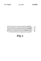
- FIG. 1 is a cross-sectional view of the bar code label construction in accordance with the present invention.
- FIG. 1 shows the printable coated film product of the present invention.
- Substrate 10 is a 2.0 mil film layer.
- Substrate 10 is coated on one side with both an opacifying coating 12 and a print receptive coating 14.
- Each of these coatings is a high modulus thermoset structural coating with good chemical and thermal resistance. Each, then, is particularly useful for thermally and chemically demanding applications.
- thermo demanding application is defined as one wherein temperatures may run as high as 300° C.
- a “chemically demanding” application it is meant that the structure is subject to applications such as wave solder, solder reflow, or vapor phase deposition are used or wherein etching acids such as sulfuric, chromic, or nitric acid or organic solvents such as toluene, MEK, and 1,1,1 trichloroethylene are used.
- etching acids such as sulfuric, chromic, or nitric acid or organic solvents such as toluene, MEK, and 1,1,1 trichloroethylene are used.
- printable it is meant that a thermal transfer ribbon dot matrix or laser printer, to name a few types of printers, will accept the image--that is, the image cannot be removed with tape.
- the print receptive coating 14 is receptive to ribbon and thermal transfer inks as well as laser copiers.
- the print receptive coating 14 is white for maximum contrast to black inks. It is also non-abrasive and anti-marking and is preferably applied at a thickness of 0.6 mil (dried).
- the print receptive coating 14 includes resin used as a binder.
- the resin is preferably an epoxy resin.
- epoxy resin it is meant a reaction product of Bisphenol and Epichlorohydrin.
- the epoxy resin is filled with boron nitride (BN) and titanium dioxide (TiO 2 ).
- Alternative suitable resins of the present invention include a polyurethane resin, an alkyd amine resin, a phenolic resin, a polyethersulfone resin, a polyamide-imide resin, and a polyketone resin.
- the resin of the preferred embodiment is bisphenol F epoxy resin (Shell 862).
- titanium dioxide alone was used as the only filler in the print receptive coating 14 to achieve whiteness. Titanium dioxide is commonly known as the most efficient pigment for white color and opacity. Using titanium dioxide as the only filler in the resin system, an opacity of over 90% was obtained at a coating thickness of 0.0003 inches. This coating, however, could not pass a "nickel rub” test, because TiO 2 is a hard irregular filler particle with abrasive characteristics. In an application involving a bar-code label, the label comes into contact with bar-code scanner tips, which are frequently nickel-chrome plated. Nickel-chrome oxide is black in color.
- Barium sulfate (BaSO 4 ). Barium sulfate has a rounded particle structure making it a non-abrasive material. Its crystalline structure, though, makes it more translucent than TiO 2 creating problems with opacity and color.
- boron nitride As a filler in the resin system. Such results are attributed to the morphology of boron nitride.
- the boron nitride particle shape is a platelet.
- the platelet shape of the boron nitride allows for the filler to cover a large surface area in relation to its size when it orients itself within the resin system; hence, its unique slip and opacity characteristics.
- boron nitride is much less abrasive than TiO 2 used alone. Further, it is superior to barium sulfate in terms of both opacity and color properties.
- ratios of TiO 2 /BN were tested to determine the optimum ratio providing both whiteness and opacity, yet non-abrasive.
- several grades of TiO 2 and BN were also evaluated. The optimum ratio was determined to be at about 90 wt. % BN to about 10 wt. % TiO 2 . Some marking was observed at 13 wt. % TiO 2 ; however, higher ratios of TiO 2 can be used at lower filler loadings.
- the filler to resin ratio was also optimized and found to be 45 percent by volume of filler to resin. At this ratio, the necessary whiteness level was achieved.
- the print receptive coating 14 also contains a reactive diluent to increase the ability of the epoxy resin to wet out the filler and allow the particles to lay flat. To improve mar resistance, the viscosity of the resin was reduced by providing the reactive diluent. The filler settles to the bottom leaving the top portion of the coating resin rich.
- Suitable diluents for use in the practice of the present invention include butyl glycidyl ether, Araldite RD-1,1,4 butanediol diglycidyl ether, Araldite RD-2, cresyl glycidyl ether, Araldite 023, phenyl glycidyl ether, glycidyl aniline. In the preferred embodiment, an alkylglycidyl ether (Shell Heloxy 8) is used.
- the print receptive coating 14 is also comprised of a curing agent.
- a curing agent Specific materials which can be used as the curing agent include aliphatic amines, cyclic amines, and cycloamines. Particular amines suitable for use in the practice of the present invention include monoethanol amine, diethanol amine, aminoethyl ethanolamide, aminoethyl piperazinone, ethylene diamine, diethyl aminopropylamine, and pentaethylene hexamine.
- a preferred curing agent is an aliphatic amine adduct curing agent (triethylene tetramine from Shell 3295).
- An antioxidant is also used in the print receptive coating 14 to improve the oxidative stability of the coating.
- the original prototypes did not have an antioxidant in the print receptive coating 14.
- the printable surface oxidized and turned brown.
- an antioxidant was added to the coating.
- Representative of the antioxidants that can be used in the present invention are Naugard 10 (Uniroyal), BNX 1076 (May 20), and BNX 1000 (May 20).
- the preferred antioxidant is Thiodiethylene bis (3,5-di-tert-butyl-4-hydroxyhydrocinnamate).
- the opacifying coating 12 shown in FIG. 1 is applied as an interlayer between the substrate 10 and the print receptive coating layer 14.
- the opacifying coating 12 is made up of an epoxy resin and a filler containing aluminum flake and titanium dioxide.
- the resin of the opacifying coating 12 is bisphenol A epoxy resin (Shell 828).
- Representative alternative resins for use in the opacifying coating 12 include a polyurethane resin, an alkyd amine resin, a phenolic resin, a polyethersulfone resin, and a polyamide-imide resin.
- the resin system selected for the opacifying coating 12 should preferably be identical to that selected for the print receptive coating 14. The systems do not have to be identical, though, as long as good adhesion is obtained between the layers.
- Aluminum flakes are also used as a filler in the opacifying coating 12, since aluminum has no light transmission. In place of aluminum flakes, nickel, tin, silver or other metal flakes could be used.
- Titanium dioxide is also used as a filler in the resin system of the opacifying layer 12 to decrease its contrast to the top printable coating.
- the thickness of the opacifying layer 12 is 0.2 ⁇ 0.05 mil.
- the opacifying layer 12 is preferably as thin as possible to reduce the overall cost of the coating and make the bar code label suitable from a marketing standpoint.
- the following films can be used: polyimide film; polyethersulfone film; polyetherketone film; polyethylene naphthalene film; polyester film; and polyetherimide film.
- the substrate 10 is a polyimide film, having a thickness of about 2 mil.
- the opposite side of substrate 10 is coated or thermoset onto acrylic PSA 16 by reverse roll coating.
- the acrylic PSA is #538m from H+N chemical and has a dry film thickness of 0.6 mil.
- the acrylic PSA 16 is laminated to a silicone coated release liner 18.
- the silicone coated release liner 18 is coated onto 55# super densified paper 20 in a separate production step by gravure on reverse roll coating.
- silane To hydrolyze silane, 10 lbs. isopropanol (IPA from Fish Chemical), 0.34 lbs. gamma aminopropyltrimethoxysilane (OSI A-1100), and 0.34 lbs. gamma glycidoxypropyltrimethoxysilane (OSI A-187) were added to a clean pail. The resultant silane solution was stirred for 20 minutes.
- IPA isopropanol
- OSI A-1100 0.34 lbs. gamma aminopropyltrimethoxysilane
- OSI A-187 0.34 lbs. gamma glycidoxypropyltrimethoxysilane
- the fillers for the resin system were prepared by weighing out 7.46 lbs. aluminum flake (Reynolds 30XD) and 26.92 lbs. titanium oxide (Tioxide RXLI) in a separate pail. The silane solution was then added to the fillers. Enough xylene (6.50 lbs.) (Fish Chemical) was then added to the pail to wet the fillers. The contents of the pail were stirred so that all of the powder was wetted out. The resultant filler slurry was allowed to stand for 30 minutes.
- the resultant fill/resin slurry was placed in a 55 gallon drum and mixed with 30.43 lbs. MEK (Fish Chemical) for approximately 20 minutes. 3.49 lbs. triethylenetetramine (Shell 3295) (used as the curing agent) were added to the filler/resin slurry to prepare the mixture for coating. The coating was mixed for 15 minutes at a high shear rate.
- silane To hydrolyze silane, 12.0 lbs. isopropanol (IPA from Fish Chemical) and 0.10 lbs. (45.63g) gamma aminopropyltriethoxysilane (OSI A-1100) were added to a clean pail. The resultant silane solution was stirred for 20 minutes.
- IPA isopropanol
- OSI A-1100 gamma aminopropyltriethoxysilane
- the fillers for the resin system were prepared by weighing out 11.38 lbs. boron nitride (Advanced Ceramics AC 6003) and 2.25 lbs. titanium dioxide (Tioxide RXLI) in a separate pail.
- the silane solution was added to the fillers.
- 48.0 lbs. MEK (Fish Chemical) were then added to the pail to wet the fillers.
- the contents of the pail were stirred so that all of the powder was completely wetted.
- the resultant filler slurry was allowed to stand for 30 minutes.
- the epoxy solution was then added to the filler slurry and ball milled for 24 hrs. 1.40 lbs. triethylenetetramine (Shell Epicure 3295) were then added to the 55 gallon drum to prepare the mixture for coating. The coating was mixed for 15 minutes at a high shear rate.
- the resultant print receptive coating had the formulation indicated below in TABLE II.
- Example II was repeated in an identical manner with the exceptions that a polyurethane resin system was substituted for the bisphenol F epoxy resin and a three roll mill was used to disburse the fillers in the resin system.
- the resultant print receptive coating had the formulation indicated below in TABLE III.
- Example II was repeated in an identical manner with the exceptions that an alkyd amine resin system was substituted for the bisphenol F epoxy resin and a three roll mill was used to disburse the fillers in the resin system.
- the resultant print receptive coating had the formulation indicated below in TABLE IV.
- Example II was repeated in an identical manner with the exceptions that a phenolic resin system was substituted for the bisphenol F epoxy resin and a three roll mill was used to disburse the fillers in the resin system.
- the resultant print receptive coating had the formulation indicated below in TABLE V.
- Example II was repeated in an identical manner with the exceptions that a polyethersulfone resin system was substituted for the bisphenol F epoxy resin and a three roll mill was used to disburse the fillers in the resin system.
- the resultant print receptive coating had the formulation indicated below in TABLE VI.
- Example II was repeated in an identical manner with the exceptions that a polyamide-imide resin system was substituted for the bisphenol F epoxy resin and a three roll mill was used to disburse the fillers in the resin system.
- the resultant print receptive coating had the formulation indicated below in TABLE VII.
- Example II was repeated in an identical manner with the exceptions that a polyketone resin system was substituted for the bisphenol F epoxy resin and a three roll mill was used to disburse the fillers in the resin system.
- the resultant print receptive coating had the formulation indicated below in Table VIII.
- Example I The coating formed in Example I was applied to a 2 mil polyimide film and was coated at a thickness of 0.20 mil (dry) using gravure coating.
- the resultant film and coating were drawn through an oven heated to 380° F. at 10 yards/minute.
- the coating itself saw a minimum temperature of 260° F. Once the coated film exited the oven, it was contacted with a heating hot can at 360° F. and wound into a roll.
- a 0.60 mil dried layer of the coating formed in Example II was applied to the rolled film using reverse roll coating.
- the film was drawn through an oven heated to 380° F. at 10 yards/minute.
- the second coating saw a minimum temperature of 260° F. Once the film coated with the first and second coatings exited the oven, it was contacted with a heating hot can at 360° F. and wound into a roll.
- the resultant film and coatings were placed in an oven at 50° C. overnight to fully cure the coatings.
- the resultant film and coatings were then further processed in a similar roll-to-roll process to apply a 0.0006 inch thick layer of a high temperature cross-linking acrylic pressure sensitive adhesive (PSA).
- PSA high temperature cross-linking acrylic pressure sensitive adhesive
- This construction was then slit to label printing equipment widths and subsequently kiss-cut through the label construction, but not through the silicone coated paper.
- the resultant film product was subjected to various quantitative and qualitative testing, including the following:
- NICKEL RUB Using a nickel, the film product was scratched across the surface of the coating. No visual dark mark was found to be present.
Abstract
Description
              TABLE I
______________________________________
SUPPLIER
        DESCRIPTION      ITEM     WEIGHT (%)
______________________________________
Shell   bisphenol A epoxy resin
                         Epon 828 13.96
Reynolds
        aluminum flake   30XD     7.46
Tioxide titanium dioxide RXLI     26.92
Shell   triethylenetetramine (cure
                         Epicure  3.49
        agent)           3295
OSI     gamma            A1100    0.34
        aminopropyltrimethoxysilane
OSI     gamma            A187     0.34
        glycidoxypropyltrimethoxy-
        silane
Kenrich titanium IV 2-propanolato
                         KR-TTS   0.56
Petrochem
Fish    solvent          MEK      30.43
Chemical
Fish    solvent          IPA      10.00
Chemical
Fish    solvent          Xylene   6.50
Chemical
______________________________________
 TOTAL SOLIDS: 49.64%
 100 lbs. total weight
              TABLE II
______________________________________
SUPPLIER
        DESCRIPTION     ITEM      WEIGHT (%)
______________________________________
Shell   bisphenol F epoxy resin
                        Epon 862  4.41
Shell   aliphatic epoxide
                        Heloxy 8  0.50
Shell   triethylenetetramine (cure
                        Epicure 3295
                                  1.40
        agent)
Advanced
        boron nitride   AC 6003   11.38
Ceramics
Tioxide titanium dioxide
                        RXLI      2.25
OSI     gamma           A1100     0.10
        aminopropyltriethoxysilane
Ciba-   hydroxyhydrocinnamate
                        Irganox 1035
                                  0.53
Geigy
Fish    solvent         MEK       68.00
Chemical
Fish    solvent         IPA       12.00
Chemical
______________________________________
 TOTAL SOLIDS: 19.93%
 100 lbs. total weight
              TABLE III
______________________________________
SUPPLIER DESCRIPTION  ITEM        WEIGHT (%)
______________________________________
Miles    polyesterpolyol
                      1300-75     9.06
Miles    aliphatic isocyanate
                      HL          5.62
Advanced boron nitride
                      AC6003      16.96
Ceramics
Tioxide  titanium dioxide
                      RXLI        3.35
Fish     solvent      MEK         58.50
Chemical
Fish     solvent      Ethyl Acetate
                                  6.50
Chemical
______________________________________
 TOTAL SOLIDS: 30.5%
              TABLE IV
______________________________________
SUPPLIER
        DESCRIPTION     ITEM      WEIGHT (%)
______________________________________
Morton  alkyd amine     21P2B     11.35
Morton  toluenesulfonic acid
                        Catalyst M
                                  0.45
Advanced
        boron nitride   AC6003    18.81
Ceramics
Tioxide titanium dioxide
                        RXLI      3.72
OSI     gamma           A1100     0.67
        aminopropyltriethoxysilane
Fish    solvent         MEK       65.00
Chemical
______________________________________
 TOTAL SOLIDS: 29.8%
              TABLE V
______________________________________
SUPPLIER DESCRIPTION    ITEM     WEIGHT (%)
______________________________________
Oxy      formaldhyde polymer
                        75-108   17.74
Chemical (methylon)
Advanced boron nitride  AC6003   17.74
Ceramics
Tioxide  titanium dioxide
                        RXLI     3.50
Fish     solvent        MEK      66.84
Chemical
______________________________________
 TOTAL SOLIDS: 33.2%
              TABLE VI
______________________________________
SUPPLIER   DESCRIPTION  ITEM    WEIGHT (%)
______________________________________
Amoco      polyethersulfone
                        Radel A 11.92
Advanced   boron nitride
                        AC6003  17.74
Ceramics
Tioxide    titanium dioxide
                        RXLI    3.50
Fish       solvent      MEK     66.84
Chemical
______________________________________
 TOTAL SOLIDS: 33.2%
              TABLE VII
______________________________________
SUPPLIER DESCRIPTION    ITEM     WEIGHT (%)
______________________________________
Amoco    polyamide-imide
                        A1-10    10.26
Advanced boron nitride  AC6003   17.77
Ceramics
Tioxide  titanium dioxide
                        RXLI     1.97
GAF      n-methyl pyrrolidone
                        NMP      70.00
______________________________________
 TOTAL SOLIDS 30.0%
              TABLE VIII
______________________________________
SUPPLIER DESCRIPTION   ITEM    WEIGHT (%)
______________________________________
Amoco    polyketone    Kadel   10.26
Advanced boron nitride AC6003  17.77
Ceramics
Tioxide  titanium dioxide
                       RXLI    1.97
Texaco   methyl ethyl ketone
                       MEK     70.00
______________________________________
 TOTAL SOLIDS: 30.0%
Claims (11)
Priority Applications (1)
| Application Number | Priority Date | Filing Date | Title |
|---|---|---|---|
| US08/914,826 US6120883A (en) | 1996-08-19 | 1997-08-19 | Computer printable top coating |
Applications Claiming Priority (2)
| Application Number | Priority Date | Filing Date | Title |
|---|---|---|---|
| US2413596P | 1996-08-19 | 1996-08-19 | |
| US08/914,826 US6120883A (en) | 1996-08-19 | 1997-08-19 | Computer printable top coating |
Publications (1)
| Publication Number | Publication Date |
|---|---|
| US6120883A true US6120883A (en) | 2000-09-19 |
Family
ID=26698091
Family Applications (1)
| Application Number | Title | Priority Date | Filing Date |
|---|---|---|---|
| US08/914,826 Expired - Fee Related US6120883A (en) | 1996-08-19 | 1997-08-19 | Computer printable top coating |
Country Status (1)
| Country | Link |
|---|---|
| US (1) | US6120883A (en) |
Cited By (4)
| Publication number | Priority date | Publication date | Assignee | Title |
|---|---|---|---|---|
| US20100330321A1 (en) * | 2009-06-25 | 2010-12-30 | Asia Electronic Material Co., Ltd | Cover layer for printed circuit board |
| WO2012054550A3 (en) * | 2010-10-20 | 2012-07-05 | Graphic Packaging International, Inc. | Heat transfer label for decorating a metal container |
| US20160315069A1 (en) * | 2013-12-18 | 2016-10-27 | Koninklijke Philips N.V. | Reflective solder mask layer for led phosphor package |
| US10400150B2 (en) * | 2012-02-29 | 2019-09-03 | Scg Chemicals Co., Ltd. | High emissivity coating compositions and manufacturing processes therefore |
Citations (4)
| Publication number | Priority date | Publication date | Assignee | Title |
|---|---|---|---|---|
| US5196228A (en) * | 1984-02-17 | 1993-03-23 | Mcdonnell Douglas Corporation | Laser resistant elastomer composition and use in coating process |
| US5514729A (en) * | 1993-11-17 | 1996-05-07 | Sophia Systems Co., Ltd. | Ultraviolet hardenable, solventless electrically conductive polymeric material |
| US5633086A (en) * | 1995-05-31 | 1997-05-27 | The United States Of America As Represented By The Secretary Of Commerce | Friction and wear resistant coating for titanium and its alloys |
| US5837352A (en) * | 1994-12-20 | 1998-11-17 | Kimberly-Clark Worldwide, Inc. | Mechanically compatibilized film/nonwoven laminate |
-
1997
- 1997-08-19 US US08/914,826 patent/US6120883A/en not_active Expired - Fee Related
Patent Citations (4)
| Publication number | Priority date | Publication date | Assignee | Title |
|---|---|---|---|---|
| US5196228A (en) * | 1984-02-17 | 1993-03-23 | Mcdonnell Douglas Corporation | Laser resistant elastomer composition and use in coating process |
| US5514729A (en) * | 1993-11-17 | 1996-05-07 | Sophia Systems Co., Ltd. | Ultraviolet hardenable, solventless electrically conductive polymeric material |
| US5837352A (en) * | 1994-12-20 | 1998-11-17 | Kimberly-Clark Worldwide, Inc. | Mechanically compatibilized film/nonwoven laminate |
| US5633086A (en) * | 1995-05-31 | 1997-05-27 | The United States Of America As Represented By The Secretary Of Commerce | Friction and wear resistant coating for titanium and its alloys |
Cited By (7)
| Publication number | Priority date | Publication date | Assignee | Title |
|---|---|---|---|---|
| US20100330321A1 (en) * | 2009-06-25 | 2010-12-30 | Asia Electronic Material Co., Ltd | Cover layer for printed circuit board |
| WO2012054550A3 (en) * | 2010-10-20 | 2012-07-05 | Graphic Packaging International, Inc. | Heat transfer label for decorating a metal container |
| US8709556B2 (en) | 2010-10-20 | 2014-04-29 | Mcc-Norwood, Llc | Heat transfer label for decorating a metal container |
| US10400150B2 (en) * | 2012-02-29 | 2019-09-03 | Scg Chemicals Co., Ltd. | High emissivity coating compositions and manufacturing processes therefore |
| US20160315069A1 (en) * | 2013-12-18 | 2016-10-27 | Koninklijke Philips N.V. | Reflective solder mask layer for led phosphor package |
| US10204887B2 (en) * | 2013-12-18 | 2019-02-12 | Lumileds Llc | Reflective solder mask layer for LED phosphor package |
| US11189601B2 (en) | 2013-12-18 | 2021-11-30 | Lumileds Llc | Reflective solder mask layer for LED phosphor package |
Similar Documents
| Publication | Publication Date | Title |
|---|---|---|
| KR102182815B1 (en) | Polyester-melamine coatings and labels including polyester-melamine coatings | |
| JP5389052B2 (en) | Method of manufacturing an electronic device with a glassy silicone hard coating as a release coating for printable electronics | |
| CA1336805C (en) | Coated laser printed labels | |
| US4686144A (en) | High performance printable coatings for identification devices | |
| US6120883A (en) | Computer printable top coating | |
| CA1300787C (en) | Epoxy fluorocarbon coating compositions and the process to make thesame | |
| US20180005550A1 (en) | Labels and Tags for High Temperature Applications | |
| JP6050897B2 (en) | Label and method for producing the label | |
| CN113631376A (en) | Release sheet | |
| CN114854320B (en) | Chip protective film, preparation method thereof and chip | |
| JP6824904B2 (en) | Print media, manufacturing methods of print media and printed matter | |
| JP2542499B2 (en) | OHP sheet for thermal transfer | |
| WO2011064859A1 (en) | Thermosetting protective solution for glass mask, and glass mask | |
| KR101085487B1 (en) | Conductive paste composite for screen printing and screen printing method using the same | |
| JP2799422B2 (en) | Heat resistant printing substrates and labels | |
| KR100403450B1 (en) | Adhesive Improvement of Polyester Films for Inkjet Printers | |
| JP2533386B2 (en) | Heat resistant printing substrate and label | |
| JP3054354B2 (en) | Heat resistant printing substrates and labels | |
| JP3532643B2 (en) | Heat resistant solvent resistant thermal transfer recording material | |
| JP2898395B2 (en) | Heat-resistant light-opaque label with print layer | |
| JPH107827A (en) | Surface-treated polyester film | |
| JPH082131A (en) | Thermal transfer image receiving material and white coating composition therefor | |
| WO2020027291A1 (en) | Multilayer body and method for producing epoxy resin sheet | |
| CN114274680A (en) | Resin carbon ribbon for soft label printing and preparation method thereof | |
| JP2989210B2 (en) | Heat resistant printing substrates and labels |
Legal Events
| Date | Code | Title | Description |
|---|---|---|---|
| AS | Assignment |
Owner name: FURON COMPANY, OHIO Free format text: ASSIGNMENT OF ASSIGNORS INTEREST;ASSIGNOR:ORLANDO, NANCY;REEL/FRAME:009751/0233 Effective date: 19980225 |
|
| AS | Assignment |
Owner name: FURON COMPANY, CALIFORNIA Free format text: ASSIGNMENT OF ASSIGNOR'S INTEREST PURSUANT TO PROFESSIONAL EMPLOYEE'S PATENT AND PROIPRIETARY INFORMATION AGREEMENT SIGNED BY GARY JAY LITMAN.;ASSIGNOR:LITMAN, GARY JAY;REEL/FRAME:011295/0956 Effective date: 19950203 |
|
| AS | Assignment |
Owner name: SAINT-GOBAIN PERFORMANCE PLASTICS CORPORATION, A C Free format text: MERGER AND CHANGE OF NAME;ASSIGNOR:FURON COMPANY, A CORP. OF CALIFORNIA;REEL/FRAME:011541/0358 Effective date: 19991231 |
|
| FEPP | Fee payment procedure |
Free format text: PAYOR NUMBER ASSIGNED (ORIGINAL EVENT CODE: ASPN); ENTITY STATUS OF PATENT OWNER: LARGE ENTITY |
|
| FPAY | Fee payment |
Year of fee payment: 4 |
|
| FPAY | Fee payment |
Year of fee payment: 8 |
|
| REMI | Maintenance fee reminder mailed | ||
| LAPS | Lapse for failure to pay maintenance fees | ||
| STCH | Information on status: patent discontinuation |
Free format text: PATENT EXPIRED DUE TO NONPAYMENT OF MAINTENANCE FEES UNDER 37 CFR 1.362 |
|
| FP | Lapsed due to failure to pay maintenance fee |
Effective date: 20120919 |