US6128459A - Color image forming apparatus and method of obtaining color images with decreased image positional deviation - Google Patents
Color image forming apparatus and method of obtaining color images with decreased image positional deviation Download PDFInfo
- Publication number
- US6128459A US6128459A US08/972,413 US97241397A US6128459A US 6128459 A US6128459 A US 6128459A US 97241397 A US97241397 A US 97241397A US 6128459 A US6128459 A US 6128459A
- Authority
- US
- United States
- Prior art keywords
- line
- detecting
- mark
- positional deviation
- color image
- Prior art date
- Legal status (The legal status is an assumption and is not a legal conclusion. Google has not performed a legal analysis and makes no representation as to the accuracy of the status listed.)
- Expired - Fee Related
Links
Images


Classifications
-
- G—PHYSICS
- G03—PHOTOGRAPHY; CINEMATOGRAPHY; ANALOGOUS TECHNIQUES USING WAVES OTHER THAN OPTICAL WAVES; ELECTROGRAPHY; HOLOGRAPHY
- G03G—ELECTROGRAPHY; ELECTROPHOTOGRAPHY; MAGNETOGRAPHY
- G03G15/00—Apparatus for electrographic processes using a charge pattern
- G03G15/01—Apparatus for electrographic processes using a charge pattern for producing multicoloured copies
- G03G15/0142—Structure of complete machines
- G03G15/0178—Structure of complete machines using more than one reusable electrographic recording member, e.g. one for every monocolour image
- G03G15/0194—Structure of complete machines using more than one reusable electrographic recording member, e.g. one for every monocolour image primary transfer to the final recording medium
-
- G—PHYSICS
- G03—PHOTOGRAPHY; CINEMATOGRAPHY; ANALOGOUS TECHNIQUES USING WAVES OTHER THAN OPTICAL WAVES; ELECTROGRAPHY; HOLOGRAPHY
- G03G—ELECTROGRAPHY; ELECTROPHOTOGRAPHY; MAGNETOGRAPHY
- G03G2215/00—Apparatus for electrophotographic processes
- G03G2215/01—Apparatus for electrophotographic processes for producing multicoloured copies
- G03G2215/0103—Plural electrographic recording members
- G03G2215/0119—Linear arrangement adjacent plural transfer points
- G03G2215/0138—Linear arrangement adjacent plural transfer points primary transfer to a recording medium carried by a transport belt
- G03G2215/0141—Linear arrangement adjacent plural transfer points primary transfer to a recording medium carried by a transport belt the linear arrangement being horizontal
-
- G—PHYSICS
- G03—PHOTOGRAPHY; CINEMATOGRAPHY; ANALOGOUS TECHNIQUES USING WAVES OTHER THAN OPTICAL WAVES; ELECTROGRAPHY; HOLOGRAPHY
- G03G—ELECTROGRAPHY; ELECTROPHOTOGRAPHY; MAGNETOGRAPHY
- G03G2215/00—Apparatus for electrophotographic processes
- G03G2215/01—Apparatus for electrophotographic processes for producing multicoloured copies
- G03G2215/0151—Apparatus for electrophotographic processes for producing multicoloured copies characterised by the technical problem
- G03G2215/0158—Colour registration
- G03G2215/0161—Generation of registration marks
Definitions
- the present invention relates to a color image forming apparatus and method of forming a color image using an electrophotographic process.
- a so-called tandem-type method is used in a color image forming apparatus in which a color image is obtained by transferring by superposition respective color images formed with an electrophotographic processing section of the apparatus onto a recording sheet.
- FIG. 1 is a side view of a color image forming apparatus of the tandem-type method.
- a sheet conveying path 4 is provided for guiding a transfer sheet 1, as a recording sheet, from a sheet feeding section 2 through a sheet discharging section 3 in the color image forming apparatus.
- the sheet conveying path 4 includes a conveying belt 7 that is movably positioned between a belt drive roller 5 that is rotated by drive power from a drive power source (not shown) and a belt driven roller 6 coupled to the drive power source.
- a drive power source not shown
- four electrophotographic processing sections 8Y, 8M, 8C, and 8K for yellow, magenta, cyan, and black are respectively disposed in order.
- These electrophotographic processing sections 8 respectively include a photoconductive drum 9, as a photoconductive element, that contacts the conveying belt 7, as well as a charging device 10, an exposing device 11, a developing device 12, a transferring device 13, and a photoconductive element cleaner 14 each being disposed in order around the photoconductive element 9.
- the conveying path 4 is provided with a fixing unit 15 at a position just after the conveying belt 7, as shown.
- the color image forming apparatus that has such a construction feeds an uppermost transfer sheet 1 from a sheet feeding section 2 towards the sheet conveying path 4, and is conveyed with the conveying belt 7.
- an image forming operation for each of the four colors is performed by each electrophotographic processing section 8, using electrophotographic processes, i.e., charging, exposing, developing, and transferring processes.
- a color toner image is transferred onto the transfer sheet 1, and fixed thereon by being heated and pressed with the fixing unit 15. This is a principle of image forming by the color image forming apparatus of the tandem-type method as shown in FIG. 1.
- FIG. 2 illustrates from a perspective view the conveying belt 7 and respective drums 9.
- a main scanning direction is indicated by a mark B
- a sub-scanning direction is indicated by a mark C.
- the present inventors recognized that this conventional apparatus has a shortcoming in that an alignment of each of the colors is difficult to achieve and maintain. Therefore, for example, a slight positional deviation often occurs when a user or a service engineer moves a part of the electrophotographic processing section 8 from a proper position when removing a jammed sheet or repairing the apparatus, and this slight positional deviation causes a color deviation between the respective colors.
- Image positional deviation detecting sensors 102 which include two CCD line sensors 101 (in FIG. 4), are positioned so as to face the conveying belt 7.
- Image positional deviation detecting marks 103 are formed on the conveying belt 7 by the electrophotographic processing section 8 before the image forming operation is performed.
- the detecting marks 103 are positioned in areas where the CCD line sensors 101 can read them such that an amount of image positional deviation corresponding to the electrophotographic processing sections 8Y, 8M, 8C, and 8K can then detected by reading the positional deviation detecting marks 103 by the CCD line sensors 101 as shown in FIG. 3.
- the image positional deviation detecting sensor 102 includes a light source 104 and a light collecting lens 105 for collecting and providing reflection light to the CCD line sensor 101, reflected by the conveying belt 7, which is emitted from the light source 104 as shown in FIG. 4.
- the image positional deviation detecting method disclosed in Japanese Laid-Open Patent Publication No. 6-18796/1994 has some problems in that parts costs are greater than desired due to the inclusion of the expensive CCD line sensor 102 or light collecting lens 105. Furthermore, focusing of the reflection light from the conveying belt 7 must be adjusted by the light collecting lens 105, and therefore the successful operation of the apparatus become troublesome.
- a device is described in Japanese Laid-Open Patent Publication No. 6-118735/1994 as detecting the color image positional deviation using an inexpensive reflection-type optical sensor 204 composed of a light source 201, and a slit 202, and a light accepting element 203.
- V-shaped image positional deviation detecting marks 205 are formed on the conveying belt 7, and a leading edge and a trailing edge thereof are detected with two reflection-type optical sensors 204, as shown in FIG. 6.
- a black electrophotographic processing section 8K FIG. 6
- magenta electrophotographic processing section 8M (FIG. 1) and a magenta electrophotographic processing section 8M (FIG. 1), two black lines K1 and K2 which compose each edge of the first V-shaped mark, two magenta lines M1 and M2 which compose each edge of the second V-shaped mark, a black line K3 which composes one edge of the third V-shaped mark, and a magenta line M3 which composes another edge of the third V-shaped mark are formed on the conveying belt 7, as shown.
- FIG. 7 shows an example in which the magenta electrophotographic processing section 8M deviates in a sub-scanning direction.
- an output signal from one side of the reflection-type optical sensor 204a (lower part of FIG. 7) is represented in FIG. 8(a), and another side of the reflection-type optical sensor 204b (upper part of FIG. 7) is represented by a diagram in FIG. 8(b).
- a time difference between pulses based on a signal of one side reflection-type optical sensor 204 is not constant ⁇ FIG.
- the image positional deviation detecting mark 205 is formed on the conveying belt 7 with an electrophotographic process, toner is randomly scattered at an edge part E of the image positional deviation detecting mark 205. As shown in FIG. 9, this scattering of toner gives rise to a problem in that a sharply contrasted output signal cannot be obtained by the reflection-type optical sensor 204. Namely, an output waveform from the reflection-type optical sensor 204 has a gentle slope as shown in FIG. 10 which increases the difficulty of detecting a leading edge and a trailing edge of the mark 205.
- An image positional deviation detecting mark formed on the conveying belt is detected with a single detecting device composed of a light source, a slit, and a light accepting element.
- the slit is constructed with a combination of slits that are oriented parallel with each other and provided with approximately a same width as that of the image positional deviation detecting mark.
- FIG. 1 is a side view showing an example of a prior-art color image forming apparatus of a tandem-type method
- FIG. 2 is a perspective view showing a conveying belt and a photoconductive element
- FIG. 3 is a perspective view showing the conveying belt, the photoconductive element, and a detecting sensor of a prior-art apparatus for experimenting with a color deviation preventing method
- FIG. 4 is a vertical sectional side view of the detecting sensor
- FIG. 5 is a vertical sectional side view of the reflection-type optical sensor
- FIG. 6 is a perspective view showing the conveying belt, the photoconductive element, and a detecting sensor of another prior-art apparatus for experimenting with a color deviation preventing method
- FIG. 7 is a top view showing an image positional deviation detecting mark formed on the conveying belt
- FIGS. 8a and 8b are timing charts showing pulse signals based on output signals of the reflection-type optical sensors, which is read from the image positional deviation detecting mark;
- FIG. 9 is an enlarged top view showing a portion of the image positional deviation detecting mark
- FIG. 10 is a diagram showing an output signal of the reflection-type optical sensor that is read from the image positional deviation mark
- FIG. 11 is a perspective view showing the conveying belt, the photoconductive element, and the detecting device showing a first embodiment of the present invention
- FIG. 12 is a top view showing a positional relation between the detecting device (reflection-type optical sensor) and the image positional deviation detecting mark;
- FIG. 13 is a top view illustrating an example occurrence of a color positional deviation with respect to FIG. 12;
- FIG. 14 is a timing diagram showing an example time occurrence of a mark signal based on the detecting signal of the detecting device (reflection-type optical detecting sensor);
- FIGS. 15(a) and 15(b) are top views showing respective relationships of respective parts of the mark when the slanting angle of the slanting line which composes the image positional deviation detecting mark is relatively small;
- FIGS. 16(a) and 16(b) are top views showing respective relationships of respective parts of the mark when the slanting angle of the slanting line which composes the image positional deviation detecting mark is at an angle of 45 degrees;
- FIGS. 17(a) and 17(b) are top views showing respective relationships of respective parts of the mark when the slanting angle of the slanting line which composes the image positional deviation detecting mark is relatively large;
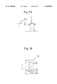
- FIG. 18 is a top view showing a variation of the image positional deviation detecting mark
- FIG. 19 is a vertical sectional elevation of a transmission-type optical sensor used for a variation detecting device
- FIGS. 20(a) and 20(b) are illustrations showing relationships between a width of a slit that is provided in the detecting device (reflection-type optical sensor, for FIG. 20(a)) and an output waveform of the detecting device (reflection-type optical sensor, for FIG. 20(b)) as a second embodiment of the present invention;
- FIGS. 21(a) and 21(b) are illustrations showing relationships between a width of a slit that is provided in the detecting device (reflection-type optical sensor, for FIG. 21(a)) and an output waveform of the detecting device (reflection-type optical sensor, for FIG. 21(b)) as a second embodiment of the present invention;
- FIGS. 22(a) and 22(b) are illustrations showing relationships between a width of a slit that is provided in the detecting device (reflection-type optical sensor, for FIG. 22(a) ⁇ and an output waveform of the detecting device (reflection-type optical sensor, for FIG. 22(b)) as a second embodiment of the present invention;
- FIGS. 23(a) and 23(b) are illustrations showing relationships between a width of a slit that is provided in the detecting device (reflection-type optical sensor, for FIG. 23(a) ⁇ and an output waveform of the detecting device (reflection-type optical sensor, for FIG. 23(b)) as a second embodiment of the present invention;
- FIG. 24(a) through 24(h) are top views showing examples of various kinds of shapes of the slit which can be provided in the detecting device (reflection-type optical sensor);
- FIG. 25 is a perspective view of the conveying belt, the photoconductive element, and the detecting device (reflection-type optical sensor) showing a third embodiment of the present invention.
- FIG. 26 is a top view showing a positional relationship between the detecting device (reflection-type optical sensor) and the image deviation detecting mark.
- FIGS. 11 through 17 A first embodiment of the present invention is explained in reference to FIGS. 11 through 17. Because common reference numerals represent the same elements previously explained in reference to FIGS. 1, 2, and 5, further explanation of these common elements is omitted.
- an apparatus and method for detecting an image positional deviation is shown in FIG. 11 for preventing a color image deviation induced by a positional deviation of respective of the electrophotographic processing sections 8 with photoconductive elements 9, as shown.
- FIG. 11 only one reflection-type optical sensor 204 is disposed on the conveying belt 7 and is used as a detecting device.
- An image positional deviation detecting mark 21 (hereinafter called a detection mark 21) is formed by the electrophotographic processing section 8 on the conveying belt 7 along an axis A l , as shown, before performing an image forming operation.
- a same pattern of marks of more than two colors including lines 21a i.e., 21Ka, 21Ma, . . .
- lines 21Ka and 21Kb are patterns formed with the black electrophotographic processing section 8K (FIG. 1)
- lines 21Ma and 21Mb are patterns formed with the magenta electrophotographic processing section 8M (FIG. 1).
- the reflection-type optical sensor 204 is the same as that described in FIG. 5, the explanation is omitted.
- FIG. 14 is a timing chart showing a signal based on a detecting signal of the reflection-type optical sensor 204.
- TK1, TK2, TM1, and TM2 show the respective times when the lines 21Ka, 21Kb, 21Ma, and 21Mb of the detection mark 21 pass by the reflection-type optical sensor 204 respectively.
- An inclination angle of ⁇ as shown in FIGS. 15a, 15b for example, corresponds with the angle between line 21b and 21a of the main scanning direction B.
- a color image positional deviation F in the sub-scanning direction C is obtained as follows:
- the color image positional deviation of the main scanning direction B and the sub-scanning direction C can be detected together with the amount of the color image positional deviation by mounting one inexpensive reflection-type optical sensor.
- the inclining angle of the line 21b that is formed at an inclination angle of 45° relative to the line 21a of the main scanning direction B ⁇ FIGS. 16(a) and 16(b) ⁇ notice that in FIGS. 15(b), 16(b) and 17(b) the line Z1Mb is offset in the main scanning direction by length L, but there is no such offset in FIGS. 15(b), 16(b) and 17(b).
- This offset seperates lines Z1K b and Z1M b along the axis A l , as shown, by the time differences t 2 and t' 2 .
- the reason why the above structure is adopted is that the larger the inclination angle ⁇ of the line 21b becomes (where ⁇ 2 in FIGS.
- FIG. 18 shows a modified detection mark 21, different than the detection mark shown in FIG. 11, that can be detected.
- the method by which the detection mark 21 of FIG. 18 can be detected by a transmission-type optical sensor, instead of the reflection-type optical sensor 204, is applicable as a modification of the present invention.
- This transmission-type optical sensor 301 has a construction, as shown in FIG. 19, in which light rays are radiated from the light source 302 onto the conveying belt 7 and transmitted therethrough, and thereafter accepted by the light-accepting element 304 via slit 303.
- the transmission-type optical sensor 301 is used, the detection mark 21 formed on the conveying belt 7 is surely detected, and the amount of the color image positional deviation based on the detected result from the detection mark 21 can be detected accurately.
- the light-accepting element of the reflection-type optical sensor 204 or the light accepting element 304 of the transmission-type optical sensor 301 may be provided as any one of a single element type or a multiple element type.
- FIGS. 20(a) through 23(b) The second embodiment of the present invention is explained in reference to FIGS. 20(a) through 23(b). Because same reference numerals have been used for common components of the first embodiment, an explanation of these common elements is omitted.
- FIGS. 20(a) through 23(b) A relationship between a width of the slit 202 which is provided in the reflection-type optical sensor 204 and an output waveform of the reflection-type optical sensor 204 is shown in FIGS. 20(a) through 23(b).
- a width of a line of the detection mark 21 is indicated with the label "h”.
- FIG. 20(a) shows a case in which the slit 202 has the width wider (H1) than that of the detection mark 21 width (H), and in this case, a peak level P at the output waveform of the reflection-type optical sensor 204 becomes flat ⁇ FIG. 20(b) ⁇ .
- FIG. 21(a) shows a case in which the slit 202 has approximately a same width (H2) as that of the detection mark 21, and in this case, a peak level P at the output waveform of the reflection-type optical sensor 204 becomes sharp ⁇ FIG. 21(b) ⁇ .
- FIG. 22(a) shows a case in which the width of the slit 202 (H3) is narrower than that of the detection mark 21, and in this case, a peak level P at the output waveform of the reflection-type optical sensor 204 becomes flat ⁇ FIG. 22(b) ⁇ . Further, FIG.
- the peak level P of the output waveform of the reflection-type optical sensor 204 has a predetermined pattern and thus by detecting the pattern (or a feature of the pattern) a position of the detection mark 21 may be accurately determined, particularly when the peak level P is as sharp as possible. Therefore, in accordance with FIGS. 20(a) through 23(b), it is understood that a condition to obtain the highest detection accuracy of the detection mark 21 with the reflection-type optical sensor 204 is that the slit 202 be positioned in parallel with the detection mark 21, and the width thereof be approximately the same as that of the detection mark 21.
- the slit 202 or a combination of parallel slits, to have a shape(s) being an approximately same width as that of the lines 21a and 21b of the detection mark 21.
- the slits 202 which are constructed with a combination of segments being parallel with each other and of approximately same width as that of the lines 21a and 21b of the detection mark 21 are proposed in this embodiment of the present invention.
- the shapes of the slits 202 are shown in detail in FIGS. 24(a) through 24(h).
- the third embodiment of the present invention is explained in reference to FIGS. 25 and 26.
- three reflection-type optical sensors 204 are mounted so as to face the conveying belt 7, and three detection marks 21, 22, and 23 are formed to be detected by the sensors 204.
- a magnification error and an inclination error in a main scanning direction B are detected at the same time.
- the present invention thus also includes a computer-based product which may be hosted on a storage medium and include instructions which can be used to program a computer to perform a process in accordance with the present invention.
- the storage medium can include, but is not limited to, any type of disk including floppy disk, optical disk, CD-ROMS, and magneto-optical disks, ROMS, RAMs, EPROMs, EEPROMs, flash memory, magnetic or optical cards, or any type of media suitable for storing electronic instructions.
Abstract
Description
E={(TM2-TM1)-(TK2-TK1)}V cotθ,
E={(TM2-TM1)-(TK2-TK1)}V (equation 1),
F={(TM1-TK1)-T0}V (equation 2.)
Claims (8)
F={(TM1-TK1)-TO}V F={(TM1-TK1)-TO}V F={(TM1-TK1)-TO}V Priority Applications (1)
| Application Number | Priority Date | Filing Date | Title |
|---|---|---|---|
| US09/617,243 US6282396B1 (en) | 1996-11-18 | 2000-07-14 | Color image forming apparatus and method of obtaining color images with decreased image positional deviation |
Applications Claiming Priority (4)
| Application Number | Priority Date | Filing Date | Title |
|---|---|---|---|
| JP8-306569 | 1996-11-18 | ||
| JP30656996 | 1996-11-18 | ||
| JP9-007746 | 1997-01-20 | ||
| JP9007746A JPH10198110A (en) | 1996-11-18 | 1997-01-20 | Color image forming method |
Related Child Applications (1)
| Application Number | Title | Priority Date | Filing Date |
|---|---|---|---|
| US09/617,243 Continuation US6282396B1 (en) | 1996-11-18 | 2000-07-14 | Color image forming apparatus and method of obtaining color images with decreased image positional deviation |
Publications (1)
| Publication Number | Publication Date |
|---|---|
| US6128459A true US6128459A (en) | 2000-10-03 |
Family
ID=26342096
Family Applications (2)
| Application Number | Title | Priority Date | Filing Date |
|---|---|---|---|
| US08/972,413 Expired - Fee Related US6128459A (en) | 1996-11-18 | 1997-11-18 | Color image forming apparatus and method of obtaining color images with decreased image positional deviation |
| US09/617,243 Expired - Lifetime US6282396B1 (en) | 1996-11-18 | 2000-07-14 | Color image forming apparatus and method of obtaining color images with decreased image positional deviation |
Family Applications After (1)
| Application Number | Title | Priority Date | Filing Date |
|---|---|---|---|
| US09/617,243 Expired - Lifetime US6282396B1 (en) | 1996-11-18 | 2000-07-14 | Color image forming apparatus and method of obtaining color images with decreased image positional deviation |
Country Status (2)
| Country | Link |
|---|---|
| US (2) | US6128459A (en) |
| JP (1) | JPH10198110A (en) |
Cited By (63)
| Publication number | Priority date | Publication date | Assignee | Title |
|---|---|---|---|---|
| US6275244B1 (en) | 2000-09-14 | 2001-08-14 | Xerox Corporation | Color printing image bearing member color registration system |
| US6348937B2 (en) * | 1999-03-01 | 2002-02-19 | Matsushita Electric Industrial Co., Ltd. | Color image forming apparatus |
| US6404449B1 (en) * | 1999-09-22 | 2002-06-11 | Konica Corporation | Color image forming apparatus performing an exposure scanning operation onto a photoreceptor by means of a laser beam reflected by a rotating mirror |
| US20020186985A1 (en) * | 2001-05-23 | 2002-12-12 | Takatsugu Fujishiro | Image carrier and damping member therefor |
| US6507720B2 (en) | 2000-07-21 | 2003-01-14 | Ricoh Company, Ltd. | Color image forming apparatus and toner replenishing apparatus each including plural toner containers received in receiving member of setting part and toner containers therefor |
| US6526246B2 (en) | 2000-07-31 | 2003-02-25 | Ricoh Company, Ltd. | Powder replenishing device, powder conveying device, developing apparatus using the same powder replenishing device or powder conveying device, and image forming apparatus using the same powder replenishing device or powder conveying device |
| US20030038968A1 (en) * | 2001-08-27 | 2003-02-27 | Hisanori Kawaura | Image forming apparatus, program updating method and recording medium |
| US20030044185A1 (en) * | 2001-08-27 | 2003-03-06 | Hisanori Kawaura | Image forming apparatus, program updating method and recording medium |
| US6542707B2 (en) | 2000-11-13 | 2003-04-01 | Ricoh Co., Ltd. | Method and apparatus for image forming capable of effectively transferring various kinds of powder |
| US20030068180A1 (en) * | 2001-10-09 | 2003-04-10 | Canon Kabushiki Kaisha | Image forming apparatus |
| US6567637B2 (en) | 2000-02-17 | 2003-05-20 | Ricoh Company, Ltd. | Apparatus and method for replenishing a developing device with toner while suppressing toner remaining |
| US6567643B2 (en) | 2000-09-27 | 2003-05-20 | Ricoh Company, Ltd. | Apparatuses for color image formation, tandem color image formation and image formation |
| US6571076B2 (en) | 2000-03-10 | 2003-05-27 | Ricoh Company, Ltd. | Image forming apparatus and toner container therefor |
| US6573918B2 (en) | 2000-08-22 | 2003-06-03 | Ricoh Company, Ltd. | Image forming apparatus having a plurality of image data interfaces |
| US6573919B2 (en) * | 2001-07-31 | 2003-06-03 | Hewlett-Packard Development Company L.P. | Method and apparatus for alignment of image planes |
| US6587137B2 (en) | 2000-08-11 | 2003-07-01 | Ricoh Company, Ltd. | Light beam scanning device |
| US6591077B2 (en) | 2000-05-08 | 2003-07-08 | Ricoh Company, Ltd. | Image forming apparatus and toner container therefor |
| US6597883B2 (en) | 2001-02-13 | 2003-07-22 | Ricoh Company, Ltd. | Powder pump capable of effectively conveying powder and image forming apparatus using powder pump |
| US6608984B1 (en) | 1999-04-23 | 2003-08-19 | Ricoh Company, Ltd. | Image forming method and apparatus using developer carrier pressed into engagement with image carrier |
| US6608981B2 (en) | 2000-06-05 | 2003-08-19 | Ricoh Company, Ltd. | Image forming apparatus having common guide members for detachably attaching a developing unit and a carrier unit |
| US6628908B2 (en) | 2000-09-28 | 2003-09-30 | Ricoh Company, Ltd | Toner supply unit and image forming apparatus |
| US6628915B2 (en) | 2001-10-30 | 2003-09-30 | Ricoh Company, Ltd. | Developer container for an image forming apparatus |
| US6628913B2 (en) | 2000-08-31 | 2003-09-30 | Ricoh Company, Ltd. | Method and apparatus for replenishing developer with a flexible powder container |
| US20030189610A1 (en) * | 2002-04-08 | 2003-10-09 | Samuel Darby | Certified proofing |
| US6644236B2 (en) | 2000-03-16 | 2003-11-11 | Ricoh Company, Ltd. | Deterioration indicator and a product having the same |
| US6693654B2 (en) | 2001-09-14 | 2004-02-17 | Ricoh Company, Limited | Color image formation apparatus and method including three alignment sensors and density adjustment sensor |
| US20040041896A1 (en) * | 2002-09-04 | 2004-03-04 | Tadashi Shinohara | Image forming apparatus |
| US6707480B2 (en) | 2001-03-23 | 2004-03-16 | Ricoh Company, Ltd. | Image formation unit including stored performance information |
| US6711364B2 (en) | 2001-09-21 | 2004-03-23 | Ricoh Company, Ltd. | Color image forming apparatus |
| US6714224B2 (en) | 2001-01-10 | 2004-03-30 | Ricoh Company, Ltd. | Method and apparatus for image forming capable of effectively performing color image position adjustment |
| US20040067077A1 (en) * | 2001-01-31 | 2004-04-08 | Kazuhisa Sudo | Toner container and image forming apparatus using the same |
| US6754462B2 (en) | 2001-02-13 | 2004-06-22 | Ricoh Company, Ltd. | Latent image carrier and image forming apparatus having a noise and deformation preventing member |
| US20040161261A1 (en) * | 2002-02-15 | 2004-08-19 | Nobuo Kasahara | Image forming apparatus including developing device and developer containing device |
| US6785496B2 (en) | 2001-05-24 | 2004-08-31 | Ricoh Company, Ltd. | Developer container, developing conveying device and image forming apparatus using the same |
| US20040179866A1 (en) * | 2002-12-18 | 2004-09-16 | Satoshi Muramatsu | Powder discharging device and image forming apparatus using the same |
| US6829465B2 (en) | 2001-01-10 | 2004-12-07 | Ricoh Company, Ltd | Method and apparatus for image forming capable of effectively performing color displacement detection |
| US20050009351A1 (en) * | 2003-07-09 | 2005-01-13 | Toshiyuki Takahashi | Image forming apparatus, program and positional error correction method |
| US20050007904A1 (en) * | 2003-05-12 | 2005-01-13 | Yoshiyuki Ishiyama | Tilt control method, program, recording medium, and optical disk drive |
| US20050041990A1 (en) * | 2003-08-22 | 2005-02-24 | Mitsugu Sugiyama | Method, system and software program for correcting positional color misalignment |
| US20050042001A1 (en) * | 2003-07-18 | 2005-02-24 | Tadashi Shinohara | Offset preventing color image forming apparatus |
| US20050053388A1 (en) * | 2003-07-18 | 2005-03-10 | Masato Yokoyama | Method and apparatus for image forming capable of effectively reducing unevenness of density and color displacement of images |
| US20050085945A1 (en) * | 2003-08-29 | 2005-04-21 | Toshiyuki Andoh | Belt driving controller, process cartridge, and image forming apparatus |
| US20050088505A1 (en) * | 2003-08-28 | 2005-04-28 | Tadashi Shinohara | Image forming apparatus, image forming method, and computer product |
| US20050089347A1 (en) * | 2003-09-18 | 2005-04-28 | Satoshi Muramatsu | Developer container, developer supplying unit, and image forming apparatus |
| US20050095037A1 (en) * | 2003-09-18 | 2005-05-05 | Takayuki Koike | Developing apparatus for image forming apparatus |
| US6909516B1 (en) | 2000-10-20 | 2005-06-21 | Xerox Corporation | Two dimensional surface motion sensing system using registration marks and linear array sensor |
| US6973283B2 (en) | 2000-07-14 | 2005-12-06 | Ricoh Company, Ltd. | Color image forming apparatus, and toner replenishing apparatus |
| US7032988B2 (en) | 2002-04-08 | 2006-04-25 | Kodak Graphic Communications Canada Company | Certified proofing |
| US7043179B2 (en) | 2003-06-27 | 2006-05-09 | Ricoh Company, Ltd. | Toner replenishing device with timing control of toner replenishing device |
| US20060164497A1 (en) * | 2005-01-27 | 2006-07-27 | Tadashi Shinohara | Needless detection performance correction suppressing image forming apparatus |
| US20070025779A1 (en) * | 2005-08-01 | 2007-02-01 | Tadashi Shinohara | Color image forming device |
| US20070097202A1 (en) * | 2005-11-01 | 2007-05-03 | Tadashi Shinohara | Device and method for controlling timing for starting image formation, and an image forming apparatus using such device and method |
| US20070115509A1 (en) * | 2005-11-07 | 2007-05-24 | Tadashi Shinohara | Control circuit and image forming apparatus controlled by software and hardware |
| US20070122210A1 (en) * | 2005-11-30 | 2007-05-31 | Kazuyuki Sato | Image forming device, image formation operation correcting method, and image formation operation correcting program |
| US20070140721A1 (en) * | 2005-11-30 | 2007-06-21 | Tadashi Shinohara | Method and apparatus for color image forming capable of effectively forming a quality color image |
| US20080075476A1 (en) * | 2006-09-22 | 2008-03-27 | Yasushi Nakazato | Image forming apparatus |
| US20080181634A1 (en) * | 2007-01-25 | 2008-07-31 | Izumi Kinoshita | Image forming apparatus with accurate correction of color misalignment |
| US20080292370A1 (en) * | 2007-05-25 | 2008-11-27 | Brother Kogyo Kabushiki Kaisha | Image Forming Apparatus |
| US20110150508A1 (en) * | 2009-12-21 | 2011-06-23 | Canon Kabushiki Kaisha | Image information detecting apparatus |
| US8585537B2 (en) | 2010-03-18 | 2013-11-19 | Ricoh Company, Limited | Driving device and image forming apparatus |
| US8588651B2 (en) | 2010-05-25 | 2013-11-19 | Ricoh Company, Ltd. | Rotary drive device with a planetary gear mechanism to drive a rotary body, and image forming apparatus including the same |
| US9201331B2 (en) | 2012-09-13 | 2015-12-01 | Ricoh Company, Limited | Image forming apparatus, image correcting method, computer readable storage medium, image correction unit and image forming system |
| US9703248B2 (en) * | 2014-05-16 | 2017-07-11 | Ricoh Company, Ltd. | Curling detection device, image forming apparatus, curling detection method, image adjustment method, recording medium storing a curling detection program, and recording medium storing an image adjustment program |
Families Citing this family (20)
| Publication number | Priority date | Publication date | Assignee | Title |
|---|---|---|---|---|
| JP3079076B2 (en) * | 1997-03-19 | 2000-08-21 | 富士通株式会社 | Image forming device |
| KR100313868B1 (en) * | 1998-11-18 | 2002-04-17 | 윤종용 | Optical scanning system of the printing press |
| KR100313867B1 (en) * | 1998-11-18 | 2002-04-17 | 윤종용 | Gwangju Unit Alignment Adjustment Device of Printing Machine |
| EP1048474B1 (en) * | 1999-04-28 | 2003-09-10 | Konica Corporation | Image exposure apparatus |
| JP2001166553A (en) | 1999-12-13 | 2001-06-22 | Ricoh Co Ltd | Color image forming device |
| JP4659182B2 (en) * | 2000-07-13 | 2011-03-30 | キヤノン株式会社 | Image forming apparatus |
| DE60130993T3 (en) * | 2000-07-18 | 2013-08-29 | Coloplast A/S | WOUND DRESSING |
| DE10141035A1 (en) * | 2001-08-22 | 2003-03-20 | Nexpress Solutions Llc | Method and printing machine for determining register errors |
| JP2003330218A (en) * | 2002-05-17 | 2003-11-19 | Ricoh Co Ltd | Toner, toner carrying apparatus and image forming apparatus |
| US7542703B2 (en) * | 2002-05-20 | 2009-06-02 | Ricoh Company, Ltd. | Developing device replenishing a toner or a carrier of a two-ingredient type developer and image forming apparatus including the developing device |
| JP3684212B2 (en) | 2002-06-05 | 2005-08-17 | 株式会社リコー | Volume reduction method for developer container, developer supply device, and image forming apparatus |
| JP4091899B2 (en) * | 2002-12-20 | 2008-05-28 | 株式会社リコー | Belt drive |
| US7257358B2 (en) * | 2003-12-19 | 2007-08-14 | Lexmark International, Inc. | Method and apparatus for detecting registration errors in an image forming device |
| JP4222259B2 (en) * | 2004-06-02 | 2009-02-12 | コニカミノルタビジネステクノロジーズ株式会社 | Image forming apparatus |
| JP4342506B2 (en) * | 2005-11-14 | 2009-10-14 | シャープ株式会社 | Image forming apparatus |
| JP4966025B2 (en) * | 2007-01-11 | 2012-07-04 | 株式会社リコー | Image forming method and image forming apparatus |
| JP5481863B2 (en) * | 2008-01-28 | 2014-04-23 | 株式会社リコー | Position shift amount detection device, position shift amount detection method, and position shift amount detection program |
| JP5181753B2 (en) * | 2008-03-18 | 2013-04-10 | 株式会社リコー | Color image forming apparatus, misregistration correction method, misregistration correction program, and recording medium |
| JP5137677B2 (en) * | 2008-04-30 | 2013-02-06 | キヤノン株式会社 | Color image forming apparatus |
| JP5200844B2 (en) * | 2008-10-10 | 2013-06-05 | 富士ゼロックス株式会社 | Image forming apparatus |
Citations (7)
| Publication number | Priority date | Publication date | Assignee | Title |
|---|---|---|---|---|
| US4908661A (en) * | 1987-11-27 | 1990-03-13 | Ricoh Company, Ltd. | Holder device for handling an image carrier of an image forming apparatus |
| US5008711A (en) * | 1987-04-23 | 1991-04-16 | Ricoh Company, Ltd. | Image forming apparatus |
| JPH0618796A (en) * | 1992-06-30 | 1994-01-28 | Canon Inc | Image forming device and scanning optical device |
| JPH06118735A (en) * | 1992-06-16 | 1994-04-28 | Xerox Corp | Positioning system for color picture output terminal |
| US5384592A (en) * | 1992-11-16 | 1995-01-24 | Xerox Corporation | Method and apparatus for tandem color registration control |
| US5464200A (en) * | 1993-04-15 | 1995-11-07 | Ricoh Company, Ltd. | Sheet storing device with locking bins |
| US5854958A (en) * | 1995-04-05 | 1998-12-29 | Kabushiki Kaisha Toshiba | Image forming apparatus having test patterns for correcting color discrepancy |
Family Cites Families (1)
| Publication number | Priority date | Publication date | Assignee | Title |
|---|---|---|---|---|
| US5828926A (en) | 1995-08-17 | 1998-10-27 | Ricoh Company, Ltd. | Registration control for an image forming apparatus having an intermediate transfer belt |
-
1997
- 1997-01-20 JP JP9007746A patent/JPH10198110A/en active Pending
- 1997-11-18 US US08/972,413 patent/US6128459A/en not_active Expired - Fee Related
-
2000
- 2000-07-14 US US09/617,243 patent/US6282396B1/en not_active Expired - Lifetime
Patent Citations (7)
| Publication number | Priority date | Publication date | Assignee | Title |
|---|---|---|---|---|
| US5008711A (en) * | 1987-04-23 | 1991-04-16 | Ricoh Company, Ltd. | Image forming apparatus |
| US4908661A (en) * | 1987-11-27 | 1990-03-13 | Ricoh Company, Ltd. | Holder device for handling an image carrier of an image forming apparatus |
| JPH06118735A (en) * | 1992-06-16 | 1994-04-28 | Xerox Corp | Positioning system for color picture output terminal |
| JPH0618796A (en) * | 1992-06-30 | 1994-01-28 | Canon Inc | Image forming device and scanning optical device |
| US5384592A (en) * | 1992-11-16 | 1995-01-24 | Xerox Corporation | Method and apparatus for tandem color registration control |
| US5464200A (en) * | 1993-04-15 | 1995-11-07 | Ricoh Company, Ltd. | Sheet storing device with locking bins |
| US5854958A (en) * | 1995-04-05 | 1998-12-29 | Kabushiki Kaisha Toshiba | Image forming apparatus having test patterns for correcting color discrepancy |
Cited By (120)
| Publication number | Priority date | Publication date | Assignee | Title |
|---|---|---|---|---|
| US6348937B2 (en) * | 1999-03-01 | 2002-02-19 | Matsushita Electric Industrial Co., Ltd. | Color image forming apparatus |
| US6608984B1 (en) | 1999-04-23 | 2003-08-19 | Ricoh Company, Ltd. | Image forming method and apparatus using developer carrier pressed into engagement with image carrier |
| US6404449B1 (en) * | 1999-09-22 | 2002-06-11 | Konica Corporation | Color image forming apparatus performing an exposure scanning operation onto a photoreceptor by means of a laser beam reflected by a rotating mirror |
| US6748190B2 (en) | 2000-02-17 | 2004-06-08 | Ricoh Company, Ltd. | Apparatus and method for replenishing a developing device with toner while suppressing toner remaining |
| US7289748B2 (en) | 2000-02-17 | 2007-10-30 | Ricoh Company, Ltd. | Apparatus and method for replenishing a developing device with toner while suppressing toner remaining |
| US7218880B2 (en) | 2000-02-17 | 2007-05-15 | Ricoh Company, Ltd. | Apparatus and method for replenishing a developing device with toner while suppressing toner remaining |
| US6567637B2 (en) | 2000-02-17 | 2003-05-20 | Ricoh Company, Ltd. | Apparatus and method for replenishing a developing device with toner while suppressing toner remaining |
| US6571076B2 (en) | 2000-03-10 | 2003-05-27 | Ricoh Company, Ltd. | Image forming apparatus and toner container therefor |
| US6644236B2 (en) | 2000-03-16 | 2003-11-11 | Ricoh Company, Ltd. | Deterioration indicator and a product having the same |
| US6591077B2 (en) | 2000-05-08 | 2003-07-08 | Ricoh Company, Ltd. | Image forming apparatus and toner container therefor |
| US6608981B2 (en) | 2000-06-05 | 2003-08-19 | Ricoh Company, Ltd. | Image forming apparatus having common guide members for detachably attaching a developing unit and a carrier unit |
| US6973283B2 (en) | 2000-07-14 | 2005-12-06 | Ricoh Company, Ltd. | Color image forming apparatus, and toner replenishing apparatus |
| US6507720B2 (en) | 2000-07-21 | 2003-01-14 | Ricoh Company, Ltd. | Color image forming apparatus and toner replenishing apparatus each including plural toner containers received in receiving member of setting part and toner containers therefor |
| US6526246B2 (en) | 2000-07-31 | 2003-02-25 | Ricoh Company, Ltd. | Powder replenishing device, powder conveying device, developing apparatus using the same powder replenishing device or powder conveying device, and image forming apparatus using the same powder replenishing device or powder conveying device |
| US6587137B2 (en) | 2000-08-11 | 2003-07-01 | Ricoh Company, Ltd. | Light beam scanning device |
| US6573918B2 (en) | 2000-08-22 | 2003-06-03 | Ricoh Company, Ltd. | Image forming apparatus having a plurality of image data interfaces |
| US6628913B2 (en) | 2000-08-31 | 2003-09-30 | Ricoh Company, Ltd. | Method and apparatus for replenishing developer with a flexible powder container |
| US6275244B1 (en) | 2000-09-14 | 2001-08-14 | Xerox Corporation | Color printing image bearing member color registration system |
| US6567643B2 (en) | 2000-09-27 | 2003-05-20 | Ricoh Company, Ltd. | Apparatuses for color image formation, tandem color image formation and image formation |
| US7209689B2 (en) | 2000-09-28 | 2007-04-24 | Ricoh Company, Ltd. | Toner supply unit and image forming apparatus |
| US6628908B2 (en) | 2000-09-28 | 2003-09-30 | Ricoh Company, Ltd | Toner supply unit and image forming apparatus |
| US7088945B2 (en) | 2000-09-28 | 2006-08-08 | Ricoh Company, Ltd. | Toner supply unit and image forming apparatus |
| US7130558B2 (en) | 2000-09-28 | 2006-10-31 | Ricoh Company, Ltd | Toner supply unit and image forming apparatus |
| US7356290B2 (en) | 2000-09-28 | 2008-04-08 | Ricoh Company, Ltd. | Toner supply unit and image forming apparatus |
| US20050169673A1 (en) * | 2000-09-28 | 2005-08-04 | Junichi Matsumoto | Toner supply unit and image forming apparatus |
| US20040197119A1 (en) * | 2000-09-28 | 2004-10-07 | Junichi Matsumoto | Toner supply unit and image forming apparatus |
| US7542697B2 (en) | 2000-09-28 | 2009-06-02 | Ricoh Company, Ltd | Toner supply unit and image forming apparatus |
| US6909516B1 (en) | 2000-10-20 | 2005-06-21 | Xerox Corporation | Two dimensional surface motion sensing system using registration marks and linear array sensor |
| US6542707B2 (en) | 2000-11-13 | 2003-04-01 | Ricoh Co., Ltd. | Method and apparatus for image forming capable of effectively transferring various kinds of powder |
| US6829465B2 (en) | 2001-01-10 | 2004-12-07 | Ricoh Company, Ltd | Method and apparatus for image forming capable of effectively performing color displacement detection |
| US6714224B2 (en) | 2001-01-10 | 2004-03-30 | Ricoh Company, Ltd. | Method and apparatus for image forming capable of effectively performing color image position adjustment |
| US20040067077A1 (en) * | 2001-01-31 | 2004-04-08 | Kazuhisa Sudo | Toner container and image forming apparatus using the same |
| US7162188B2 (en) | 2001-01-31 | 2007-01-09 | Ricoh Company, Ltd. | Toner container and image forming apparatus using the same |
| US7158742B2 (en) | 2001-01-31 | 2007-01-02 | Ricoh Company, Ltd. | Toner container and image forming apparatus using the same |
| US7110704B2 (en) | 2001-01-31 | 2006-09-19 | Ricoh Company, Ltd. | Toner container and image forming apparatus using the same |
| US20040146319A1 (en) * | 2001-01-31 | 2004-07-29 | Kazuhisa Sudo | Toner container and image forming apparatus using the same |
| US6813460B2 (en) | 2001-01-31 | 2004-11-02 | Ricoh Company, Ltd. | Toner container and image forming apparatus using the same |
| US7209687B2 (en) | 2001-01-31 | 2007-04-24 | Ricoh Company, Ltd. | Toner container and image forming apparatus using the same |
| US7130567B2 (en) | 2001-01-31 | 2006-10-31 | Ricoh Company, Ltd. | Toner container and image forming apparatus using the same |
| US7412191B2 (en) | 2001-01-31 | 2008-08-12 | Ricoh Company, Ltd. | Toner container and image forming apparatus using the same |
| US6597883B2 (en) | 2001-02-13 | 2003-07-22 | Ricoh Company, Ltd. | Powder pump capable of effectively conveying powder and image forming apparatus using powder pump |
| US6754462B2 (en) | 2001-02-13 | 2004-06-22 | Ricoh Company, Ltd. | Latent image carrier and image forming apparatus having a noise and deformation preventing member |
| US6707480B2 (en) | 2001-03-23 | 2004-03-16 | Ricoh Company, Ltd. | Image formation unit including stored performance information |
| US20020186985A1 (en) * | 2001-05-23 | 2002-12-12 | Takatsugu Fujishiro | Image carrier and damping member therefor |
| US6757508B2 (en) | 2001-05-23 | 2004-06-29 | Ricoh Company, Ltd. | Image carrier and damping member therefor |
| US6785496B2 (en) | 2001-05-24 | 2004-08-31 | Ricoh Company, Ltd. | Developer container, developing conveying device and image forming apparatus using the same |
| US6573919B2 (en) * | 2001-07-31 | 2003-06-03 | Hewlett-Packard Development Company L.P. | Method and apparatus for alignment of image planes |
| US7725890B2 (en) | 2001-08-27 | 2010-05-25 | Ricoh Company, Ltd. | Image forming apparatus including a device that updates stored program based on updating data which is selected based on program that is started or startable |
| US6952535B2 (en) | 2001-08-27 | 2005-10-04 | Ricoh Company, Ltd. | Image forming apparatus, program updating method and recording medium |
| US20030038968A1 (en) * | 2001-08-27 | 2003-02-27 | Hisanori Kawaura | Image forming apparatus, program updating method and recording medium |
| US8856773B2 (en) | 2001-08-27 | 2014-10-07 | Ricoh Company, Ltd. | Image forming apparatus including a device that updates stored program based on updating data which is selected based on program that is started or startable |
| US20100149596A1 (en) * | 2001-08-27 | 2010-06-17 | Hisanori Kawaura | Image forming apparatus including a device that updates stored program based on updating data which is selected based on program that is started or startable |
| US7327488B2 (en) | 2001-08-27 | 2008-02-05 | Ricoh Company, Ltd. | Image forming apparatus, program updating method and recording medium |
| US8453137B2 (en) | 2001-08-27 | 2013-05-28 | Ricoh Company, Ltd. | Image forming apparatus including a device that updates stored program based on updating data which is selected based on program that is started or startable |
| US10277767B2 (en) | 2001-08-27 | 2019-04-30 | Ricoh Company, Ltd. | Image forming apparatus including a device that updates stored program based on updating data which is selected based on program that is started or startable |
| US20050100353A1 (en) * | 2001-08-27 | 2005-05-12 | Hisanori Kawaura | Image forming apparatus including a device that updates stored program based on updating data which is selected based on program that is started or startable |
| US20040213588A1 (en) * | 2001-08-27 | 2004-10-28 | Hisanori Kawaura | Image forming apparatus, program updating method and recording medium |
| US6915085B2 (en) | 2001-08-27 | 2005-07-05 | Ricoh Company, Ltd. | Image forming apparatus including a device that updates stored program based on updating data which is selected based on program of control service that is started or startable, program updating method and computer-readable recording medium |
| US9497347B2 (en) | 2001-08-27 | 2016-11-15 | Ricoh Company, Ltd. | Image forming apparatus including a device that updates stored program based on updating data which is selected based on program that is started or startable |
| US20030044185A1 (en) * | 2001-08-27 | 2003-03-06 | Hisanori Kawaura | Image forming apparatus, program updating method and recording medium |
| US6693654B2 (en) | 2001-09-14 | 2004-02-17 | Ricoh Company, Limited | Color image formation apparatus and method including three alignment sensors and density adjustment sensor |
| US6711364B2 (en) | 2001-09-21 | 2004-03-23 | Ricoh Company, Ltd. | Color image forming apparatus |
| US6701117B2 (en) * | 2001-10-09 | 2004-03-02 | Canon Kabushiki Kaisha | Image forming apparatus |
| US20030068180A1 (en) * | 2001-10-09 | 2003-04-10 | Canon Kabushiki Kaisha | Image forming apparatus |
| US20040197121A1 (en) * | 2001-10-30 | 2004-10-07 | Satoshi Muramatsu | Developer container for an image forming apparatus |
| US20050158083A1 (en) * | 2001-10-30 | 2005-07-21 | Satoshi Muramatsu | Developer container for an image forming apparatus |
| US7085522B2 (en) | 2001-10-30 | 2006-08-01 | Ricoh Company, Ltd. | Developer container for an image forming apparatus |
| US6628915B2 (en) | 2001-10-30 | 2003-09-30 | Ricoh Company, Ltd. | Developer container for an image forming apparatus |
| US7346299B2 (en) | 2001-10-30 | 2008-03-18 | Ricoh Company, Ltd. | Developer container for an image forming apparatus |
| US6882812B2 (en) | 2002-02-15 | 2005-04-19 | Ricoh Company, Ltd. | Image forming apparatus including developing device and developer containing device |
| US20040161261A1 (en) * | 2002-02-15 | 2004-08-19 | Nobuo Kasahara | Image forming apparatus including developing device and developer containing device |
| US7032988B2 (en) | 2002-04-08 | 2006-04-25 | Kodak Graphic Communications Canada Company | Certified proofing |
| US6793310B2 (en) | 2002-04-08 | 2004-09-21 | Creo Americas, Inc. | Certified proofing |
| US20030189610A1 (en) * | 2002-04-08 | 2003-10-09 | Samuel Darby | Certified proofing |
| US7417757B2 (en) | 2002-09-04 | 2008-08-26 | Ricoh Company, Ltd. | Image forming apparatus |
| US20040041896A1 (en) * | 2002-09-04 | 2004-03-04 | Tadashi Shinohara | Image forming apparatus |
| US20040179866A1 (en) * | 2002-12-18 | 2004-09-16 | Satoshi Muramatsu | Powder discharging device and image forming apparatus using the same |
| US7116928B2 (en) | 2002-12-18 | 2006-10-03 | Ricoh Company, Ltd. | Powder discharging device and image forming apparatus using the same |
| US20050007904A1 (en) * | 2003-05-12 | 2005-01-13 | Yoshiyuki Ishiyama | Tilt control method, program, recording medium, and optical disk drive |
| US7043179B2 (en) | 2003-06-27 | 2006-05-09 | Ricoh Company, Ltd. | Toner replenishing device with timing control of toner replenishing device |
| US7389075B2 (en) | 2003-07-09 | 2008-06-17 | Ricoh Company, Ltd. | Image forming apparatus, program and positional error correction method |
| US20050009351A1 (en) * | 2003-07-09 | 2005-01-13 | Toshiyuki Takahashi | Image forming apparatus, program and positional error correction method |
| US20050053388A1 (en) * | 2003-07-18 | 2005-03-10 | Masato Yokoyama | Method and apparatus for image forming capable of effectively reducing unevenness of density and color displacement of images |
| US20050042001A1 (en) * | 2003-07-18 | 2005-02-24 | Tadashi Shinohara | Offset preventing color image forming apparatus |
| US7257339B2 (en) | 2003-07-18 | 2007-08-14 | Ricoh Company, Ltd. | Method and apparatus for image forming capable of effectively reducing unevenness of density and color displacement of images |
| US7079797B2 (en) | 2003-07-18 | 2006-07-18 | Ricoh Company, Ltd. | Offset preventing color image forming apparatus |
| US20050041990A1 (en) * | 2003-08-22 | 2005-02-24 | Mitsugu Sugiyama | Method, system and software program for correcting positional color misalignment |
| US7162171B2 (en) | 2003-08-22 | 2007-01-09 | Ricoh Company, Ltd. | Method, system and software program for correcting positional color misalignment |
| US7581803B2 (en) | 2003-08-28 | 2009-09-01 | Ricoh Company, Limited | Image forming apparatus, method and computer readable medium for executing predetermined error processes in response to a moveable member error |
| US20050088505A1 (en) * | 2003-08-28 | 2005-04-28 | Tadashi Shinohara | Image forming apparatus, image forming method, and computer product |
| US20050085945A1 (en) * | 2003-08-29 | 2005-04-21 | Toshiyuki Andoh | Belt driving controller, process cartridge, and image forming apparatus |
| US7110700B2 (en) | 2003-08-29 | 2006-09-19 | Ricoh Company, Limited | Belt driving controller, process cartridge, and image forming apparatus |
| US20050089347A1 (en) * | 2003-09-18 | 2005-04-28 | Satoshi Muramatsu | Developer container, developer supplying unit, and image forming apparatus |
| US20050095037A1 (en) * | 2003-09-18 | 2005-05-05 | Takayuki Koike | Developing apparatus for image forming apparatus |
| US7245853B2 (en) | 2003-09-18 | 2007-07-17 | Ricoh Company, Limited | Developer container, developer supplying unit, and image forming apparatus |
| US7103305B2 (en) | 2003-09-18 | 2006-09-05 | Ricoh Company, Ltd. | Developing apparatus for image forming apparatus |
| US20060164497A1 (en) * | 2005-01-27 | 2006-07-27 | Tadashi Shinohara | Needless detection performance correction suppressing image forming apparatus |
| US20070025779A1 (en) * | 2005-08-01 | 2007-02-01 | Tadashi Shinohara | Color image forming device |
| US7715768B2 (en) | 2005-08-01 | 2010-05-11 | Ricoh Company, Ltd. | Color image forming device |
| US7576764B2 (en) | 2005-11-01 | 2009-08-18 | Ricoh Co., Ltd. | Device and method for controlling timing for starting image formation, and an image forming apparatus using such device and method |
| US20070097202A1 (en) * | 2005-11-01 | 2007-05-03 | Tadashi Shinohara | Device and method for controlling timing for starting image formation, and an image forming apparatus using such device and method |
| US20070115509A1 (en) * | 2005-11-07 | 2007-05-24 | Tadashi Shinohara | Control circuit and image forming apparatus controlled by software and hardware |
| US7770998B2 (en) | 2005-11-30 | 2010-08-10 | Ricoh Co., Ltd. | Method and apparatus for color image forming capable of effectively forming a quality color image |
| US7493072B2 (en) | 2005-11-30 | 2009-02-17 | Ricoh Company, Ltd. | Image forming device, image formation operation correcting method, and image formation operation correcting program |
| US20070122210A1 (en) * | 2005-11-30 | 2007-05-31 | Kazuyuki Sato | Image forming device, image formation operation correcting method, and image formation operation correcting program |
| US20070140721A1 (en) * | 2005-11-30 | 2007-06-21 | Tadashi Shinohara | Method and apparatus for color image forming capable of effectively forming a quality color image |
| US7962054B2 (en) | 2006-09-22 | 2011-06-14 | Ricoh Company, Limited | Image forming apparatus having a function of predicting device deterioration based on a plurality of types of operation control information |
| US20110206393A1 (en) * | 2006-09-22 | 2011-08-25 | Yasushi Nakazato | Image forming apparatus having a function of predicting device deterioration based on a plurality of types of operation control information |
| US8175470B2 (en) | 2006-09-22 | 2012-05-08 | Ricoh Company, Limited | Image forming apparatus having a function of predicting device deterioration based on a plurality of types of operation control information |
| US20080075476A1 (en) * | 2006-09-22 | 2008-03-27 | Yasushi Nakazato | Image forming apparatus |
| US20080181634A1 (en) * | 2007-01-25 | 2008-07-31 | Izumi Kinoshita | Image forming apparatus with accurate correction of color misalignment |
| US7715770B2 (en) * | 2007-01-25 | 2010-05-11 | Ricoh Company, Ltd. | Image forming apparatus with accurate correction of color misalignment |
| US8238804B2 (en) | 2007-05-25 | 2012-08-07 | Brother Kogyo Kabushiki Kaisha | Image forming apparatus including forming portion configured to form image on object, light receiving portion configured to receive light from detection area, and determining portion configured to determine position of mark in relative movement direction of object based on comparison |
| US20080292370A1 (en) * | 2007-05-25 | 2008-11-27 | Brother Kogyo Kabushiki Kaisha | Image Forming Apparatus |
| US20110150508A1 (en) * | 2009-12-21 | 2011-06-23 | Canon Kabushiki Kaisha | Image information detecting apparatus |
| US8385792B2 (en) * | 2009-12-21 | 2013-02-26 | Canon Kabushiki Kaisha | Image information detecting apparatus |
| US8585537B2 (en) | 2010-03-18 | 2013-11-19 | Ricoh Company, Limited | Driving device and image forming apparatus |
| US8588651B2 (en) | 2010-05-25 | 2013-11-19 | Ricoh Company, Ltd. | Rotary drive device with a planetary gear mechanism to drive a rotary body, and image forming apparatus including the same |
| US9201331B2 (en) | 2012-09-13 | 2015-12-01 | Ricoh Company, Limited | Image forming apparatus, image correcting method, computer readable storage medium, image correction unit and image forming system |
| US9703248B2 (en) * | 2014-05-16 | 2017-07-11 | Ricoh Company, Ltd. | Curling detection device, image forming apparatus, curling detection method, image adjustment method, recording medium storing a curling detection program, and recording medium storing an image adjustment program |
Also Published As
| Publication number | Publication date |
|---|---|
| JPH10198110A (en) | 1998-07-31 |
| US6282396B1 (en) | 2001-08-28 |
Similar Documents
| Publication | Publication Date | Title |
|---|---|---|
| US6128459A (en) | Color image forming apparatus and method of obtaining color images with decreased image positional deviation | |
| EP0998128B1 (en) | Printer and method of correcting color registration error thereof | |
| EP0617342B1 (en) | Photoreceptor belt seam detection | |
| US7392002B2 (en) | Image forming apparatus and method of image forming | |
| JP4454914B2 (en) | Image reading apparatus and image forming apparatus | |
| EP0617547B1 (en) | Improved mark detection circuit for an electrographic printing machine | |
| US20100080603A1 (en) | Method of Forming Registration Mark and Image Forming Apparatus | |
| US6687472B2 (en) | Image forming apparatus and color-shift control method | |
| US5839016A (en) | Fused image sensing | |
| JPH11212329A (en) | Image forming device | |
| JP3449573B2 (en) | Apparatus for recording images on electrostatographic systems | |
| EP0589650B1 (en) | Color printer | |
| US6697092B2 (en) | Color image forming apparatus with color image shift correction | |
| US6400912B1 (en) | Image forming apparatus with detection of media and setting a threshold for the detector | |
| US5722009A (en) | Color image forming apparatus having a transparent image forming drum with detectors inside of the drum | |
| US5321434A (en) | Digital color printer with improved lateral registration | |
| JP2001066839A (en) | Image forming device | |
| US6101359A (en) | Image forming apparatus | |
| JPH0423265B2 (en) | ||
| JPH10142895A (en) | Color image forming device | |
| JP2003066677A (en) | Color image forming device, image correction control method and storage medium | |
| JPH11218991A (en) | Color laser printer | |
| JP3890833B2 (en) | Color image forming position shift detection device and image forming device using the same | |
| JP3890834B2 (en) | Color image forming position shift detection device and image forming device using the same | |
| JPH10207167A (en) | Image forming device |
Legal Events
| Date | Code | Title | Description |
|---|---|---|---|
| AS | Assignment |
Owner name: RICOH COMPANY, LTD., JAPAN Free format text: ASSIGNMENT OF ASSIGNORS INTEREST;ASSIGNORS:IWATA, NOBUO;SUGIYAMA, MITSUGU;SATOH, TOSHIYA;AND OTHERS;REEL/FRAME:009158/0196;SIGNING DATES FROM 19971223 TO 19980105 |
|
| FPAY | Fee payment |
Year of fee payment: 4 |
|
| FPAY | Fee payment |
Year of fee payment: 8 |
|
| FEPP | Fee payment procedure |
Free format text: PAYOR NUMBER ASSIGNED (ORIGINAL EVENT CODE: ASPN); ENTITY STATUS OF PATENT OWNER: LARGE ENTITY Free format text: PAYER NUMBER DE-ASSIGNED (ORIGINAL EVENT CODE: RMPN); ENTITY STATUS OF PATENT OWNER: LARGE ENTITY |
|
| REMI | Maintenance fee reminder mailed | ||
| LAPS | Lapse for failure to pay maintenance fees | ||
| STCH | Information on status: patent discontinuation |
Free format text: PATENT EXPIRED DUE TO NONPAYMENT OF MAINTENANCE FEES UNDER 37 CFR 1.362 |
|
| FP | Lapsed due to failure to pay maintenance fee |
Effective date: 20121003 |