US6129683A - Optical biopsy forceps - Google Patents
Optical biopsy forceps Download PDFInfo
- Publication number
- US6129683A US6129683A US08/975,734 US97573497A US6129683A US 6129683 A US6129683 A US 6129683A US 97573497 A US97573497 A US 97573497A US 6129683 A US6129683 A US 6129683A
- Authority
- US
- United States
- Prior art keywords
- jaws
- optical
- optical fiber
- forceps
- biopsy
- Prior art date
- Legal status (The legal status is an assumption and is not a legal conclusion. Google has not performed a legal analysis and makes no representation as to the accuracy of the status listed.)
- Expired - Lifetime
Links
Images


Classifications
-
- A—HUMAN NECESSITIES
- A61—MEDICAL OR VETERINARY SCIENCE; HYGIENE
- A61B—DIAGNOSIS; SURGERY; IDENTIFICATION
- A61B10/00—Other methods or instruments for diagnosis, e.g. instruments for taking a cell sample, for biopsy, for vaccination diagnosis; Sex determination; Ovulation-period determination; Throat striking implements
- A61B10/02—Instruments for taking cell samples or for biopsy
- A61B10/06—Biopsy forceps, e.g. with cup-shaped jaws
-
- A—HUMAN NECESSITIES
- A61—MEDICAL OR VETERINARY SCIENCE; HYGIENE
- A61B—DIAGNOSIS; SURGERY; IDENTIFICATION
- A61B90/00—Instruments, implements or accessories specially adapted for surgery or diagnosis and not covered by any of the groups A61B1/00 - A61B50/00, e.g. for luxation treatment or for protecting wound edges
- A61B90/30—Devices for illuminating a surgical field, the devices having an interrelation with other surgical devices or with a surgical procedure
- A61B2090/306—Devices for illuminating a surgical field, the devices having an interrelation with other surgical devices or with a surgical procedure using optical fibres
-
- A—HUMAN NECESSITIES
- A61—MEDICAL OR VETERINARY SCIENCE; HYGIENE
- A61B—DIAGNOSIS; SURGERY; IDENTIFICATION
- A61B90/00—Instruments, implements or accessories specially adapted for surgery or diagnosis and not covered by any of the groups A61B1/00 - A61B50/00, e.g. for luxation treatment or for protecting wound edges
- A61B90/36—Image-producing devices or illumination devices not otherwise provided for
- A61B90/361—Image-producing devices, e.g. surgical cameras
- A61B2090/3614—Image-producing devices, e.g. surgical cameras using optical fibre
Definitions
- This invention pertains to the field of medical diagnosis and treatment. More specifically, the invention pertains to a forceps device having integrated optical fiber and remotely controllable biopsy forceps functions, and to the use thereof in medical diagnosis.
- the catheter is adapted for in vivo tissue identification of tissue types through optical techniques using the optical fiber, and biopsy sampling of identified tissue areas for withdrawal from the body for conventional examination and analysis.
- biopsy forceps devices Numerous type of biopsy forceps devices have been developed for in vivo medical diagnosis and treatment of various conditions. Such devices are designed for sampling tissue within the body, for example in endoscopic, laparoscopic and vascular procedures to retrieve biopsy samples for analysis and identification of tissue types. These biopsy forceps devices generally include small cutting jaws at the distal end, operated remotely from the proximal end after the distal end of the device has been positioned or navigated to the site of interest.
- the present invention provides an integrated fiber optic biopsy forceps device, which is very thin, enabling it to be used in very small areas of interest, and which has accurate alignment of the optic field of view and the biopsy zone of sampling.
- the present invention provides an optical biopsy forceps which is adapted for tissue identification both by optical techniques and biopsy sampling.
- the forceps device includes an elongated catheter body for introduction into the body and navigation to an area of interest.
- the distal end of the forceps device has a pair of cutting jaws, and the tip of an optical fiber which runs through the forceps device.
- the proximal end has a control handle for manipulating the forceps device and actuating the jaws.
- a method of diagnosing tissue at a site within a body comprises introducing into the body an integrated optical biopsy forceps which includes a flexible catheter body with an optical fiber extending therethrough with the distal end of the optical fiber positioned with its optical view axis aligned for a tissue analysis zone adjacent the distal tip of the catheter body.
- the optical biopsy forceps additionally including cutting jaws mounted at the distal end of the catheter body for selective opening and closing in a biopsy cutting movement in the tissue analysis zone, and an actuator mechanism operatively connected to the jaws for selectively controlling the opening and closing of the cutting jaws.
- tissue in the tissue analysis zone adjacent the distal end of the forceps is spectroscopically analyzed through the use of an electro-optic tissue analysis system connected to the proximal end of the optical fiber.
- the optical biopsy forceps is spectroscopically guided within the body to an area of interest as identified by the spectroscopic analysis of tissue type in the tissue analysis zone adjacent the distal tip of the catheter body.
- a biopsy sample is cut from the location of the optical tissue analysis zone by actuating the actuator mechanism, and the biopsy sample is withdrawn from the body.
- the cutting jaws are mounted for pivoting or other movement bringing them together for cutting tissue placed therebetween, and coupled to and controlled by the optical fiber that extends through the catheter body to the handle at the proximal end of the device.
- the optical fiber extends through the handle and the catheter body from its proximal end for connection to electro-optical analysis equipment, to a distal tip for transmitting and/or receiving light energy from tissue at the location of the tip.
- the fiber tip is positioned coaxially with the jaws at their zone of contact and cutting, so that the biopsy sample is taken exactly at the spot in the field of view of the optical fiber.
- the cutting jaws are mounted for pivoting or other movement bringing them together for cutting tissue placed therebetween, and controlled by wires extending through the catheter body to the control handle.
- the optical fiber extends through the device, from its proximal end for connection to electro-optical analysis equipment, to a distal tip for transmitting and/or receiving light energy from tissue at the location of the tip.
- the fiber tip is positioned coaxially with the jaws at their zone of contact and cutting, so that the biopsy sample is taken exactly at the spot in the field of view of the optical fiber.
- One example of the utility of the invention is in the diagnosis of arterial or vascular obstructions, such as atherosclerotic lesions and thrombi.
- the appropriate therapeutic catheter whether balloon angioplasty, drug delivery or laser ablation, can be advanced along a guidewire and employed to treat the patient.
- the present invention is also useful in many other fields including, but not limited to: oncology, urology, gastroenterology, neurosurgery, general surgery, obstetrics/gynecology, etc. It can also be used in laparoscopic procedures for additional diagnostic information, and/or guidance of a therapeutic modality (e.g., laser or cutting/coagulation devices, such as a bipolar electrocautery device).
- a therapeutic modality e.g., laser or cutting/coagulation devices, such as a bipolar electrocautery device.
- optical biopsy forceps and method for diagnosing tissue described herein are not the invention of the present inventors, and are included only for completeness. These aspects are claimed in copending application Ser. No. 08/643,912, naming as the inventors Norman S. Nishioka and Kevin T. Schomacker, entitled Optical Biopsy Forceps and Method of Diagnosing Tissue.
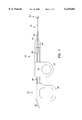
- FIG. 1 is an overall view of the optical biopsy forceps according to the present invention
- FIG. 2 is a cross-sectional view at an enlarged scale of the distal end of the forceps of FIG. 1, with the forceps jaws open;
- FIG. 3 is a view of the distal end of the forceps of FIG. 1, with the forceps jaws closed;
- FIG. 4 is a perspective view of the fiber tube assembly and related components, for the distal end of the device of FIG. 2;
- FIG. 5A is a top view, at an enlarged scale, of a component of the distal end of the device of FIG. 2;
- FIG. 5B is a side sectional view taken along the line 5B--5B of FIG. 5A;
- FIG. 5C is an end view of the component of the distal end of the device of FIG. 2;
- FIGS. 6A and 6B are top and side views, respectively, of a cutting jaw component of the distal end of the device of FIG. 2;
- FIG. 7 is an overall view of another embodiment of the optical biopsy forceps according to the present invention.
- FIG. 8 is a cross-sectional view of the distal end of an optical biopsy forceps provided in accordance with a further embodiment of the invention.
- Forceps 10 is adapted for use internally of the body, for example in connection with endoscopic, laparoscopic or vascular procedures.
- Forceps 10 includes a control handle portion 12 at the proximal end, a middle portion 14 which extends over the main length of the device, and a distal end 16 which includes opposed forceps cutting jaws and distal end of the optical fiber, as is explained in greater detail below.
- the main body or length of the forceps 10 consists of coaxial inner and an outer tubular members.
- the inner tubular member is a hollow plastic tube 20
- the outer tubular member or catheter body is coil 22.
- the coil 22 is a finely wound spiral coil of stainless steel as is generally known and used in catheters and guidewires.
- the outer tubular member could be made using another plastic tube, or a plastic/metal composite structure, in place of coil 22.
- the plastic tube 20 is positioned within coil 22 and these components are dimensioned with respect to each other so that tube 20 may be free to move axially within coil 22 during actuation of the jaws, as is explained below.
- a pair of control wires 40, 41, and the optical fiber 50 Positioned within inner tube 20 are a pair of control wires 40, 41, and the optical fiber 50. These components, together with outer coil 22 and inner plastic tube 20 extend over the main length of the device, from the distal end 16 to the handle portion 12. At the handle, coil 22 and tube 20 pass through a plastic sleeve 24, which serves as a reinforcement and strain relief, into a bore 25 in the tip 13 of the handle 12. The plastic sleeve 24 and the proximal end of the coil 22 are received and secured, as by bonding, in the tip 13 of the handle 12.
- the inner plastic tube 20, control wires 40, 41 and fiber 50 are not secured at tip 13, but pass through bore 25, through a stainless steel reinforcing tube 29 to slider 30, which is movably received in a slot 28 in handle 12.
- Reinforcing tube 29, tube 20 and control wires 40, 41 are secured to slider 30 which together form an actuator mechanism for the forceps 10. Movement of slider 30 causes axial movement of reinforcing tube 29, tube 20 and control wires 40, 41 relative to coil 22, which is used to actuate the cutting jaws.
- Loops 26 and 27 are provided in handle 12 and slider 30, to form finger holes useful in grasping and manipulating the forceps.
- Optical fiber 50 extends through slider 30, and out of handle 12, in a protective cable or sheath 32, for connection to electro-optical units (not shown) which provide the illumination light to the fiber, and which receive and analyze the returned right from the target at distal the end of the forceps.
- the optical biopsy forceps of the present invention may be used with any type of electro-optical technique for guiding the forceps. This may include systems which use viewing or imaging, systems which use illumination with white light to excite dyes in the area of interest, and spectroscopic techniques to identify tissue types by spectral analysis of light returned from tissue illuminated with light of certain wavelengths. Such spectroscopic techniques utilize the property of certain tissue types to reflect or fluoresce light having characteristic wavelengths.
- the distal end 16 of the optical forceps includes a yoke 60, which serves as a mounting member for the cutting jaws.
- Yoke 60 may be machined from stainless steel or formed of other suitable material. It generally has a proximal portion or section indicated by reference number 61, a center section 62, and a distal section 63 having inwardly curved opposing distal end portions 63a and 63b.
- Yoke 60 has a bore 64 running therethrough.
- Each of the opposing distal end portions 63a and 63b has an arc shaped groove 65 (FIGS. 5B and 5C) formed therein which defines a guide slot for the distal end of the fiber 50.
- the diameter of the bore defined by the arcuate grooves 65 can be stepped to a smaller size at distal end portions 63a and 63b.
- Sections 61 and 62 are generally circular in section. Section 61 has a diameter corresponding to the inside dimension of coil 22, while section 62 has a diameter corresponding to the outside dimension of coil 22, so that the end of coil 22 may be received and bonded to section 61.
- the proximal end surface 56 of the yoke 60 cooperates with the distal end 21 of the inner tube 20 to provide a limit stop for the fiber tube assembly 52 when it is being advanced within the outer tube 22 to open the jaws.
- Center section 62 has a pair of holes 68, 69 which receive pins 72, 73 to hold the jaws in place.
- Distal section 63 is stepped down relative to section 62, as seen in side view in FIGS. 2 and 5B, to allow the jaws 80 and 81 to fold against it when the jaws are closed (FIG. 3) so as to have a thin profile for ease of introduction and navigation.
- Distal section 63 also has a vertical slot 70 provided therein which is dimensioned to the size of the mounting ends of the lever arms 85 of the jaws.
- the inner wall 71 of distal section 63 is stepped outwardly relative to the slot 70 to provide clearance for the ends of control wires 40 and 41.
- jaw 80 and 81 are similar only one is described in detail here.
- the two jaws are mirror-image identical, but with their serrations staggered so that they will mesh.
- jaw 80 has a rearward lever or mounting portion 85, and a distal cup or sample receiving portion 82, which has sharp serrations 83 used to cut the tissue sample.
- the lever portion 85 has a hole 84 formed to receive the pin 72 which thus serves to retain the jaws, and also to acts as the pivot point.
- a hole 86 is provided at the forward apex of the relieved section, to receive the end of control wire 40 (or 41) which is crimped or bent at a right angle at its tip to be effectively captured.
- the control wires are formed of wire which is stiff enough to push against the jaws to open them, but flexible enough to flex as the wires are retracted to pull the jaws together.
- the distal end 16 of the optical forceps also includes a fiber tube assembly 52. It includes a tube 54 which may be machined from stainless steel, or formed of other suitable material. The end of plastic tube 20 overlaps end 55 of the tube 54 and is bonded to tube 54. The control wires 40, 41 and the optical fiber 50 pass into it from the plastic tube 20. The optical fiber and the control wires pass axially through the tube 54 and are bonded to the tube 54 by epoxy or other suitable adhesive.
- the optical fiber 50 includes a jacket 87 of polyamide or similar material and an outer protective tube 88 made of stainless steel, for example. The jacket 87 extends the length of the optical fiber from its proximal end to its proximal end.
- the protective tube 88 extends from the distal end of the optical fiber to at least a point located within the distal end of tube 54.
- the distal end of the optical fiber 50 is flush with the end of the protective tube 88, and may have a lens or clear epoxy coating, depending on the optical properties desired.
- the protective tube 88 at the distal end of the optical fiber is designed to give strength to prevent damage to the fiber by tweezers and the like when tissue is removed from the biopsy jaws.
- the slider 30 in operation, is retracted toward the back of handle 12 to close the jaws. This causes movement (to the left in FIG. 2) of plastic tube 20, the fiber tube assembly 52, the control wires 40, 41, and the optical fiber 50. This retracts the optical fiber into the yoke 60 and the pulling of the control wires closes the jaws.
- the distal end is of the same narrow diameter as the main body of the forceps catheter, and the closed jaws have a smooth, rounded shape to facilitate introduction and navigation in the vascular, endoscopic or laproscopic systems.
- the cutting jaws are coaxially positioned with respect to the distal end of the optical fiber.
- the forceps jaws can be opened by pushing slider 30 of the control handle forward. This causes movement (to the right in FIG. 2) of plastic tube 20, the fiber tube assembly 52, the control wires 40, 41, and the optical fiber 50.
- the control wires push against the jaws, causing them to open.
- the tip of the optical fiber is axially extended.
- the distal end or tip of the optical fiber is positioned at the distal end of the catheter body with its optical view axis or view axis aligned for a tissue analysis zone adjacent the distal tip of the catheter body and positioned at the area of contact of the cutting jaws when the cutting jaws are operated to their closed cutting position.
- the device may then be used for optical tissue identification.
- slider 30 When an area of disease is identified and a biopsy of it is needed, slider 30 is pulled, retracting the tip of the fiber and simultaneously causing the jaws to close and cut a biopsy sample at the exact place being viewed by the fiber.
- the biopsy sample is cut from the exact tissue site identified by the spectroscopic analysis step without requiring moving or repositioning of the catheter body.
- the forceps may then be withdrawn from the patient to recover the sample for analysis.
- the analysis of the withdrawn sample can be conducted using known laboratory techniques to confirm the identification of the tissue sample made by spectroscopic analysis.
- the optical biopsy forceps of the invention is used for spectroscopically analyzing tissue in the tissue analysis zone adjacent the distal end of the forceps through the use of an electro-optic tissue analysis system connected to the proximal end of the optical fiber.
- the optical biopsy forceps are guided spectroscopically within the body to an area of interest as identified by the spectroscopic analysis of tissue type in the tissue analysis zone adjacent the distal tip of the catheter body.
- FIG. 7 another embodiment of an integrated optical biopsy forceps of the present invention is generally indicated by reference number 90.
- the optical forceps 90 is generally similar to the optical forceps 10 shown in FIG. 1, and accordingly, corresponding elements have been given the same reference number.
- the optical biopsy forceps is adapted for use internally of the body, for example in connection with endoscopic, laparoscopic or vascular procedures.
- Forceps 90 includes a handle portion 91 and an operating lever 92 at the proximal end, a middle portion 14 which extends over the main length of the device, and a distal end 16.
- the distal end 16 includes forceps cutting jaws 80 and 81 and the distal end of the optical fiber 50 which is contained within a plastic tube, corresponding to plastic tube 20 of forceps 10, and pass through a sleeve 24 in the manner illustrated in FIGS. 1-6 for the forceps 10.
- the operating lever 92 has its upper end 93 pivoted to the handle 91 by a pivot pin 94.
- the forceps 90 includes a reinforcing tube, corresponding to reinforcing tube 29 of forceps 10, which encloses the fiber optical tube, and control wires 40 and 41.
- the control wires pass around a post 95 and are secured to the operating lever 92 near its upper end 93 located within the handle.
- the optical fiber tube extends out of the handle in a protective sheath 32 as described above with reference to optical biopsy forceps 10.
- Loops 97 are provided in the handle 91 and the operating lever 92, forming finger holes useful in grasping and manipulating the forceps.
- the operating lever also has curved regions 99 forming finger rests, which together with the depending operating lever arrangement of the forceps 90, enhance the ergonomics of the instrument.
- the jaws 80 and 81 are open when the relative position between the handle 91 and the operating lever 92 is as illustrated in FIG. 6.
- the control wires 40 and 41 are drawn around the post 95, retracting the optical fiber and operating the jaws 80 and 81 closed in a manner similar to that described for the operation of forceps 10.
- the control wires are advanced within tube 20, causing the jaws to open.
- the optical biopsy forceps includes an optical fiber 150 and opposed forceps cutting jaws 180 and 181, which can be similar to the optical fiber and the jaws of forceps 10 shown in FIGS. 1-6.
- the optical fiber 150 of the optical biopsy forceps includes an outer tubular, sheath-like member or catheter body 110, which corresponds to the outer sheath or coil 22 (FIG. 2), and a reinforcement cover 116, which, for example, can be a metal coil or cable, a nylon sheath, or any other suitable cover.
- the reinforced optical fiber is movable axially within the sheath 110.
- the optical biopsy forceps further includes a tubular slide member connected to the optical fiber and movable therewith, and coupled to the jaws 180 and 181 for actuating the jaws 180 and 181 as the optical fiber is moved within the outer sheath 110.
- the optical biopsy forceps includes a suitable handle (not shown) for facilitating actuation of the tubular slide member 120.
- the handle is similar to the handle 12 (FIG. 1) of the optical biopsy forceps 10, but the handle can include any type of actuating mechanism capable of imparting bidirectional axial movement to the optical fiber 150 of the optical biopsy forceps.
- the optical fiber 150 positioned within the outer sheath extends over the main length of the device, from the distal end 106 to the handle.
- the proximal end of the sheath 110 passes through a sleeve, such as sleeve 24, and is secured to the tip of the handle.
- the sleeve provides reinforcement and strain relief where the sheath 110 is attached to the handle.
- the proximal end of the optical fiber 150 also passes through sleeve 24 and is secured to the slider 30 of the handle 12 distally of the proximal end of the optical fiber 150, the end portion of which passes through the slider and out of the handle for connection to suitable electro-optical units in the manner that has been described for the optical fiber 50 of optical biopsy forceps 10.
- the slider 30 of the handle is adapted to push the reinforced optical fiber 150, which in turn pushes the tubular slide member 120, to open the jaws of the optical biopsy forceps and to pull the reinforced optical fiber, pulling the tubular slide member 120, to close the jaws.
- the optical biopsy forceps of the present invention can be used with any type of electro-optical technique for guiding the forceps.
- This may include systems which use viewing or imaging, systems which use illumination with white light to excite dyes in the area of interest, and spectroscopic techniques to identify tissue types by spectral analysis of light returned from tissue illuminated with light of certain wavelengths.
- spectroscopic techniques utilize the property of certain tissue types to reflect or fluoresce light having characteristic wavelengths.
- the sheath 110 is a flexible hollow catheter which can be made a plastic tube, or a plastic/metal composite structure that defines an opening or bore therethrough.
- the outer sheath 110 can be similar to those of disposable biopsy forceps commonly used with colonoscopes used in the upper and lower gastrointestinal tracts, and broncoscopes used in the trachea and bronchus.
- the outer sheath 110 can be a rigid tube, such as those of biopsy forceps commonly used with cystoscopes, colposcopes and laproscopes.
- the optical fiber 150 extends through a central bore 119 formed through a tubular slide member 120 which, in turn, is mounted in a mounting member or jaw support block 122 which serves as a mounting member for the cutting jaws 180, 181.
- the jaw support block 122 can be machined from stainless steel or formed of other suitable material.
- the jaw support block 122 has a bore 124 running therethrough which is generally circular in section.
- the inner dimension of the jaw support block 122 corresponds to the outer dimension of the outer sheath 110 which is secured to the support block in a suitable manner, such as with cement or by crimping.
- the jaws 180, 181 are hinged to the support block 122 which has a pair of holes which receive pins 130, 132 which pass through ears 134 of the jaws to hold the jaws 180, 181 in place.
- the attachment of the jaws to the support block by ears 134 allows the jaws 180, 181 to fold against the front end of the support block when closed so as to have a thin profile for the distal end of the forceps for ease of introduction and navigation.
- the jaw support block 122 has a slot to control travel of the jaws 180 and 181.
- the tubular slide member 120 is mounted in the bore 124 in the jaw support block 122 and is free to move axially within support block 122 during actuation of the jaws.
- the fiber 150 is secured to the tubular slide member 120 in a suitable manner such as with cement.
- the jaws 180, 181 are connected to the tubular slide member 120 by a pair of control links 136, 138, which are rigid members that function as a linkage mechanism connecting the cutting jaws to the tubular slide member.
- Control link 136 has one end 139 connected to tubular slide member 120 by a pin 140.
- the other end 141 of the control link 136 is connected to jaw 180 by a pin 142.
- control link 138 has one end 144 connected to tubular slide member 120 by a pin 146 and its other end 148 connected to jaw 181 by a pin 149.
- axial movement of the optical fiber in the direction of arrow 154 causes axial movement of tubular slide member 120, pivoting the control links 136, 138, about their ends 139 and 144, respectively, drawing the jaws together to actuate the cutting jaws 180, 181.
- the rearward surface 151 at the distal end 152 of the tubular slide member 120 is adapted to engage the forward surface 153 of the jaw support block 122, functioning as a travel limit stop surface to limit the axial movement of the tubular slide member 120 during retraction of the optical fiber 150.
- both the proximal and distal ends of the tubular slide member 120 include limit stops which prevent both over distention and over retraction of the optical fiber 150.
- the optical fiber 150 is fully retracted (by retracting the slider 30 toward the back of the handle) to move the tubular slide member 120 in the direction of the arrow 154 until its rearward surface 151 engages forward surface 152 of the jaw support block 122.
- the control links 136 and 138 have been drawn rearwardly, drawing the jaws 180, 181 together so that the jaws are closed.
- the distal end 106 of the forceps is substantially of the same narrow diameter as the outer sheath 116 which defines the main body portion of the optical biopsy forceps, and the closed jaws have a smooth, rounded shape to facilitate introduction and navigation through the biopsy channel of an endoscope, for example.
- the endoscopist advances the optical biopsy forceps through the biopsy channel of the endoscope to the general area of interest, i.e., such as a tissue site or tissue analysis zone with a body, represented by the reference numeral 170.
- the forceps jaws can be opened by advancing the slider 30, thereby advancing the optical fiber 150 forwardly through the handle. This causes the tubular slide member 120 to move forwardly (to the right in FIG. 8), which in turn causes pivoting of the control links 136 and 138. As the control links pivot, the control links push against the jaws, causing the jaws to open. Simultaneously, the distal tip of the optical fiber 150 is axially extended forwardly beyond the jaws. The forceps may then be used for optical tissue identification.
- the slider 30 When an area of disease is identified and if a biopsy of it is needed, the slider 30 is retracted, retracting the optical fiber 150 and thus the tubular slide member 120, retracting the tip of the optical fiber and simultaneously causing the jaws to close and cut a biopsy sample at the exact place that has been located by viewing through the optical fiber.
- the endoscopist holding the instrument by the handle gently pulls back on the slider of the handle, retracting the optical fiber and tubular slide member 120, moving the optical fiber away from the tissue surface.
- the jaws begin to close as the tubular slide member is moved in the direction of the arrow 154.
- the endoscopist gently pushes on the instrument to urge the jaws towards the tissue surface so that a tissue sample will be captured by the jaws as they close.
- the endoscopist pulls the entire assembly away from the tissue surface and then withdraws the optical biopsy forceps from the endoscope so that the specimen tissue can be retrieved.
- the present invention has provided an optical biopsy forceps.
- An important feature of the invention is that the tip of the optical fiber 50 (and optical fiber 150) is coaxial with, and perfectly aligned with, the zone where the two jaws 80, 81 (and jaws 180, 181) intersect and the sample is taken.
- This, together with the slim and compact profile of the device when the jaws are retracted, is a great improvement over prior art devices.
- the fiber optic assembly including the optical fiber and the tubular slide member of the biopsy forceps, can be produced as a disposable assembly, with the rest of the biopsy forceps being produced as a non-disposable unit.
- the major advantage of forceps 100 as compared to forceps 10 is, because the biopsy jaw control wires 40, 41 are not required, larger diameter optical fibers can be used to increase the detected signal relative to noise.
Abstract
Description
Claims (6)
Priority Applications (1)
| Application Number | Priority Date | Filing Date | Title |
|---|---|---|---|
| US08/975,734 US6129683A (en) | 1996-05-07 | 1997-11-21 | Optical biopsy forceps |
Applications Claiming Priority (2)
| Application Number | Priority Date | Filing Date | Title |
|---|---|---|---|
| US08/644,080 US5762613A (en) | 1996-05-07 | 1996-05-07 | Optical biopsy forceps |
| US08/975,734 US6129683A (en) | 1996-05-07 | 1997-11-21 | Optical biopsy forceps |
Related Parent Applications (1)
| Application Number | Title | Priority Date | Filing Date |
|---|---|---|---|
| US08/644,080 Continuation US5762613A (en) | 1996-05-07 | 1996-05-07 | Optical biopsy forceps |
Publications (1)
| Publication Number | Publication Date |
|---|---|
| US6129683A true US6129683A (en) | 2000-10-10 |
Family
ID=24583369
Family Applications (2)
| Application Number | Title | Priority Date | Filing Date |
|---|---|---|---|
| US08/644,080 Expired - Lifetime US5762613A (en) | 1996-05-07 | 1996-05-07 | Optical biopsy forceps |
| US08/975,734 Expired - Lifetime US6129683A (en) | 1996-05-07 | 1997-11-21 | Optical biopsy forceps |
Family Applications Before (1)
| Application Number | Title | Priority Date | Filing Date |
|---|---|---|---|
| US08/644,080 Expired - Lifetime US5762613A (en) | 1996-05-07 | 1996-05-07 | Optical biopsy forceps |
Country Status (7)
| Country | Link |
|---|---|
| US (2) | US5762613A (en) |
| EP (1) | EP0910284B1 (en) |
| JP (1) | JP3220164B2 (en) |
| AT (1) | ATE352256T1 (en) |
| CA (1) | CA2253643C (en) |
| DE (1) | DE69737289T2 (en) |
| WO (1) | WO1997041776A1 (en) |
Cited By (79)
| Publication number | Priority date | Publication date | Assignee | Title |
|---|---|---|---|---|
| US6308092B1 (en) * | 1999-10-13 | 2001-10-23 | C. R. Bard Inc. | Optical fiber tissue localization device |
| US6368327B2 (en) * | 1997-04-29 | 2002-04-09 | Raymond F. Lippitt | Medical device |
| US20020068946A1 (en) * | 2000-12-06 | 2002-06-06 | Kortenbach Juergen A. | Apparatus for the endoluminal treatment of gastroesophageal reflux disease (GERD) |
| US20020068945A1 (en) * | 2000-12-06 | 2002-06-06 | Robert Sixto | Surgical clips particularly useful in the endoluminal treatment of gastroesophageal reflux disease (GERD) |
| US20020078967A1 (en) * | 2000-12-06 | 2002-06-27 | Robert Sixto | Methods for the endoluminal treatment of gastroesophageal reflux disease (GERD) |
| US6416519B1 (en) * | 1999-11-15 | 2002-07-09 | Vandusseldorp Gregg A. | Surgical extraction device |
| US20020173799A1 (en) * | 2000-12-06 | 2002-11-21 | Intumed Ltd. | Apparatus for self-guided intubation |
| WO2003059150A2 (en) | 2002-01-09 | 2003-07-24 | Neoguide Systems, Inc. | Apparatus and method for spectroscopic examination of the colon |
| US20030191464A1 (en) * | 2002-04-09 | 2003-10-09 | Pentax Corporation | Endoscopic forceps instrument |
| US20030225432A1 (en) * | 2002-05-31 | 2003-12-04 | Baptiste Reginald C. | Soft tissue retraction device for an endoscopic instrument |
| WO2004045398A1 (en) * | 2002-11-20 | 2004-06-03 | Aesculap Ag & Co. Kg | Endoscope |
| US20040186348A1 (en) * | 2003-03-18 | 2004-09-23 | Pentax Corporation | Pincerlike instrument for electronic endoscope |
| US20050010235A1 (en) * | 2003-07-09 | 2005-01-13 | Vandusseldorp Gregg A. | Surgical device |
| US20050049520A1 (en) * | 2003-09-03 | 2005-03-03 | Nakao Naomi L. | Needle biopsy forceps with integral sample ejector |
| US20050125010A1 (en) * | 2001-06-25 | 2005-06-09 | Smith Kevin W. | Flexible surgical clip applier |
| US20060178699A1 (en) * | 2005-01-20 | 2006-08-10 | Wilson-Cook Medical Inc. | Biopsy forceps |
| US7118586B1 (en) | 1999-10-25 | 2006-10-10 | Boston Scientific Scimed, Inc. | Forceps for medical use |
| US20070021749A1 (en) * | 2005-06-21 | 2007-01-25 | Keita Suzuki | High-frequency treatment instrument |
| US20070093703A1 (en) * | 2005-10-24 | 2007-04-26 | Sievert Chester E Jr | System and method for non-endoscopic optical biopsy detection of diseased tissue |
| US20070142851A1 (en) * | 2000-12-06 | 2007-06-21 | Ethicon Endo-Surgery, Inc. | Methods for the endoluminal treatment of gastroesophageal reflux disease (GERD) |
| US20070299468A1 (en) * | 2006-06-22 | 2007-12-27 | Viola Frank J | Tissue vitality comparator with light pipe with fiber optic imaging bundle |
| US20080045859A1 (en) * | 2006-08-19 | 2008-02-21 | Fritsch Michael H | Devices and Methods for In-Vivo Pathology Diagnosis |
| US20080097519A1 (en) * | 2006-10-20 | 2008-04-24 | Alfred E. Mann Foundation For Scientific Research | Medical device extraction tool |
| US20080188873A1 (en) * | 2005-01-21 | 2008-08-07 | Giovanni Speziali | Thorascopic Heart Valve Repair Method and Apparatus |
| US20080194910A1 (en) * | 2007-02-08 | 2008-08-14 | Olympus Medical Systems Corp. | Treatment tool for endoscope |
| US20080195143A1 (en) * | 2007-02-08 | 2008-08-14 | Olympus Medical Systems Corp. | Endoscope treatment tool |
| WO2009111717A1 (en) * | 2008-03-06 | 2009-09-11 | Trustees Of Boston University | Low cost disposable medical forceps to enable a hollow central channel for various functionalities |
| US20090259248A1 (en) * | 2006-06-14 | 2009-10-15 | Hans Ganter | Surgical gripping forceps |
| US20100168610A1 (en) * | 2008-12-31 | 2010-07-01 | Mauna Kea Technologies | Multi-purpose biopsy forceps |
| US7762960B2 (en) | 2005-05-13 | 2010-07-27 | Boston Scientific Scimed, Inc. | Biopsy forceps assemblies |
| US20100198106A1 (en) * | 2007-02-19 | 2010-08-05 | Multi Biopsy Sampling Co. Aps | Biopsy forceps for taking one or more samples |
| US20100268025A1 (en) * | 2007-11-09 | 2010-10-21 | Amir Belson | Apparatus and methods for capsule endoscopy of the esophagus |
| US7828811B2 (en) | 2000-12-06 | 2010-11-09 | Ethicon Endo-Surgery, Inc. | Surgical clip application assembly |
| US7857827B2 (en) | 2006-04-14 | 2010-12-28 | Ethicon Endo-Surgery, Inc. | Endoscopic device |
| US20110060189A1 (en) * | 2004-06-30 | 2011-03-10 | Given Imaging Ltd. | Apparatus and Methods for Capsule Endoscopy of the Esophagus |
| US20110071554A1 (en) * | 2000-12-06 | 2011-03-24 | Mcbrayer Michael Sean | Surgical Clips Particularly Useful in the Endoluminal Treatment of Gastroesophageal Reflux Disease (GERD) |
| US7942896B2 (en) | 2003-11-25 | 2011-05-17 | Scimed Life Systems, Inc. | Forceps and collection assembly and related methods of use and manufacture |
| US7998167B2 (en) | 2006-04-14 | 2011-08-16 | Ethicon Endo-Surgery, Inc. | End effector and method of manufacture |
| US20110224705A1 (en) * | 2010-03-12 | 2011-09-15 | Ueno Tomio | Surgical tool for anastomosis |
| US20110230910A1 (en) * | 2010-03-18 | 2011-09-22 | Joshua Benjamin Stopek | Surgical grasper with integrated probe |
| US20110270255A1 (en) * | 2010-04-30 | 2011-11-03 | Graham Smith | Guide For Drilling An Irregular-Shaped Body |
| US8062212B2 (en) | 2000-04-03 | 2011-11-22 | Intuitive Surgical Operations, Inc. | Steerable endoscope and improved method of insertion |
| US8083686B2 (en) | 2003-09-10 | 2011-12-27 | Boston Scientific Scimed, Inc. | Forceps and collection assembly with accompanying mechanisms and related methods of use |
| US8083879B2 (en) | 2005-11-23 | 2011-12-27 | Intuitive Surgical Operations, Inc. | Non-metallic, multi-strand control cable for steerable instruments |
| US8182418B2 (en) | 2008-02-25 | 2012-05-22 | Intuitive Surgical Operations, Inc. | Systems and methods for articulating an elongate body |
| US8313500B2 (en) | 2006-04-14 | 2012-11-20 | Ethicon Endo-Surgery, Inc. | Endoscopic device |
| US8361090B2 (en) | 2002-01-09 | 2013-01-29 | Intuitive Surgical Operations, Inc. | Apparatus and method for endoscopic colectomy |
| US8469993B2 (en) | 2003-06-18 | 2013-06-25 | Boston Scientific Scimed, Inc. | Endoscopic instruments |
| US8517923B2 (en) | 2000-04-03 | 2013-08-27 | Intuitive Surgical Operations, Inc. | Apparatus and methods for facilitating treatment of tissue via improved delivery of energy based and non-energy based modalities |
| US8568299B2 (en) | 2006-05-19 | 2013-10-29 | Intuitive Surgical Operations, Inc. | Methods and apparatus for displaying three-dimensional orientation of a steerable distal tip of an endoscope |
| US8721530B2 (en) | 2000-04-03 | 2014-05-13 | Intuitive Surgical Operations, Inc. | Tendon-driven endoscope and methods of use |
| US8845524B2 (en) | 2000-04-03 | 2014-09-30 | Intuitive Surgical Operations, Inc. | Steerable segmented endoscope and method of insertion |
| US8882657B2 (en) | 2003-03-07 | 2014-11-11 | Intuitive Surgical Operations, Inc. | Instrument having radio frequency identification systems and methods for use |
| US8888688B2 (en) | 2000-04-03 | 2014-11-18 | Intuitive Surgical Operations, Inc. | Connector device for a controllable instrument |
| US8888813B2 (en) | 2008-10-20 | 2014-11-18 | Spine View, Inc. | Retractor cannula system for accessing and visualizing spine and related methods |
| US9044221B2 (en) | 2010-12-29 | 2015-06-02 | Neochord, Inc. | Exchangeable system for minimally invasive beating heart repair of heart valve leaflets |
| US9192374B2 (en) | 2007-10-18 | 2015-11-24 | Neochord, Inc. | Minimally invasive repair of a valve leaflet in a beating heart |
| US9220398B2 (en) | 2007-10-11 | 2015-12-29 | Intuitive Surgical Operations, Inc. | System for managing Bowden cables in articulating instruments |
| USD758581S1 (en) | 2015-03-26 | 2016-06-07 | United States Endoscopy Group, Inc. | Grasper |
| US20160361051A1 (en) * | 2015-06-09 | 2016-12-15 | Boston Scientific Scimed, Inc. | System for the parallel delivery of an element into the esophageal mucosa |
| USD779668S1 (en) | 2015-03-26 | 2017-02-21 | United States Endoscopy Group, Inc. | Grasper |
| US9681857B2 (en) | 2003-06-18 | 2017-06-20 | Boston Scientific Scimed, Inc. | Endoscopic instruments and methods of manufacture |
| US9826992B2 (en) | 2007-12-21 | 2017-11-28 | Smith & Nephew, Inc. | Multiple portal guide |
| US9888936B2 (en) | 2010-09-27 | 2018-02-13 | Smith & Nephew, Inc. | Device and methods for use during arthroscopic surgery |
| US9913636B2 (en) | 2007-12-21 | 2018-03-13 | Smith & Nephew, Inc. | Multiple portal guide |
| US10219812B2 (en) | 2010-11-03 | 2019-03-05 | Smith & Nephew, Inc. | Drill guide |
| WO2019094948A1 (en) | 2017-11-13 | 2019-05-16 | UVision360, Inc. | Biopsy device and method |
| US10512392B2 (en) | 2008-02-06 | 2019-12-24 | Intuitive Surgical Operations, Inc. | Segmented instrument having braking capabilities |
| US10588620B2 (en) | 2018-03-23 | 2020-03-17 | Neochord, Inc. | Device for suture attachment for minimally invasive heart valve repair |
| US10695178B2 (en) | 2011-06-01 | 2020-06-30 | Neochord, Inc. | Minimally invasive repair of heart valve leaflets |
| US10765517B2 (en) | 2015-10-01 | 2020-09-08 | Neochord, Inc. | Ringless web for repair of heart valves |
| US10966709B2 (en) | 2018-09-07 | 2021-04-06 | Neochord, Inc. | Device for suture attachment for minimally invasive heart valve repair |
| US11096563B2 (en) | 2005-11-22 | 2021-08-24 | Intuitive Surgical Operations, Inc. | Method of determining the shape of a bendable instrument |
| US11173030B2 (en) | 2018-05-09 | 2021-11-16 | Neochord, Inc. | Suture length adjustment for minimally invasive heart valve repair |
| US11253360B2 (en) | 2018-05-09 | 2022-02-22 | Neochord, Inc. | Low profile tissue anchor for minimally invasive heart valve repair |
| US11337715B2 (en) | 2015-03-26 | 2022-05-24 | United States Endoscopy Group, Inc. | Endoscopic grasping device |
| US11376126B2 (en) | 2019-04-16 | 2022-07-05 | Neochord, Inc. | Transverse helical cardiac anchor for minimally invasive heart valve repair |
| US11589989B2 (en) | 2017-03-31 | 2023-02-28 | Neochord, Inc. | Minimally invasive heart valve repair in a beating heart |
| US11957584B2 (en) | 2021-11-11 | 2024-04-16 | Neochord, Inc. | Suture length adjustment for minimally invasive heart valve repair |
Families Citing this family (62)
| Publication number | Priority date | Publication date | Assignee | Title |
|---|---|---|---|---|
| US6564087B1 (en) | 1991-04-29 | 2003-05-13 | Massachusetts Institute Of Technology | Fiber optic needle probes for optical coherence tomography imaging |
| US6485413B1 (en) | 1991-04-29 | 2002-11-26 | The General Hospital Corporation | Methods and apparatus for forward-directed optical scanning instruments |
| US6111645A (en) | 1991-04-29 | 2000-08-29 | Massachusetts Institute Of Technology | Grating based phase control optical delay line |
| US5762613A (en) * | 1996-05-07 | 1998-06-09 | Spectrascience, Inc. | Optical biopsy forceps |
| US6296608B1 (en) * | 1996-07-08 | 2001-10-02 | Boston Scientific Corporation | Diagnosing and performing interventional procedures on tissue in vivo |
| US6508825B1 (en) | 1997-02-28 | 2003-01-21 | Lumend, Inc. | Apparatus for treating vascular occlusions |
| US6217549B1 (en) | 1997-02-28 | 2001-04-17 | Lumend, Inc. | Methods and apparatus for treating vascular occlusions |
| WO1998040015A2 (en) * | 1997-03-13 | 1998-09-17 | Biomax Technologies, Inc. | Catheters and endoscopes comprising optical probes and bioptomes and methods of using the same |
| US6201989B1 (en) | 1997-03-13 | 2001-03-13 | Biomax Technologies Inc. | Methods and apparatus for detecting the rejection of transplanted tissue |
| US6484050B1 (en) * | 1997-11-18 | 2002-11-19 | Care Wise Medical Products Corporation | Minimally invasive surgical instrument for tissue identification, dislodgment and retrieval and methods of use |
| US5961458A (en) * | 1997-11-18 | 1999-10-05 | Carewise Medical Products Corporation | Minimally invasive surgical probe for tissue identification and retrieval and method of use |
| US6066102A (en) * | 1998-03-09 | 2000-05-23 | Spectrascience, Inc. | Optical biopsy forceps system and method of diagnosing tissue |
| US6174291B1 (en) | 1998-03-09 | 2001-01-16 | Spectrascience, Inc. | Optical biopsy system and methods for tissue diagnosis |
| US6299860B1 (en) * | 1998-10-15 | 2001-10-09 | Fluoro Probe, Inc. | Method for viewing diseased tissue located within a body cavity |
| US6652836B2 (en) | 1998-10-15 | 2003-11-25 | Fluoroprobe, Inc. | Method for viewing tumor tissue located within a body cavity |
| US6284223B1 (en) * | 1998-10-15 | 2001-09-04 | Fluoroprobe, Inc. | Method for viewing tumor tissue located within a body cavity |
| US6248124B1 (en) * | 1999-02-22 | 2001-06-19 | Tyco Healthcare Group | Arterial hole closure apparatus |
| US6445939B1 (en) | 1999-08-09 | 2002-09-03 | Lightlab Imaging, Llc | Ultra-small optical probes, imaging optics, and methods for using same |
| JP3655785B2 (en) * | 1999-10-18 | 2005-06-02 | ペンタックス株式会社 | Endoscopic treatment tool |
| US7555333B2 (en) | 2000-06-19 | 2009-06-30 | University Of Washington | Integrated optical scanning image acquisition and display |
| US20020058961A1 (en) * | 2000-10-16 | 2002-05-16 | Aguilar Amiel R. | Catheter |
| US20020143358A1 (en) * | 2001-02-13 | 2002-10-03 | Domingo Nicanor A. | Method and apparatus for micro-dissection of vascular occlusions |
| JP4295925B2 (en) * | 2001-03-01 | 2009-07-15 | Hoya株式会社 | Bipolar high-frequency treatment instrument for endoscope |
| JP5073895B2 (en) | 2001-09-25 | 2012-11-14 | オリンパス株式会社 | Endoscopic treatment tool |
| JP4420593B2 (en) * | 2002-07-29 | 2010-02-24 | Hoya株式会社 | Bipolar high-frequency treatment instrument for endoscope |
| DE10258483B3 (en) * | 2002-12-10 | 2004-06-17 | Universitätsklinikum Charité, Medizinische Fakultät der Humboldt-Universität zu Berlin | Optical biopsy instrument for extracting breast tissue sample from milk duct having endoscope displaced within cylindrical channel having side opening with cutting edge |
| JP4653104B2 (en) * | 2003-06-10 | 2011-03-16 | ルーメンド インコーポレイテッド | Catheter apparatus and method for opening a vascular occlusion |
| EP2455016B1 (en) * | 2003-09-09 | 2014-06-18 | Olympus Corporation | Treatment tool for endoscope |
| JP4593096B2 (en) * | 2003-09-09 | 2010-12-08 | オリンパス株式会社 | Endoscopic treatment tool |
| US7901348B2 (en) | 2003-12-12 | 2011-03-08 | University Of Washington | Catheterscope 3D guidance and interface system |
| ES2409160T3 (en) * | 2004-03-23 | 2013-06-25 | Boston Scientific Limited | Live View System |
| US7530948B2 (en) | 2005-02-28 | 2009-05-12 | University Of Washington | Tethered capsule endoscope for Barrett's Esophagus screening |
| EP1885259B1 (en) * | 2005-05-11 | 2016-08-17 | Mayo Foundation For Medical Education And Research | Apparatus for internal surgical procedures |
| US7658708B2 (en) * | 2005-09-20 | 2010-02-09 | Ai Medical Devices, Inc. | Endotracheal intubation device |
| WO2007067163A1 (en) | 2005-11-23 | 2007-06-14 | University Of Washington | Scanning beam with variable sequential framing using interrupted scanning resonance |
| JP2009528128A (en) | 2006-03-03 | 2009-08-06 | ユニヴァーシティ オブ ワシントン | Multi-clad optical fiber scanner |
| EP2040612A2 (en) * | 2006-07-18 | 2009-04-01 | Trustees of Boston University | Device with integrated multi-fiber optical probe and methods of use |
| US8840566B2 (en) | 2007-04-02 | 2014-09-23 | University Of Washington | Catheter with imaging capability acts as guidewire for cannula tools |
| EP1985329B1 (en) * | 2007-04-25 | 2010-06-02 | Olympus Medical Systems Corp. | Tubular member and endoscopic instrument |
| US7952718B2 (en) | 2007-05-03 | 2011-05-31 | University Of Washington | High resolution optical coherence tomography based imaging for intraluminal and interstitial use implemented with a reduced form factor |
| EP2197340A4 (en) * | 2007-09-19 | 2015-10-21 | Oncofluor Inc | Method for imaging and treating organs and tissues |
| WO2009082477A2 (en) * | 2007-12-18 | 2009-07-02 | Bovie Medical | Surgical apparatus with removable tool cartridge |
| US20100198191A1 (en) | 2007-12-20 | 2010-08-05 | Acclarent, Inc. | Method and system for treating target tissue within the eustachian tube |
| US8221418B2 (en) | 2008-02-07 | 2012-07-17 | Tyco Healthcare Group Lp | Endoscopic instrument for tissue identification |
| WO2009150563A2 (en) * | 2008-06-12 | 2009-12-17 | Koninklijke Philips Electronics N.V. | Biopsy device with acoustic element |
| US20140200577A1 (en) * | 2011-05-04 | 2014-07-17 | George Klein | Ablation grasper |
| CN102232852A (en) * | 2011-05-06 | 2011-11-09 | 潘文胜 | Biopsy forceps using optical fiber for focusing |
| CN102379727A (en) * | 2011-09-02 | 2012-03-21 | 王宝根 | Multifunctional biopsy forceps |
| WO2013056190A1 (en) * | 2011-10-15 | 2013-04-18 | Transmed7, Llc | Soft tissue coring biopsy devices and methods |
| DE102012109387A1 (en) * | 2012-10-02 | 2014-04-03 | Aesculap Ag | Surgical instrument and in particular electrosurgical instrument |
| US9592079B1 (en) * | 2013-03-14 | 2017-03-14 | Matt D. Pursley | Device and method for assisting removal of items endovascularly |
| EP3185783B1 (en) | 2014-08-28 | 2019-11-13 | Koninklijke Philips N.V. | Side-looking lung biopsy device |
| CZ2014691A3 (en) * | 2014-10-10 | 2016-01-06 | Oprox, A.S. | Catheter for optical biopsy |
| US20160256140A1 (en) * | 2015-03-03 | 2016-09-08 | United States Endoscopy Group, Inc. | Microforceps |
| US9883854B2 (en) | 2015-04-08 | 2018-02-06 | Synaptive Medical (Barbados) Inc. | Systems, devices and methods for tissue removal and analysis |
| US20160367311A1 (en) * | 2015-06-16 | 2016-12-22 | Lawrence J. Gerrans | Instrumentation with Embedded Imaging Systems |
| DK178989B1 (en) * | 2015-12-30 | 2017-07-31 | 3Dintegrated Aps | A surgical instrument assembly |
| WO2017176240A1 (en) | 2016-04-04 | 2017-10-12 | Gyrus Acmi, Inc., D.B.A. Olympus Surgical Technologies Amercia | An electrosurgical illuminating instrument |
| WO2017189442A1 (en) | 2016-04-25 | 2017-11-02 | Claria Medical, Inc. | Systems and methods for tissue capture and removal |
| WO2019083896A1 (en) * | 2017-10-23 | 2019-05-02 | Claria Medical, Inc. | Systems and methods for tissue capture and removal |
| US11896285B2 (en) | 2018-03-14 | 2024-02-13 | Gyrus Acmi, Inc. | Device with movable buttons or switches and visual indicator |
| US11361918B2 (en) | 2019-03-25 | 2022-06-14 | Gyrus Acmi, Inc. | Device with movable buttons or switches and tactile identifier |
Citations (37)
| Publication number | Priority date | Publication date | Assignee | Title |
|---|---|---|---|---|
| US3074408A (en) * | 1961-05-22 | 1963-01-22 | Martin H Chester | Ureteral stone extractor and dilator |
| US3924608A (en) * | 1973-05-23 | 1975-12-09 | Olympus Optical Co | Endoscope |
| US3961621A (en) * | 1974-02-06 | 1976-06-08 | Akademiet For De Tekniske Videnskaber, Svejsecentralen | Surgical tool for taking biological samples |
| US4027510A (en) * | 1974-05-15 | 1977-06-07 | Siegfried Hiltebrandt | Forceps |
| WO1983003189A1 (en) * | 1982-03-16 | 1983-09-29 | Laserscope Inc | Surgical device for internal operations |
| US4421106A (en) * | 1976-03-19 | 1983-12-20 | Takami Uehara | Fiber scope for biopsy operable by a single operator |
| US4557255A (en) * | 1983-08-22 | 1985-12-10 | Goodman Tobias M | Ureteroscope |
| US4573450A (en) * | 1983-11-11 | 1986-03-04 | Fuji Photo Optical Co., Ltd. | Endoscope |
| US4620547A (en) * | 1983-12-31 | 1986-11-04 | Richard Wolf Gmbh | Instrument for sampling tissue specimens |
| US4646751A (en) * | 1984-05-18 | 1987-03-03 | Diener Verwaltungs-und Beteiligungsgesellschaft m.b.H. | Biopsy forceps |
| US4656999A (en) * | 1984-01-30 | 1987-04-14 | Karl Storz | Contact endoscope |
| EP0316816A1 (en) * | 1987-11-13 | 1989-05-24 | Hannes Dr. Haberl | Surgical forceps |
| EP0321132A2 (en) * | 1987-12-14 | 1989-06-21 | BAXTER INTERNATIONAL INC. (a Delaware corporation) | Optical valvulotome |
| US4887612A (en) * | 1988-04-27 | 1989-12-19 | Esco Precision, Inc. | Endoscopic biopsy forceps |
| DE3920706A1 (en) * | 1989-06-24 | 1991-01-10 | Foerster Ernst | Catheter for carrying out a biopsy - has mini-endoscope and a forceps combined with an inner sheath which slides in an outer sheath |
| WO1991001776A1 (en) * | 1989-07-31 | 1991-02-21 | Laguna Tectrix, Inc. | User energy transmission for exercise apparatus |
| US5228451A (en) * | 1990-05-10 | 1993-07-20 | Symbiosis Corporation | Biopsy forceps device having stiff distal end |
| US5280788A (en) * | 1991-02-26 | 1994-01-25 | Massachusetts Institute Of Technology | Devices and methods for optical diagnosis of tissue |
| US5291010A (en) * | 1990-10-04 | 1994-03-01 | Olympus Optical Co., Ltd. | Solid state imaging device having a chambered imaging chip corner |
| EP0593929A1 (en) * | 1992-09-23 | 1994-04-27 | United States Surgical Corporation | Surgical biopsy forceps apparatus |
| US5318023A (en) * | 1991-04-03 | 1994-06-07 | Cedars-Sinai Medical Center | Apparatus and method of use for a photosensitizer enhanced fluorescence based biopsy needle |
| WO1994012095A2 (en) * | 1992-11-18 | 1994-06-09 | Spectrascience, Inc. | Apparatus for diagnostic imaging |
| US5354291A (en) * | 1992-10-09 | 1994-10-11 | Symbiosis Corporation | Probe for endoscopic suction-irrigation instruments having a proximal port for receiving an additional probe therethrough |
| US5373854A (en) * | 1993-07-15 | 1994-12-20 | Kolozsi; William Z. | Biopsy apparatus for use in endoscopy |
| US5471992A (en) * | 1994-02-08 | 1995-12-05 | Boston Scientific Corporation | Multi-motion cutter multiple biopsy sampling device |
| US5482054A (en) * | 1990-05-10 | 1996-01-09 | Symbiosis Corporation | Edoscopic biopsy forceps devices with selective bipolar cautery |
| US5536248A (en) * | 1992-05-11 | 1996-07-16 | Arrow Precision Products, Inc. | Method and apparatus for electrosurgically obtaining access to the biliary tree and placing a stent therein |
| US5558100A (en) * | 1994-12-19 | 1996-09-24 | Ballard Medical Products | Biopsy forceps for obtaining tissue specimen and optionally for coagulation |
| US5562102A (en) * | 1994-11-21 | 1996-10-08 | Taylor; Thomas V. | Multiple biopsy device |
| US5571129A (en) * | 1995-05-15 | 1996-11-05 | Portlyn Corporation | Surgical cutting instrument with improved cleaning capability and ease of use |
| DE19533856A1 (en) * | 1995-09-13 | 1997-03-20 | Balazs Mattias | Instrument for carrying out operations by minimal invasive techniques |
| US5667473A (en) * | 1994-03-18 | 1997-09-16 | Clarus Medical Systems, Inc. | Surgical instrument and method for use with a viewing system |
| US5762613A (en) * | 1996-05-07 | 1998-06-09 | Spectrascience, Inc. | Optical biopsy forceps |
| US5843000A (en) * | 1996-05-07 | 1998-12-01 | The General Hospital Corporation | Optical biopsy forceps and method of diagnosing tissue |
| US5848978A (en) * | 1995-11-14 | 1998-12-15 | Genx International, Inc. | Surgical biopsy device |
| US5857961A (en) * | 1995-06-07 | 1999-01-12 | Clarus Medical Systems, Inc. | Surgical instrument for use with a viewing system |
| US5908381A (en) * | 1997-04-30 | 1999-06-01 | C. R. Bard Inc. | Directional surgical device for use with endoscope, gastroscope, colonoscope or the like |
-
1996
- 1996-05-07 US US08/644,080 patent/US5762613A/en not_active Expired - Lifetime
-
1997
- 1997-05-07 CA CA002253643A patent/CA2253643C/en not_active Expired - Fee Related
- 1997-05-07 WO PCT/US1997/007624 patent/WO1997041776A1/en active IP Right Grant
- 1997-05-07 DE DE69737289T patent/DE69737289T2/en not_active Expired - Lifetime
- 1997-05-07 AT AT97922685T patent/ATE352256T1/en not_active IP Right Cessation
- 1997-05-07 JP JP54014297A patent/JP3220164B2/en not_active Expired - Fee Related
- 1997-05-07 EP EP97922685A patent/EP0910284B1/en not_active Expired - Lifetime
- 1997-11-21 US US08/975,734 patent/US6129683A/en not_active Expired - Lifetime
Patent Citations (38)
| Publication number | Priority date | Publication date | Assignee | Title |
|---|---|---|---|---|
| US3074408A (en) * | 1961-05-22 | 1963-01-22 | Martin H Chester | Ureteral stone extractor and dilator |
| US3924608A (en) * | 1973-05-23 | 1975-12-09 | Olympus Optical Co | Endoscope |
| US3961621A (en) * | 1974-02-06 | 1976-06-08 | Akademiet For De Tekniske Videnskaber, Svejsecentralen | Surgical tool for taking biological samples |
| US4027510A (en) * | 1974-05-15 | 1977-06-07 | Siegfried Hiltebrandt | Forceps |
| US4421106A (en) * | 1976-03-19 | 1983-12-20 | Takami Uehara | Fiber scope for biopsy operable by a single operator |
| WO1983003189A1 (en) * | 1982-03-16 | 1983-09-29 | Laserscope Inc | Surgical device for internal operations |
| US4557255A (en) * | 1983-08-22 | 1985-12-10 | Goodman Tobias M | Ureteroscope |
| US4573450A (en) * | 1983-11-11 | 1986-03-04 | Fuji Photo Optical Co., Ltd. | Endoscope |
| US4620547A (en) * | 1983-12-31 | 1986-11-04 | Richard Wolf Gmbh | Instrument for sampling tissue specimens |
| US4656999A (en) * | 1984-01-30 | 1987-04-14 | Karl Storz | Contact endoscope |
| US4646751A (en) * | 1984-05-18 | 1987-03-03 | Diener Verwaltungs-und Beteiligungsgesellschaft m.b.H. | Biopsy forceps |
| EP0316816A1 (en) * | 1987-11-13 | 1989-05-24 | Hannes Dr. Haberl | Surgical forceps |
| EP0321132A2 (en) * | 1987-12-14 | 1989-06-21 | BAXTER INTERNATIONAL INC. (a Delaware corporation) | Optical valvulotome |
| US4887612A (en) * | 1988-04-27 | 1989-12-19 | Esco Precision, Inc. | Endoscopic biopsy forceps |
| DE3920706A1 (en) * | 1989-06-24 | 1991-01-10 | Foerster Ernst | Catheter for carrying out a biopsy - has mini-endoscope and a forceps combined with an inner sheath which slides in an outer sheath |
| WO1991001776A1 (en) * | 1989-07-31 | 1991-02-21 | Laguna Tectrix, Inc. | User energy transmission for exercise apparatus |
| US5228451A (en) * | 1990-05-10 | 1993-07-20 | Symbiosis Corporation | Biopsy forceps device having stiff distal end |
| US5482054A (en) * | 1990-05-10 | 1996-01-09 | Symbiosis Corporation | Edoscopic biopsy forceps devices with selective bipolar cautery |
| US5291010A (en) * | 1990-10-04 | 1994-03-01 | Olympus Optical Co., Ltd. | Solid state imaging device having a chambered imaging chip corner |
| US5280788A (en) * | 1991-02-26 | 1994-01-25 | Massachusetts Institute Of Technology | Devices and methods for optical diagnosis of tissue |
| US5318023A (en) * | 1991-04-03 | 1994-06-07 | Cedars-Sinai Medical Center | Apparatus and method of use for a photosensitizer enhanced fluorescence based biopsy needle |
| US5536248A (en) * | 1992-05-11 | 1996-07-16 | Arrow Precision Products, Inc. | Method and apparatus for electrosurgically obtaining access to the biliary tree and placing a stent therein |
| EP0593929A1 (en) * | 1992-09-23 | 1994-04-27 | United States Surgical Corporation | Surgical biopsy forceps apparatus |
| US5354291A (en) * | 1992-10-09 | 1994-10-11 | Symbiosis Corporation | Probe for endoscopic suction-irrigation instruments having a proximal port for receiving an additional probe therethrough |
| WO1994012095A2 (en) * | 1992-11-18 | 1994-06-09 | Spectrascience, Inc. | Apparatus for diagnostic imaging |
| US5439000A (en) * | 1992-11-18 | 1995-08-08 | Spectrascience, Inc. | Method of diagnosing tissue with guidewire |
| US5373854A (en) * | 1993-07-15 | 1994-12-20 | Kolozsi; William Z. | Biopsy apparatus for use in endoscopy |
| US5471992A (en) * | 1994-02-08 | 1995-12-05 | Boston Scientific Corporation | Multi-motion cutter multiple biopsy sampling device |
| US5667473A (en) * | 1994-03-18 | 1997-09-16 | Clarus Medical Systems, Inc. | Surgical instrument and method for use with a viewing system |
| US5562102A (en) * | 1994-11-21 | 1996-10-08 | Taylor; Thomas V. | Multiple biopsy device |
| US5558100A (en) * | 1994-12-19 | 1996-09-24 | Ballard Medical Products | Biopsy forceps for obtaining tissue specimen and optionally for coagulation |
| US5571129A (en) * | 1995-05-15 | 1996-11-05 | Portlyn Corporation | Surgical cutting instrument with improved cleaning capability and ease of use |
| US5857961A (en) * | 1995-06-07 | 1999-01-12 | Clarus Medical Systems, Inc. | Surgical instrument for use with a viewing system |
| DE19533856A1 (en) * | 1995-09-13 | 1997-03-20 | Balazs Mattias | Instrument for carrying out operations by minimal invasive techniques |
| US5848978A (en) * | 1995-11-14 | 1998-12-15 | Genx International, Inc. | Surgical biopsy device |
| US5762613A (en) * | 1996-05-07 | 1998-06-09 | Spectrascience, Inc. | Optical biopsy forceps |
| US5843000A (en) * | 1996-05-07 | 1998-12-01 | The General Hospital Corporation | Optical biopsy forceps and method of diagnosing tissue |
| US5908381A (en) * | 1997-04-30 | 1999-06-01 | C. R. Bard Inc. | Directional surgical device for use with endoscope, gastroscope, colonoscope or the like |
Non-Patent Citations (4)
| Title |
|---|
| "Copy of International Search Report", by J. Weihs for Application No. PCT/US 97/07784, 2, (Aug. 22, 1997). |
| "Copy of International Search Report", by R. Gimenez Burgos for Application No. PCT/US 97/07624, 2 pages, (Jul. 22, 1997). |
| Copy of International Search Report , by J. Weihs for Application No. PCT/US 97/07784, 2, (Aug. 22, 1997). * |
| Copy of International Search Report , by R. Gimenez Burgos for Application No. PCT/US 97/07624, 2 pages, (Jul. 22, 1997). * |
Cited By (149)
| Publication number | Priority date | Publication date | Assignee | Title |
|---|---|---|---|---|
| US6368327B2 (en) * | 1997-04-29 | 2002-04-09 | Raymond F. Lippitt | Medical device |
| US6308092B1 (en) * | 1999-10-13 | 2001-10-23 | C. R. Bard Inc. | Optical fiber tissue localization device |
| US7909850B2 (en) | 1999-10-25 | 2011-03-22 | Boston Scientific Scimed, Inc. | Forceps for medical use |
| US7118586B1 (en) | 1999-10-25 | 2006-10-10 | Boston Scientific Scimed, Inc. | Forceps for medical use |
| US6416519B1 (en) * | 1999-11-15 | 2002-07-09 | Vandusseldorp Gregg A. | Surgical extraction device |
| US8827894B2 (en) | 2000-04-03 | 2014-09-09 | Intuitive Surgical Operations, Inc. | Steerable endoscope and improved method of insertion |
| US8062212B2 (en) | 2000-04-03 | 2011-11-22 | Intuitive Surgical Operations, Inc. | Steerable endoscope and improved method of insertion |
| US8888688B2 (en) | 2000-04-03 | 2014-11-18 | Intuitive Surgical Operations, Inc. | Connector device for a controllable instrument |
| US8845524B2 (en) | 2000-04-03 | 2014-09-30 | Intuitive Surgical Operations, Inc. | Steerable segmented endoscope and method of insertion |
| US8834354B2 (en) | 2000-04-03 | 2014-09-16 | Intuitive Surgical Operations, Inc. | Steerable endoscope and improved method of insertion |
| US9138132B2 (en) | 2000-04-03 | 2015-09-22 | Intuitive Surgical Operations, Inc. | Steerable endoscope and improved method of insertion |
| US8721530B2 (en) | 2000-04-03 | 2014-05-13 | Intuitive Surgical Operations, Inc. | Tendon-driven endoscope and methods of use |
| US8641602B2 (en) | 2000-04-03 | 2014-02-04 | Intuitive Surgical Operations, Inc. | Steerable endoscope and improved method of insertion |
| US10327625B2 (en) | 2000-04-03 | 2019-06-25 | Intuitive Surgical Operations, Inc. | Apparatus and methods for facilitating treatment of tissue via improved delivery of energy based and non-energy based modalities |
| US8517923B2 (en) | 2000-04-03 | 2013-08-27 | Intuitive Surgical Operations, Inc. | Apparatus and methods for facilitating treatment of tissue via improved delivery of energy based and non-energy based modalities |
| US10736490B2 (en) | 2000-04-03 | 2020-08-11 | Intuitive Surgical Operations, Inc. | Connector device for a controllable instrument |
| US10893794B2 (en) | 2000-04-03 | 2021-01-19 | Intuitive Surgical Operations, Inc. | Steerable endoscope and improved method of insertion |
| US9427282B2 (en) | 2000-04-03 | 2016-08-30 | Intuitive Surgical Operations, Inc. | Apparatus and methods for facilitating treatment of tissue via improved delivery of energy based and non-energy based modalities |
| US11026564B2 (en) | 2000-04-03 | 2021-06-08 | Intuitive Surgical Operations, Inc. | Apparatus and methods for facilitating treatment of tissue via improved delivery of energy based and non-energy based modalities |
| US10105036B2 (en) | 2000-04-03 | 2018-10-23 | Intuitive Surgical Operations, Inc. | Connector device for a controllable instrument |
| US9808140B2 (en) | 2000-04-03 | 2017-11-07 | Intuitive Surgical Operations, Inc. | Steerable segmented endoscope and method of insertion |
| US20110071554A1 (en) * | 2000-12-06 | 2011-03-24 | Mcbrayer Michael Sean | Surgical Clips Particularly Useful in the Endoluminal Treatment of Gastroesophageal Reflux Disease (GERD) |
| US7727246B2 (en) | 2000-12-06 | 2010-06-01 | Ethicon Endo-Surgery, Inc. | Methods for endoluminal treatment |
| US20020068945A1 (en) * | 2000-12-06 | 2002-06-06 | Robert Sixto | Surgical clips particularly useful in the endoluminal treatment of gastroesophageal reflux disease (GERD) |
| US7089928B2 (en) | 2000-12-06 | 2006-08-15 | Intumed Ltd. | Apparatus for self-guided intubation |
| US7232445B2 (en) * | 2000-12-06 | 2007-06-19 | Id, Llc | Apparatus for the endoluminal treatment of gastroesophageal reflux disease (GERD) |
| US20070142851A1 (en) * | 2000-12-06 | 2007-06-21 | Ethicon Endo-Surgery, Inc. | Methods for the endoluminal treatment of gastroesophageal reflux disease (GERD) |
| US20070265640A1 (en) * | 2000-12-06 | 2007-11-15 | Ethicon Endo-Surgery, Inc. | Surgical clip application assembly |
| US20020068946A1 (en) * | 2000-12-06 | 2002-06-06 | Kortenbach Juergen A. | Apparatus for the endoluminal treatment of gastroesophageal reflux disease (GERD) |
| US20020078967A1 (en) * | 2000-12-06 | 2002-06-27 | Robert Sixto | Methods for the endoluminal treatment of gastroesophageal reflux disease (GERD) |
| US20020173799A1 (en) * | 2000-12-06 | 2002-11-21 | Intumed Ltd. | Apparatus for self-guided intubation |
| US8066721B2 (en) | 2000-12-06 | 2011-11-29 | Ethicon Endo-Surgery, Inc. | Surgical clip application assembly |
| US8062314B2 (en) | 2000-12-06 | 2011-11-22 | Ethicon Endo-Surgery, Inc. | Methods for the endoluminal treatment of gastroesophageal reflux disease (GERD) |
| US7828811B2 (en) | 2000-12-06 | 2010-11-09 | Ethicon Endo-Surgery, Inc. | Surgical clip application assembly |
| US20080294178A1 (en) * | 2000-12-06 | 2008-11-27 | Ethicon Endo-Surgery, Inc. | Surgical clip application assembly |
| US20050076914A1 (en) * | 2000-12-06 | 2005-04-14 | Intumed Ltd. | Extendable tube |
| US20050125010A1 (en) * | 2001-06-25 | 2005-06-09 | Smith Kevin W. | Flexible surgical clip applier |
| US20070027458A1 (en) * | 2001-06-25 | 2007-02-01 | Sixto Jr Robert | Surgical Clip Applier Having Clip Chamber with Clip Chain |
| US7615058B2 (en) | 2001-06-25 | 2009-11-10 | Ethicon Endo-Surgery, Inc | Surgical clip applier having jaws adapted to guide and deform a clip |
| US7942885B2 (en) | 2001-06-25 | 2011-05-17 | Ethicon Endo-Surgery, Inc. | Surgical clip applier having clip chamber with clip chain |
| US10349816B2 (en) | 2002-01-09 | 2019-07-16 | Intuitive Surgical Operations, Inc. | Apparatus and method for endoscopic colectomy |
| US8696694B2 (en) | 2002-01-09 | 2014-04-15 | Intuitive Surgical Operations, Inc. | Apparatus and method for endoscopic colectomy |
| WO2003059150A2 (en) | 2002-01-09 | 2003-07-24 | Neoguide Systems, Inc. | Apparatus and method for spectroscopic examination of the colon |
| US8361090B2 (en) | 2002-01-09 | 2013-01-29 | Intuitive Surgical Operations, Inc. | Apparatus and method for endoscopic colectomy |
| US9421016B2 (en) | 2002-01-09 | 2016-08-23 | Intuitive Surgical Operations, Inc. | Apparatus and method for endoscopic colectomy |
| US6964662B2 (en) * | 2002-04-09 | 2005-11-15 | Pentax Corporation | Endoscopic forceps instrument |
| US20030191464A1 (en) * | 2002-04-09 | 2003-10-09 | Pentax Corporation | Endoscopic forceps instrument |
| US20030225432A1 (en) * | 2002-05-31 | 2003-12-04 | Baptiste Reginald C. | Soft tissue retraction device for an endoscopic instrument |
| US7615002B2 (en) | 2002-11-20 | 2009-11-10 | Aesculap Ag | Endoscope |
| US20050021010A1 (en) * | 2002-11-20 | 2005-01-27 | Aesculap Ag & Co. Kg | Endoscope |
| WO2004045398A1 (en) * | 2002-11-20 | 2004-06-03 | Aesculap Ag & Co. Kg | Endoscope |
| US10959807B2 (en) | 2003-03-07 | 2021-03-30 | Intuitive Surgical Operations, Inc. | Systems and methods for determining the state of motion of an instrument |
| US9980778B2 (en) | 2003-03-07 | 2018-05-29 | Intuitive Surgical Operations, Inc. | Instrument having radio frequency identification systems and methods for use |
| US8882657B2 (en) | 2003-03-07 | 2014-11-11 | Intuitive Surgical Operations, Inc. | Instrument having radio frequency identification systems and methods for use |
| US20040186348A1 (en) * | 2003-03-18 | 2004-09-23 | Pentax Corporation | Pincerlike instrument for electronic endoscope |
| US6953430B2 (en) * | 2003-03-18 | 2005-10-11 | Pentax Corporation | Pincerlike instrument for endoscope |
| US9681857B2 (en) | 2003-06-18 | 2017-06-20 | Boston Scientific Scimed, Inc. | Endoscopic instruments and methods of manufacture |
| US8469993B2 (en) | 2003-06-18 | 2013-06-25 | Boston Scientific Scimed, Inc. | Endoscopic instruments |
| US20050010235A1 (en) * | 2003-07-09 | 2005-01-13 | Vandusseldorp Gregg A. | Surgical device |
| US20050049520A1 (en) * | 2003-09-03 | 2005-03-03 | Nakao Naomi L. | Needle biopsy forceps with integral sample ejector |
| US7775989B2 (en) * | 2003-09-03 | 2010-08-17 | Granit Medical Innovations, Llc | Needle biopsy forceps with integral sample ejector |
| US8460205B2 (en) | 2003-09-10 | 2013-06-11 | Boston Scientific Scimed, Inc. | Forceps and collection assembly with accompanying mechanisms and related methods of use |
| US8083686B2 (en) | 2003-09-10 | 2011-12-27 | Boston Scientific Scimed, Inc. | Forceps and collection assembly with accompanying mechanisms and related methods of use |
| US7942896B2 (en) | 2003-11-25 | 2011-05-17 | Scimed Life Systems, Inc. | Forceps and collection assembly and related methods of use and manufacture |
| US20110060189A1 (en) * | 2004-06-30 | 2011-03-10 | Given Imaging Ltd. | Apparatus and Methods for Capsule Endoscopy of the Esophagus |
| US9968290B2 (en) | 2004-06-30 | 2018-05-15 | Given Imaging Ltd. | Apparatus and methods for capsule endoscopy of the esophagus |
| US20060178699A1 (en) * | 2005-01-20 | 2006-08-10 | Wilson-Cook Medical Inc. | Biopsy forceps |
| US8465500B2 (en) | 2005-01-21 | 2013-06-18 | Mayo Foundation For Medical Education And Research | Thorascopic heart valve repair method and apparatus |
| US20100174297A1 (en) * | 2005-01-21 | 2010-07-08 | Giovanni Speziali | Thorascopic Heart Valve Repair Method and Apparatus |
| US20080188873A1 (en) * | 2005-01-21 | 2008-08-07 | Giovanni Speziali | Thorascopic Heart Valve Repair Method and Apparatus |
| US9700300B2 (en) | 2005-01-21 | 2017-07-11 | Mayo Foundation For Medical Education And Research | Thorascopic heart valve repair apparatus |
| US9364213B2 (en) | 2005-01-21 | 2016-06-14 | Mayo Foundation For Medical Education And Research | Thorascopic heart valve repair method |
| US8968338B2 (en) * | 2005-01-21 | 2015-03-03 | Mayo Foundation For Medical Education And Research | Thorascopic heart valve repair method and apparatus |
| US11534156B2 (en) | 2005-01-21 | 2022-12-27 | Mayo Foundation For Medical Education And Research | Thorascopic heart valve repair method and apparatus |
| US10582924B2 (en) | 2005-01-21 | 2020-03-10 | Mayo Foundation For Medical Education And Research | Thorascopic heart valve repair method |
| US8672859B2 (en) | 2005-05-13 | 2014-03-18 | Boston Scientific Scimed, Inc. | Biopsy forceps assemblies |
| US8317726B2 (en) | 2005-05-13 | 2012-11-27 | Boston Scientific Scimed, Inc. | Biopsy forceps assemblies |
| US7762960B2 (en) | 2005-05-13 | 2010-07-27 | Boston Scientific Scimed, Inc. | Biopsy forceps assemblies |
| US9375257B2 (en) | 2005-06-21 | 2016-06-28 | Olympus Corporation | High-frequency treatment instrument |
| US20070021749A1 (en) * | 2005-06-21 | 2007-01-25 | Keita Suzuki | High-frequency treatment instrument |
| US20070093703A1 (en) * | 2005-10-24 | 2007-04-26 | Sievert Chester E Jr | System and method for non-endoscopic optical biopsy detection of diseased tissue |
| US11617499B2 (en) | 2005-11-22 | 2023-04-04 | Intuitive Surgical Operations, Inc. | System for determining the shape of a bendable instrument |
| US11096563B2 (en) | 2005-11-22 | 2021-08-24 | Intuitive Surgical Operations, Inc. | Method of determining the shape of a bendable instrument |
| US8083879B2 (en) | 2005-11-23 | 2011-12-27 | Intuitive Surgical Operations, Inc. | Non-metallic, multi-strand control cable for steerable instruments |
| US7998167B2 (en) | 2006-04-14 | 2011-08-16 | Ethicon Endo-Surgery, Inc. | End effector and method of manufacture |
| US7857827B2 (en) | 2006-04-14 | 2010-12-28 | Ethicon Endo-Surgery, Inc. | Endoscopic device |
| US8740853B2 (en) | 2006-04-14 | 2014-06-03 | Ethicon Endo-Surgery, Inc. | Endoscopic device and method of packaging |
| US8313500B2 (en) | 2006-04-14 | 2012-11-20 | Ethicon Endo-Surgery, Inc. | Endoscopic device |
| US8568299B2 (en) | 2006-05-19 | 2013-10-29 | Intuitive Surgical Operations, Inc. | Methods and apparatus for displaying three-dimensional orientation of a steerable distal tip of an endoscope |
| US10426412B2 (en) | 2006-05-19 | 2019-10-01 | Intuitive Surgical Operations, Inc. | Methods and apparatus for displaying three-dimensional orientation of a steerable distal tip of an endoscope |
| US9357901B2 (en) | 2006-05-19 | 2016-06-07 | Intuitive Surgical Operations, Inc. | Methods and apparatus for displaying three-dimensional orientation of a steerable distal tip of an endoscope |
| US9844388B2 (en) * | 2006-06-14 | 2017-12-19 | Karl Storz Gmbh & Co. Kg | Surgical gripping forceps |
| US20090259248A1 (en) * | 2006-06-14 | 2009-10-15 | Hans Ganter | Surgical gripping forceps |
| US8114121B2 (en) * | 2006-06-22 | 2012-02-14 | Tyco Healthcare Group Lp | Tissue vitality comparator with light pipe with fiber optic imaging bundle |
| US20070299468A1 (en) * | 2006-06-22 | 2007-12-27 | Viola Frank J | Tissue vitality comparator with light pipe with fiber optic imaging bundle |
| US8758224B2 (en) | 2006-06-22 | 2014-06-24 | Covidien Lp | Tissue vitality comparator with light pipe with fiber optic imaging bundle |
| US20080045859A1 (en) * | 2006-08-19 | 2008-02-21 | Fritsch Michael H | Devices and Methods for In-Vivo Pathology Diagnosis |
| US20080097519A1 (en) * | 2006-10-20 | 2008-04-24 | Alfred E. Mann Foundation For Scientific Research | Medical device extraction tool |
| US20080194910A1 (en) * | 2007-02-08 | 2008-08-14 | Olympus Medical Systems Corp. | Treatment tool for endoscope |
| US20080195143A1 (en) * | 2007-02-08 | 2008-08-14 | Olympus Medical Systems Corp. | Endoscope treatment tool |
| US9161744B2 (en) * | 2007-02-08 | 2015-10-20 | Olympus Corporation | Treatment tool for endoscope |
| US20100198106A1 (en) * | 2007-02-19 | 2010-08-05 | Multi Biopsy Sampling Co. Aps | Biopsy forceps for taking one or more samples |
| US9220398B2 (en) | 2007-10-11 | 2015-12-29 | Intuitive Surgical Operations, Inc. | System for managing Bowden cables in articulating instruments |
| US11419602B2 (en) | 2007-10-18 | 2022-08-23 | Neochord, Inc. | Minimally invasive repair of a valve leaflet in a beating heart |
| US10507018B2 (en) | 2007-10-18 | 2019-12-17 | Neochord, Inc. | Minimally invasive repair of a valve leaflet in a beating heart |
| US9192374B2 (en) | 2007-10-18 | 2015-11-24 | Neochord, Inc. | Minimally invasive repair of a valve leaflet in a beating heart |
| US20100268025A1 (en) * | 2007-11-09 | 2010-10-21 | Amir Belson | Apparatus and methods for capsule endoscopy of the esophagus |
| US9913636B2 (en) | 2007-12-21 | 2018-03-13 | Smith & Nephew, Inc. | Multiple portal guide |
| US9826992B2 (en) | 2007-12-21 | 2017-11-28 | Smith & Nephew, Inc. | Multiple portal guide |
| US10952594B2 (en) | 2008-02-06 | 2021-03-23 | Intuitive Surgical Operations, Inc. | Segmented instrument having braking capabilities |
| US10512392B2 (en) | 2008-02-06 | 2019-12-24 | Intuitive Surgical Operations, Inc. | Segmented instrument having braking capabilities |
| US8182418B2 (en) | 2008-02-25 | 2012-05-22 | Intuitive Surgical Operations, Inc. | Systems and methods for articulating an elongate body |
| US8608647B2 (en) | 2008-02-25 | 2013-12-17 | Intuitive Surgical Operations, Inc. | Systems and methods for articulating an elongate body |
| US20110060188A1 (en) * | 2008-03-06 | 2011-03-10 | Trustees Of Boston University | Low cost disposable medical forceps to enable a hollow central channel for various functionalities |
| WO2009111717A1 (en) * | 2008-03-06 | 2009-09-11 | Trustees Of Boston University | Low cost disposable medical forceps to enable a hollow central channel for various functionalities |
| US9610095B2 (en) | 2008-08-27 | 2017-04-04 | Spine View, Inc. | Retractor cannula system for accessing and visualizing spine and related methods |
| US8888813B2 (en) | 2008-10-20 | 2014-11-18 | Spine View, Inc. | Retractor cannula system for accessing and visualizing spine and related methods |
| US8267869B2 (en) * | 2008-12-31 | 2012-09-18 | Manua Kea Technologies | Multi-purpose biopsy forceps |
| US20100168610A1 (en) * | 2008-12-31 | 2010-07-01 | Mauna Kea Technologies | Multi-purpose biopsy forceps |
| US20110224705A1 (en) * | 2010-03-12 | 2011-09-15 | Ueno Tomio | Surgical tool for anastomosis |
| US9433421B2 (en) * | 2010-03-12 | 2016-09-06 | Jms Co., Ltd. | Surgical tool for anastomosis |
| US9737320B2 (en) * | 2010-03-18 | 2017-08-22 | Covidien Lp | Surgical grasper with integrated probe |
| US10864002B2 (en) | 2010-03-18 | 2020-12-15 | Covidien Lp | Surgical grasper with integrated probe |
| US20110230910A1 (en) * | 2010-03-18 | 2011-09-22 | Joshua Benjamin Stopek | Surgical grasper with integrated probe |
| US20110270255A1 (en) * | 2010-04-30 | 2011-11-03 | Graham Smith | Guide For Drilling An Irregular-Shaped Body |
| US9504482B2 (en) * | 2010-04-30 | 2016-11-29 | Smith & Nephew, Inc. | Guide for drilling an irregular-shaped body |
| US9888936B2 (en) | 2010-09-27 | 2018-02-13 | Smith & Nephew, Inc. | Device and methods for use during arthroscopic surgery |
| US10219812B2 (en) | 2010-11-03 | 2019-03-05 | Smith & Nephew, Inc. | Drill guide |
| US9044221B2 (en) | 2010-12-29 | 2015-06-02 | Neochord, Inc. | Exchangeable system for minimally invasive beating heart repair of heart valve leaflets |
| US10080659B1 (en) | 2010-12-29 | 2018-09-25 | Neochord, Inc. | Devices and methods for minimally invasive repair of heart valves |
| US10130474B2 (en) | 2010-12-29 | 2018-11-20 | Neochord, Inc. | Exchangeable system for minimally invasive beating heart repair of heart valve leaflets |
| US10695178B2 (en) | 2011-06-01 | 2020-06-30 | Neochord, Inc. | Minimally invasive repair of heart valve leaflets |
| USD779668S1 (en) | 2015-03-26 | 2017-02-21 | United States Endoscopy Group, Inc. | Grasper |
| US11337715B2 (en) | 2015-03-26 | 2022-05-24 | United States Endoscopy Group, Inc. | Endoscopic grasping device |
| USD758581S1 (en) | 2015-03-26 | 2016-06-07 | United States Endoscopy Group, Inc. | Grasper |
| US20160361051A1 (en) * | 2015-06-09 | 2016-12-15 | Boston Scientific Scimed, Inc. | System for the parallel delivery of an element into the esophageal mucosa |
| US10765517B2 (en) | 2015-10-01 | 2020-09-08 | Neochord, Inc. | Ringless web for repair of heart valves |
| US11484409B2 (en) | 2015-10-01 | 2022-11-01 | Neochord, Inc. | Ringless web for repair of heart valves |
| US11589989B2 (en) | 2017-03-31 | 2023-02-28 | Neochord, Inc. | Minimally invasive heart valve repair in a beating heart |
| WO2019094948A1 (en) | 2017-11-13 | 2019-05-16 | UVision360, Inc. | Biopsy device and method |
| EP3706640A4 (en) * | 2017-11-13 | 2021-08-18 | Uvision 360. Inc. | Biopsy device and method |
| US11612389B2 (en) | 2018-03-23 | 2023-03-28 | Neochord, Inc. | Device for suture attachment for minimally invasive heart valve repair |
| US10588620B2 (en) | 2018-03-23 | 2020-03-17 | Neochord, Inc. | Device for suture attachment for minimally invasive heart valve repair |
| US11253360B2 (en) | 2018-05-09 | 2022-02-22 | Neochord, Inc. | Low profile tissue anchor for minimally invasive heart valve repair |
| US11173030B2 (en) | 2018-05-09 | 2021-11-16 | Neochord, Inc. | Suture length adjustment for minimally invasive heart valve repair |
| US10966709B2 (en) | 2018-09-07 | 2021-04-06 | Neochord, Inc. | Device for suture attachment for minimally invasive heart valve repair |
| US11376126B2 (en) | 2019-04-16 | 2022-07-05 | Neochord, Inc. | Transverse helical cardiac anchor for minimally invasive heart valve repair |
| US11918468B2 (en) | 2019-04-16 | 2024-03-05 | Neochord, Inc. | Transverse helical cardiac anchor for minimally invasive heart valve repair |
| US11957584B2 (en) | 2021-11-11 | 2024-04-16 | Neochord, Inc. | Suture length adjustment for minimally invasive heart valve repair |
Also Published As
| Publication number | Publication date |
|---|---|
| JPH11509132A (en) | 1999-08-17 |
| JP3220164B2 (en) | 2001-10-22 |
| DE69737289T2 (en) | 2007-09-06 |
| EP0910284A1 (en) | 1999-04-28 |
| EP0910284B1 (en) | 2007-01-24 |
| WO1997041776A1 (en) | 1997-11-13 |
| CA2253643C (en) | 2003-10-21 |
| DE69737289D1 (en) | 2007-03-15 |
| CA2253643A1 (en) | 1997-11-13 |
| US5762613A (en) | 1998-06-09 |
| ATE352256T1 (en) | 2007-02-15 |
Similar Documents
| Publication | Publication Date | Title |
|---|---|---|
| US6129683A (en) | Optical biopsy forceps | |
| US5843000A (en) | Optical biopsy forceps and method of diagnosing tissue | |
| US6066102A (en) | Optical biopsy forceps system and method of diagnosing tissue | |
| US8840566B2 (en) | Catheter with imaging capability acts as guidewire for cannula tools | |
| EP1383432B1 (en) | Biopsy forceps device with transparent outer sheath | |
| US7063659B2 (en) | Endoscope treatment-tool, endoscope device, treatment-tool fixing method and catheter-replacing method | |
| US5820630A (en) | Medical forceps jaw assembly | |
| US7261728B2 (en) | Biopsy forceps device and method | |
| US8632461B2 (en) | System, method and apparatus for navigated therapy and diagnosis | |
| JP3466196B2 (en) | Microsurgical instrument with ground distal coil section | |
| US20110060188A1 (en) | Low cost disposable medical forceps to enable a hollow central channel for various functionalities | |
| US20070093703A1 (en) | System and method for non-endoscopic optical biopsy detection of diseased tissue | |
| JPH04500619A (en) | Medical detection method and device using fiber bundles for remote optical transmission | |
| WO2008121143A1 (en) | Catheter with imaging capability acts as guidewire for cannula tools | |
| US20240016483A1 (en) | Optically enhanced instrument with laser fluorescing capabilities | |
| WO2023279055A1 (en) | Biopsy device with loose light conductor | |
| CN116194026A (en) | Catheter and catheter kit comprising such a catheter |
Legal Events
| Date | Code | Title | Description |
|---|---|---|---|
| STCF | Information on status: patent grant |
Free format text: PATENTED CASE |
|
| REMI | Maintenance fee reminder mailed | ||
| FPAY | Fee payment |
Year of fee payment: 4 |
|
| SULP | Surcharge for late payment | ||
| FEPP | Fee payment procedure |
Free format text: PAYOR NUMBER ASSIGNED (ORIGINAL EVENT CODE: ASPN); ENTITY STATUS OF PATENT OWNER: SMALL ENTITY |
|
| FEPP | Fee payment procedure |
Free format text: PAYER NUMBER DE-ASSIGNED (ORIGINAL EVENT CODE: RMPN); ENTITY STATUS OF PATENT OWNER: SMALL ENTITY Free format text: PAYOR NUMBER ASSIGNED (ORIGINAL EVENT CODE: ASPN); ENTITY STATUS OF PATENT OWNER: SMALL ENTITY |
|
| FPAY | Fee payment |
Year of fee payment: 8 |
|
| REMI | Maintenance fee reminder mailed | ||
| FEPP | Fee payment procedure |
Free format text: PAYER NUMBER DE-ASSIGNED (ORIGINAL EVENT CODE: RMPN); ENTITY STATUS OF PATENT OWNER: SMALL ENTITY Free format text: PAYOR NUMBER ASSIGNED (ORIGINAL EVENT CODE: ASPN); ENTITY STATUS OF PATENT OWNER: SMALL ENTITY |
|
| AS | Assignment |
Owner name: SPECTRASCIENCE, INC., CALIFORNIA Free format text: ASSIGNMENT OF ASSIGNORS INTEREST;ASSIGNORS:SUTTON, GREGG S.;MCMAHON, BRIAN T.;REEL/FRAME:025936/0551 Effective date: 19960617 |
|
| FPAY | Fee payment |
Year of fee payment: 12 |
|
| AS | Assignment |
Owner name: OAKMORE OPPORTUNITY FUND I, LP, CALIFORNIA Free format text: LIEN;ASSIGNOR:SPECTRASCIENCE INC.;REEL/FRAME:040940/0304 Effective date: 20161003 |