US6137276A - Onhook telecom power supply regulator mode - Google Patents
Onhook telecom power supply regulator mode Download PDFInfo
- Publication number
- US6137276A US6137276A US09/255,461 US25546199A US6137276A US 6137276 A US6137276 A US 6137276A US 25546199 A US25546199 A US 25546199A US 6137276 A US6137276 A US 6137276A
- Authority
- US
- United States
- Prior art keywords
- voltage
- power supply
- output
- mosfet
- input
- Prior art date
- Legal status (The legal status is an assumption and is not a legal conclusion. Google has not performed a legal analysis and makes no representation as to the accuracy of the status listed.)
- Expired - Lifetime
Links
Images
Classifications
-
- G—PHYSICS
- G05—CONTROLLING; REGULATING
- G05F—SYSTEMS FOR REGULATING ELECTRIC OR MAGNETIC VARIABLES
- G05F1/00—Automatic systems in which deviations of an electric quantity from one or more predetermined values are detected at the output of the system and fed back to a device within the system to restore the detected quantity to its predetermined value or values, i.e. retroactive systems
- G05F1/10—Regulating voltage or current
- G05F1/46—Regulating voltage or current wherein the variable actually regulated by the final control device is dc
- G05F1/56—Regulating voltage or current wherein the variable actually regulated by the final control device is dc using semiconductor devices in series with the load as final control devices
- G05F1/565—Regulating voltage or current wherein the variable actually regulated by the final control device is dc using semiconductor devices in series with the load as final control devices sensing a condition of the system or its load in addition to means responsive to deviations in the output of the system, e.g. current, voltage, power factor
Definitions
- This invention relates to the field of telephony, and in particular to a voltage regulator that can be connected to a telephone line and which has very low current leakage in the on-hook line condition.
- Various devices can be connected to the telephone line and receive operating power from the line.
- the line voltage is typically higher than in the off-hook state. It would therefore be expected that a device connected to the telephone line would draw more current during the on-hook state than in the off-hook state, in the absence of a voltage regulator connected between the device and the telephone line.
- the amount of current drawn by the voltage regulator can exceed a prescribed standard.
- the line voltage is not uncommonly as low as under 3 volts DC at the end of a line from 24 or 50 volts provided by a PBX or central office, as high as 240 volts AC provided by ringing generators, to as high as 800 volts of a voltage transient.
- a voltage regulator must be able use any of this wide range of voltages and to withstand the highest voltage and deliver a stable DC voltage to equipment, e.g. 3.3 volts.
- the standby, (or on-hook) power drawn from the line power supply equipment e.g. typically located at a PBX or central office, must be very low, such as less than 25 ⁇ A with an applied line tip/ring voltage of 25 volts, and preferably less. In the past, this has been very difficult to achieve.
- the present invention operates over a wide range of line voltages while maintaining a low amount of current draw.
- the present invention has exhibited standby (on-hook) current draw of between 18 and 19 ⁇ A with an input voltage of between 8.0 volts and 100 volts DC, with a constant (regulated) output voltage of 3.3 volts DC which value is presently ideal for powering logic circuitry.
- the standby current draw was 16 ⁇ A and the output voltage was 2.7 volts DC.
- a low quiescent current draw regulator comprising a low output conductance device for receiving a variable DC input voltage and for providing a first nominal quiescent constant current through a serially connected resistor and a reference diode, and a circuit coupled across the resistor and reference diode or providing a substantially regulated output voltage.
- a low quiescent current draw regulator comprises:
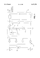
- FIG. 1 is a schematic diagram of the preferred embodiment of the invention.
- a low output conductance control device 1 has a power supply input 3 for receiving a variable DC input voltage.
- a resistor 9 is connected across an output 5 of the device and a control input 7 of the device.
- a reference diode 11 is connected in series with the resistor 9, to another polarity of the input voltage, e.g. which can be connected to ground.
- the device 1 is a low output conductance, depletion mode N-channel metal-oxide-silicon field effect transistor (MOSFET), having its drain connected to the input 3, its source connected to the resistor 9 at output 5, and its gate connected to the junction between the diode 11 and the resistor 9.
- MOSFET metal-oxide-silicon field effect transistor
- the diode 11 is a zener diode, having its anode connected to ground and its cathode connected to the resistor 9 and gate of the MOSFET.
- a MOSFET that was used in a successful laboratory prototype was type ND2410L. This FET provided a constant current via its gate-to-source voltage across the resistor, which had a resistance of 1 megohm. This constant current source supplied a fixed current to the reference zener diode 11 (type 1N4690 was used in the successful prototype which had a breakdown voltage of 5.6 volts).
- the saturation characteristics and low output conductance of the MOSFET as described make it ideal as a current regulator.
- a change in either the input voltage or load impedance changes the regulated current only proportional to its output conductance, which is substantially constant.
- These characteristics provide a near constant current over a wide input voltage range when its drain-to-source voltage exceeds pinch-off of the MOSFET, and it becomes saturated.
- the wide input operating voltage range is important when considering line powered telephone operation.
- the negative gate-to-source voltage performance of the depletion mode FET allows simplified biasing at a very low quiescent current penalty. This low quiescent current is important when considering the on-hook current draw criteria dictated by the regulatory agencies and/or the telephone companies.
- the circuit begins to regulate when the drain voltage of the FET becomes high enough for gate-to-source pinch-off to occur, and for the zener diode to become turned on.
- pinch-off is specified as being in the range from -0.5 volts to -2.5 volts.
- This pinch-off voltage is a constant of the FET, and establishes a very stable constant current through the resistor 9.
- the constant current is also passed through the zener diode, which typically has been found to be about 2 ⁇ A with a 1 megohm resistor across the gate and source of the FET. At 2 ⁇ A the zener voltage of the zener diode 11 is about 5.2 volts.
- the circuit should provide a predetermined period of output voltage (e.g. 5 seconds) when the input supply is interrupted.
- a capacitor 13 is coupled across the series circuit of resistor 9 and diode 11, preferably through a coupling diode 15.
- a logic voltage regulator 17 is preferred to be connected with its inputs across capacitor 13, to supply e.g. regulated 3.3 volts to a circuit to be powered from its output terminal 19 and ground.
- a capacitor 13 value of 33 ⁇ F provided about 7.8 seconds of holdover time, assuming an external current draw of about 15 ⁇ A.
- 7.8 (3.8 V ⁇ 33 ⁇ F)/16 ⁇ A, where the 16 ⁇ A is derived from the 1 ⁇ A drawn by the voltage regulator and 15 ⁇ A is drawn by the external logic circuit.
- the voltage 3.8 is derived from the 5.2 volt zener voltage plus the FET gate-to-source voltage, minus the 0.1 volt forward voltage drop of the diode 15 minus the 3.3 output voltage of the regulator.
- the input voltage is typically supplied from tip T and ring R leads of a telephone line 21.
- a surge protector 23 should be connected across the tip and ring leads.
- a polarity correcting circuit such as a bridge rectifier 23 between the line 21 and the input 3. This provides the circuit with polarity insensitivity from the power supply (e.g. PBX or central office) side.
- the forward voltage of the diodes used in the bridge rectifier decreases the input operating range of the circuit described herein.
- the present invention thus provides a very low on-hook line condition current draw, while providing a regulated voltage that can be used by devices such as dialers which require a supply voltage input sufficient to power logic circuitry, in the presence of a very wide range of supply voltages.
- it can provide a long voltage-maintained holdover time to a powered circuit in the case of interruption of the input power.
Abstract
Description
Claims (16)
Priority Applications (3)
| Application Number | Priority Date | Filing Date | Title |
|---|---|---|---|
| US09/255,461 US6137276A (en) | 1999-02-22 | 1999-02-22 | Onhook telecom power supply regulator mode |
| CA002279072A CA2279072C (en) | 1999-02-22 | 1999-07-29 | Onhook telecom power supply regulator mode |
| GB9918384A GB2347238B (en) | 1999-02-22 | 1999-08-05 | Onhook telecom power supply regulator mode |
Applications Claiming Priority (1)
| Application Number | Priority Date | Filing Date | Title |
|---|---|---|---|
| US09/255,461 US6137276A (en) | 1999-02-22 | 1999-02-22 | Onhook telecom power supply regulator mode |
Publications (1)
| Publication Number | Publication Date |
|---|---|
| US6137276A true US6137276A (en) | 2000-10-24 |
Family
ID=22968431
Family Applications (1)
| Application Number | Title | Priority Date | Filing Date |
|---|---|---|---|
| US09/255,461 Expired - Lifetime US6137276A (en) | 1999-02-22 | 1999-02-22 | Onhook telecom power supply regulator mode |
Country Status (3)
| Country | Link |
|---|---|
| US (1) | US6137276A (en) |
| CA (1) | CA2279072C (en) |
| GB (1) | GB2347238B (en) |
Cited By (18)
| Publication number | Priority date | Publication date | Assignee | Title |
|---|---|---|---|---|
| US6331767B1 (en) * | 1998-02-24 | 2001-12-18 | Lucas Industries, Plc | Power supplies of ECUs |
| GB2372842A (en) * | 2000-11-01 | 2002-09-04 | Edinburgh Comm Ltd | Voltage regulator using a field effect transistor |
| WO2003017683A2 (en) * | 2001-08-16 | 2003-02-27 | James Eric Damschroder | Method and apparatus for creating a visual representation of a portfolio and determining an efficient allocation |
| WO2004082097A1 (en) * | 2003-03-10 | 2004-09-23 | Siemens Ag Österreich | Emergency lighting |
| US20060015543A1 (en) * | 2004-04-03 | 2006-01-19 | Humphrey Richard L | System for delivering propane or other consumable liquid to remotely located storage tanks |
| US20060245217A1 (en) * | 2005-03-17 | 2006-11-02 | The Regents Of The University Of California | Diode-directed solid-state marx generator |
| US20060243347A1 (en) * | 2005-04-02 | 2006-11-02 | Humphrey Richard L | System for monitoring propane or other consumable liquid in remotely located storage tanks |
| US20100241277A1 (en) * | 2004-04-03 | 2010-09-23 | Humphrey Richard L | System for monitoring propane or other consumable liquid in remotely located storage tanks |
| US20110026278A1 (en) * | 2008-04-08 | 2011-02-03 | Mornsun Guangzhou Science & Technology Ltd. | Current-controlled self-oscillating flyback converter with two transistors |
| US20130307519A1 (en) * | 2012-05-16 | 2013-11-21 | Dong-Liang Ren | Switching circuit and electronic device using the same |
| US10058383B2 (en) | 2014-12-01 | 2018-08-28 | Pulse Biosciences, Inc. | Nanoelectroablation control and vaccination |
| US10252050B2 (en) | 2016-05-16 | 2019-04-09 | Pulse Biosciences, Inc. | Pulse applicator |
| US10543357B2 (en) | 2016-09-19 | 2020-01-28 | Pulse Biosciences, Inc. | High voltage connectors for pulse generators |
| US10548665B2 (en) | 2016-02-29 | 2020-02-04 | Pulse Biosciences, Inc. | High-voltage analog circuit pulser with feedback control |
| US10857347B2 (en) | 2017-09-19 | 2020-12-08 | Pulse Biosciences, Inc. | Treatment instrument and high-voltage connectors for robotic surgical system |
| US10874451B2 (en) | 2016-02-29 | 2020-12-29 | Pulse Biosciences, Inc. | High-voltage analog circuit pulser and pulse generator discharge circuit |
| US10946193B2 (en) | 2017-02-28 | 2021-03-16 | Pulse Biosciences, Inc. | Pulse generator with independent panel triggering |
| US11571569B2 (en) | 2019-02-15 | 2023-02-07 | Pulse Biosciences, Inc. | High-voltage catheters for sub-microsecond pulsing |
Families Citing this family (1)
| Publication number | Priority date | Publication date | Assignee | Title |
|---|---|---|---|---|
| US20160013789A1 (en) * | 2014-07-09 | 2016-01-14 | Numerex Corp. | Depletion Mode MOSFET Power Supply |
Citations (2)
| Publication number | Priority date | Publication date | Assignee | Title |
|---|---|---|---|---|
| US4319179A (en) * | 1980-08-25 | 1982-03-09 | Motorola, Inc. | Voltage regulator circuitry having low quiescent current drain and high line voltage withstanding capability |
| US5933337A (en) * | 1996-06-06 | 1999-08-03 | Pioneer Electronics Corporation | Voltage rectifying and smoothing circuit |
Family Cites Families (1)
| Publication number | Priority date | Publication date | Assignee | Title |
|---|---|---|---|---|
| DE3405847C1 (en) * | 1984-02-17 | 1985-08-22 | Siemens AG, 1000 Berlin und 8000 München | Series regulator with a MOSFET power transistor |
-
1999
- 1999-02-22 US US09/255,461 patent/US6137276A/en not_active Expired - Lifetime
- 1999-07-29 CA CA002279072A patent/CA2279072C/en not_active Expired - Fee Related
- 1999-08-05 GB GB9918384A patent/GB2347238B/en not_active Expired - Fee Related
Patent Citations (2)
| Publication number | Priority date | Publication date | Assignee | Title |
|---|---|---|---|---|
| US4319179A (en) * | 1980-08-25 | 1982-03-09 | Motorola, Inc. | Voltage regulator circuitry having low quiescent current drain and high line voltage withstanding capability |
| US5933337A (en) * | 1996-06-06 | 1999-08-03 | Pioneer Electronics Corporation | Voltage rectifying and smoothing circuit |
Cited By (43)
| Publication number | Priority date | Publication date | Assignee | Title |
|---|---|---|---|---|
| US6331767B1 (en) * | 1998-02-24 | 2001-12-18 | Lucas Industries, Plc | Power supplies of ECUs |
| GB2372842A (en) * | 2000-11-01 | 2002-09-04 | Edinburgh Comm Ltd | Voltage regulator using a field effect transistor |
| WO2003017683A2 (en) * | 2001-08-16 | 2003-02-27 | James Eric Damschroder | Method and apparatus for creating a visual representation of a portfolio and determining an efficient allocation |
| WO2003017683A3 (en) * | 2001-08-16 | 2003-10-30 | James Eric Damschroder | Method and apparatus for creating a visual representation of a portfolio and determining an efficient allocation |
| US7466081B2 (en) | 2003-03-10 | 2008-12-16 | Siemens Ag Österreich | Emergency lighting |
| WO2004082097A1 (en) * | 2003-03-10 | 2004-09-23 | Siemens Ag Österreich | Emergency lighting |
| US20060044801A1 (en) * | 2003-03-10 | 2006-03-02 | Siemens Ag, Osterreich | Emergency lighting |
| CN100452611C (en) * | 2003-03-10 | 2009-01-14 | 奥地利西门子股份有限公司 | Emergency lighting |
| US20110173128A1 (en) * | 2004-04-03 | 2011-07-14 | Humphrey Richard L | Apparatus for Monitoring Fluid Levels in a Remotely Located Storage Tank |
| US7937216B2 (en) | 2004-04-03 | 2011-05-03 | Humphrey Richard L | System for monitoring propane or other consumable liquid in remotely located storage tanks |
| US20080033668A1 (en) * | 2004-04-03 | 2008-02-07 | Nas Corp. | System for delivering propane or other consumable liquid to remotely located storage tanks |
| US8504294B2 (en) * | 2004-04-03 | 2013-08-06 | Richard L. Humphrey | Apparatus for monitoring fluid levels in a remotely located storage tank |
| US8340909B2 (en) | 2004-04-03 | 2012-12-25 | Humphrey Richard L | System for monitoring propane or other consumable liquid in remotely located storage tanks |
| US7512488B2 (en) | 2004-04-03 | 2009-03-31 | Humphrey Richard L | System for delivering propane or other consumable liquid to remotely located storage tanks |
| US20090248325A1 (en) * | 2004-04-03 | 2009-10-01 | Humphrey Richard L | Apparatus for monitoring fluid levels in a remotely located storage tank |
| US20100241277A1 (en) * | 2004-04-03 | 2010-09-23 | Humphrey Richard L | System for monitoring propane or other consumable liquid in remotely located storage tanks |
| US8150615B2 (en) | 2004-04-03 | 2012-04-03 | Humphrey Richard L | Apparatus for monitoring fluid levels in a remotely located storage tank |
| US7295919B2 (en) | 2004-04-03 | 2007-11-13 | Nas Corp. | System for delivering propane or other consumable liquid to remotely located storage tanks |
| US8798913B2 (en) | 2004-04-03 | 2014-08-05 | Richard L. Humphrey | System for monitoring propane or other consumable liquid in remotely located storage tanks |
| US7937215B2 (en) | 2004-04-03 | 2011-05-03 | Humphrey Richard L | Apparatus for monitoring fluid levels in a remotely located storage tank |
| US20060015543A1 (en) * | 2004-04-03 | 2006-01-19 | Humphrey Richard L | System for delivering propane or other consumable liquid to remotely located storage tanks |
| US7855904B2 (en) * | 2005-03-17 | 2010-12-21 | Los Alamos National Security, Llc | Apparatus for producing voltage and current pulses |
| US20060245217A1 (en) * | 2005-03-17 | 2006-11-02 | The Regents Of The University Of California | Diode-directed solid-state marx generator |
| US20060243347A1 (en) * | 2005-04-02 | 2006-11-02 | Humphrey Richard L | System for monitoring propane or other consumable liquid in remotely located storage tanks |
| US20110026278A1 (en) * | 2008-04-08 | 2011-02-03 | Mornsun Guangzhou Science & Technology Ltd. | Current-controlled self-oscillating flyback converter with two transistors |
| US20130307519A1 (en) * | 2012-05-16 | 2013-11-21 | Dong-Liang Ren | Switching circuit and electronic device using the same |
| US10058383B2 (en) | 2014-12-01 | 2018-08-28 | Pulse Biosciences, Inc. | Nanoelectroablation control and vaccination |
| US10307207B2 (en) | 2014-12-01 | 2019-06-04 | Pulse Biosciences, Inc. | Nanoelectroablation control and vaccination |
| US10695127B2 (en) | 2014-12-01 | 2020-06-30 | Pulse Biosciences, Inc. | Nanoelectroablation control and vaccination |
| US11051882B2 (en) | 2016-02-29 | 2021-07-06 | Pulse Biosciences, Inc. | High-voltage analog circuit pulser |
| US10548665B2 (en) | 2016-02-29 | 2020-02-04 | Pulse Biosciences, Inc. | High-voltage analog circuit pulser with feedback control |
| US11723712B2 (en) | 2016-02-29 | 2023-08-15 | Pulse Biosciences, Inc. | High-voltage analog circuit pulser and pulse generator discharge circuit |
| US10874451B2 (en) | 2016-02-29 | 2020-12-29 | Pulse Biosciences, Inc. | High-voltage analog circuit pulser and pulse generator discharge circuit |
| US11696800B2 (en) | 2016-02-29 | 2023-07-11 | Pulse Biosciences, Inc. | High-voltage analog circuit pulser |
| US10252050B2 (en) | 2016-05-16 | 2019-04-09 | Pulse Biosciences, Inc. | Pulse applicator |
| US10543357B2 (en) | 2016-09-19 | 2020-01-28 | Pulse Biosciences, Inc. | High voltage connectors for pulse generators |
| US11253695B2 (en) | 2016-09-19 | 2022-02-22 | Pulse Biosciences, Inc. | High voltage connectors and electrodes for pulse generators |
| US10946193B2 (en) | 2017-02-28 | 2021-03-16 | Pulse Biosciences, Inc. | Pulse generator with independent panel triggering |
| US11638815B2 (en) | 2017-09-19 | 2023-05-02 | Pulse Biosciences, Inc. | Treatment instrument and high-voltage connectors for robotic surgical system |
| US10857347B2 (en) | 2017-09-19 | 2020-12-08 | Pulse Biosciences, Inc. | Treatment instrument and high-voltage connectors for robotic surgical system |
| US11167125B2 (en) | 2018-01-16 | 2021-11-09 | Pulse Biosciences, Inc. | Treatment tip with protected electrodes |
| US11571569B2 (en) | 2019-02-15 | 2023-02-07 | Pulse Biosciences, Inc. | High-voltage catheters for sub-microsecond pulsing |
| US11931570B2 (en) | 2019-02-15 | 2024-03-19 | Pulse Biosciences, Inc. | Treating tissue pulsed energy using high-voltage catheters |
Also Published As
| Publication number | Publication date |
|---|---|
| GB2347238A (en) | 2000-08-30 |
| GB2347238B (en) | 2003-02-05 |
| GB9918384D0 (en) | 1999-10-06 |
| CA2279072C (en) | 2003-08-12 |
| CA2279072A1 (en) | 2000-08-22 |
Similar Documents
| Publication | Publication Date | Title |
|---|---|---|
| US6137276A (en) | Onhook telecom power supply regulator mode | |
| US7038522B2 (en) | System and method for redundant power supply connection | |
| US5534768A (en) | Regulated power supply having wide input AC/DC voltage range | |
| US6388433B2 (en) | Linear regulator with low overshooting in transient state | |
| US6501253B2 (en) | Low electrical consumption voltage regulator | |
| US7430131B2 (en) | Start-up circuit for providing a start-up voltage to an application circuit | |
| US4644437A (en) | Telephone subscriber loop overvoltage protection integrated circuit | |
| US4652809A (en) | Switched regulator circuit having an extended duty cycle range | |
| EP0913980A3 (en) | Protection of active telephone line interface circuits | |
| US20030122595A1 (en) | Low voltage amplifying circuit | |
| US9608508B2 (en) | Integrated limiter and active filter | |
| EP0190110B1 (en) | Voltage convertor for telephone terminal equipment | |
| KR880013286A (en) | Emergency D.C., where emergency status is indicated by polarity reversal. Power supply | |
| JPH08503357A (en) | Switching device | |
| US4593213A (en) | Current-limited MOSFET switch | |
| US5825163A (en) | DC-to-DC converter with low supply voltage | |
| CZ20031960A3 (en) | Step-down converter | |
| CN107979285B (en) | Power supply conversion circuit | |
| US6380769B1 (en) | Low voltage output drive circuit | |
| US4731830A (en) | Nonsaturating interface supply | |
| US20050041353A1 (en) | Temperature dependent switching circuit | |
| US5726853A (en) | High voltage protection circuit for telephone test set | |
| US20120002800A1 (en) | Subscriber Line Interface Circuit with DC-DC Converter Current Protection | |
| US4924369A (en) | Regulated blocking converter wherein switch conduction time increases with higher output voltages | |
| CN117134603B (en) | JFET-based high-voltage starting circuit, power converter and power chip |
Legal Events
| Date | Code | Title | Description |
|---|---|---|---|
| AS | Assignment |
Owner name: MITEL, INC., VIRGINIA Free format text: ASSIGNMENT OF ASSIGNORS INTEREST;ASSIGNOR:RUDOLPH, NEAL;REEL/FRAME:009787/0420 Effective date: 19990212 |
|
| AS | Assignment |
Owner name: CANADIAN IMPERIAL BANK OF COMMERCE, AS SECURED PAR Free format text: GRANT OF PATENT SECURITY INTEREST;ASSIGNOR:MITEL INC. (A SUCCESSOR IN INTEREST TO MITEL SEMICONDUCTOR AMERICAS INC.; FORMERLY KNOWN AS GEC PLESSEY SEMICONDUCTORS INC.);REEL/FRAME:010539/0001 Effective date: 19990930 |
|
| STCF | Information on status: patent grant |
Free format text: PATENTED CASE |
|
| AS | Assignment |
Owner name: MITEL CORPORATION, CANADA Free format text: RELEASE BY SECURED PARTY;ASSIGNOR:CANADIAN IMPERIAL BANK OF COMMERCE;REEL/FRAME:011590/0406 Effective date: 20010216 Owner name: MITEL, INC., A DELAWARE CORPORATION, CANADA Free format text: RELEASE BY SECURED PARTY;ASSIGNOR:CANADIAN IMPERIAL BANK OF COMMERCE;REEL/FRAME:011590/0406 Effective date: 20010216 Owner name: MITEL SEMICONDUCTOR, INC., A DELAWARE CORPORATION, Free format text: RELEASE BY SECURED PARTY;ASSIGNOR:CANADIAN IMPERIAL BANK OF COMMERCE;REEL/FRAME:011590/0406 Effective date: 20010216 Owner name: MITEL SEMICONDUCTOR, LIMITED, CANADA Free format text: RELEASE BY SECURED PARTY;ASSIGNOR:CANADIAN IMPERIAL BANK OF COMMERCE;REEL/FRAME:011590/0406 Effective date: 20010216 Owner name: MITEL TELCOM LIMITED CORPORATION, CANADA Free format text: RELEASE BY SECURED PARTY;ASSIGNOR:CANADIAN IMPERIAL BANK OF COMMERCE;REEL/FRAME:011590/0406 Effective date: 20010216 Owner name: MITEL SEMICONDUCTOR AMERICAS, INC., A DELAWARE COR Free format text: RELEASE BY SECURED PARTY;ASSIGNOR:CANADIAN IMPERIAL BANK OF COMMERCE;REEL/FRAME:011590/0406 Effective date: 20010216 |
|
| FPAY | Fee payment |
Year of fee payment: 4 |
|
| AS | Assignment |
Owner name: MITEL NETWORKS CORPORATION, CANADA Free format text: ASSIGNMENT OF ASSIGNORS INTEREST;ASSIGNOR:MITEL NETWORKS, INC.;REEL/FRAME:016256/0797 Effective date: 20050426 Owner name: MITEL NETWORKS, INC., DELAWARE Free format text: CHANGE OF NAME;ASSIGNOR:MITEL, INC.;REEL/FRAME:016256/0771 Effective date: 20010226 |
|
| AS | Assignment |
Owner name: MITEL NETWORKS CORPORATION,CANADA Free format text: SECURITY AGREEMENT;ASSIGNOR:HIGHBRIDGE INTERNATIONAL LLC;REEL/FRAME:016345/0236 Effective date: 20050427 Owner name: MITEL NETWORKS CORPORATION, CANADA Free format text: SECURITY AGREEMENT;ASSIGNOR:HIGHBRIDGE INTERNATIONAL LLC;REEL/FRAME:016345/0236 Effective date: 20050427 |
|
| AS | Assignment |
Owner name: BNY TRUST COMPANY OF CANADA, TRUST COMPANY OF CANA Free format text: SECURITY AGREEMENT;ASSIGNOR:MITEL NETWORKS CORPORATION, A CORPORATION OF CANADA;REEL/FRAME:016891/0959 Effective date: 20050427 |
|
| AS | Assignment |
Owner name: MORGAN STANLEY & CO. INCORPORATED, NEW YORK Free format text: SECURITY AGREEMENT;ASSIGNOR:MITEL NETWORKS CORPORATION;REEL/FRAME:019817/0847 Effective date: 20070816 Owner name: MORGAN STANLEY & CO. INCORPORATED, NEW YORK Free format text: SECURITY AGREEMENT;ASSIGNOR:MITEL NETWORKS CORPORATION;REEL/FRAME:019817/0881 Effective date: 20070816 Owner name: MORGAN STANLEY & CO. INCORPORATED,NEW YORK Free format text: SECURITY AGREEMENT;ASSIGNOR:MITEL NETWORKS CORPORATION;REEL/FRAME:019817/0847 Effective date: 20070816 Owner name: MORGAN STANLEY & CO. INCORPORATED,NEW YORK Free format text: SECURITY AGREEMENT;ASSIGNOR:MITEL NETWORKS CORPORATION;REEL/FRAME:019817/0881 Effective date: 20070816 |
|
| FPAY | Fee payment |
Year of fee payment: 8 |
|
| AS | Assignment |
Owner name: MITEL NETWORKS CORPORATION, CANADA Free format text: RELEASE & DISCHARGE OF SECURITY INTEREST;ASSIGNOR:HIGHBRIDGE INTERNATIONAL LLC/BNY TRUST COMPANY OF CANADA;REEL/FRAME:021794/0510 Effective date: 20080304 Owner name: MITEL NETWORKS CORPORATION,CANADA Free format text: RELEASE & DISCHARGE OF SECURITY INTEREST;ASSIGNOR:HIGHBRIDGE INTERNATIONAL LLC/BNY TRUST COMPANY OF CANADA;REEL/FRAME:021794/0510 Effective date: 20080304 |
|
| FPAY | Fee payment |
Year of fee payment: 12 |
|
| AS | Assignment |
Owner name: MITEL NETWORKS CORPORATION, CANADA Free format text: RELEASE OF SECURITY INTEREST IN PATENTS;ASSIGNOR:WILMINGTON TRUST, NATIONAL ASSOCIATION FKA WILMINGTON TRUST FSB/MORGAN STANLEY & CO. INCORPORATED;REEL/FRAME:030165/0776 Effective date: 20130227 |
|
| AS | Assignment |
Owner name: BANK OF AMERICA, N.A., AS COLLATERAL AGENT, TEXAS Free format text: SECURITY AGREEMENT;ASSIGNOR:MITEL NETWORKS CORPORATION;REEL/FRAME:030186/0894 Effective date: 20130227 Owner name: WILMINGTON TRUST, N.A., AS SECOND COLLATERAL AGENT Free format text: SECURITY INTEREST;ASSIGNOR:MITEL NETWORKS CORPORATION;REEL/FRAME:030201/0743 Effective date: 20130227 |
|
| AS | Assignment |
Owner name: MITEL NETWORKS CORPORATION, CANADA Free format text: RELEASE BY SECURED PARTY;ASSIGNORS:BANK OF NEW YORK MELLON, THE;MORGAN STANLEY & CO. INCORPORATED;MORGAN STANLEY SENIOR FUNDING, INC.;REEL/FRAME:030264/0470 Effective date: 20130227 |
|
| AS | Assignment |
Owner name: MITEL NETWORKS CORPORATION, CANADA Free format text: RELEASE BY SECURED PARTY;ASSIGNOR:WILMINGTON TRUST, NATIONAL ASSOCIATION;REEL/FRAME:032167/0464 Effective date: 20140131 Owner name: MITEL US HOLDINGS, INC., ARIZONA Free format text: RELEASE BY SECURED PARTY;ASSIGNOR:WILMINGTON TRUST, NATIONAL ASSOCIATION;REEL/FRAME:032167/0464 Effective date: 20140131 |
|
| AS | Assignment |
Owner name: MITEL NETWORKS CORPORATION, CANADA Free format text: RELEASE BY SECURED PARTY;ASSIGNOR:BANK OF AMERICA, N.A.;REEL/FRAME:032210/0245 Effective date: 20140131 Owner name: MITEL US HOLDINGS, INC., ARIZONA Free format text: RELEASE BY SECURED PARTY;ASSIGNOR:BANK OF AMERICA, N.A.;REEL/FRAME:032210/0245 Effective date: 20140131 |
|
| AS | Assignment |
Owner name: JEFFERIES FINANCE LLC, AS THE COLLATERAL AGENT, NE Free format text: SECURITY AGREEMENT;ASSIGNORS:MITEL US HOLDINGS, INC.;MITEL NETWORKS CORPORATION;AASTRA USA INC.;REEL/FRAME:032264/0760 Effective date: 20140131 |
|
| AS | Assignment |
Owner name: MITEL US HOLDINGS, INC., ARIZONA Free format text: RELEASE BY SECURED PARTY;ASSIGNOR:JEFFERIES FINANCE LLC, AS THE COLLATERAL AGENT;REEL/FRAME:035562/0157 Effective date: 20150429 Owner name: MITEL COMMUNICATIONS INC. FKA AASTRA USA INC., TEX Free format text: RELEASE BY SECURED PARTY;ASSIGNOR:JEFFERIES FINANCE LLC, AS THE COLLATERAL AGENT;REEL/FRAME:035562/0157 Effective date: 20150429 Owner name: MITEL NETWORKS CORPORATION, CANADA Free format text: RELEASE BY SECURED PARTY;ASSIGNOR:JEFFERIES FINANCE LLC, AS THE COLLATERAL AGENT;REEL/FRAME:035562/0157 Effective date: 20150429 |
|
| AS | Assignment |
Owner name: BANK OF AMERICA, N.A.(ACTING THROUGH ITS CANADA BR Free format text: SECURITY INTEREST;ASSIGNOR:MITEL NETWORKS CORPORATION;REEL/FRAME:035783/0540 Effective date: 20150429 |
|
| AS | Assignment |
Owner name: CITIZENS BANK, N.A., MASSACHUSETTS Free format text: SECURITY INTEREST;ASSIGNOR:MITEL NETWORKS CORPORATION;REEL/FRAME:042107/0378 Effective date: 20170309 |
|
| AS | Assignment |
Owner name: MITEL BUSINESS SYSTEMS, INC., ARIZONA Free format text: RELEASE BY SECURED PARTY;ASSIGNORS:BANK OF AMERICA, N.A., AS COLLATERAL AGENT;BANK OF AMERICA, N.A., (ACTING THROUGH ITS CANADA BRANCH), AS CANADIAN COLLATERAL AGENT;REEL/FRAME:042244/0461 Effective date: 20170309 Owner name: MITEL NETWORKS CORPORATION, CANADA Free format text: RELEASE BY SECURED PARTY;ASSIGNORS:BANK OF AMERICA, N.A., AS COLLATERAL AGENT;BANK OF AMERICA, N.A., (ACTING THROUGH ITS CANADA BRANCH), AS CANADIAN COLLATERAL AGENT;REEL/FRAME:042244/0461 Effective date: 20170309 Owner name: MITEL US HOLDINGS, INC., ARIZONA Free format text: RELEASE BY SECURED PARTY;ASSIGNORS:BANK OF AMERICA, N.A., AS COLLATERAL AGENT;BANK OF AMERICA, N.A., (ACTING THROUGH ITS CANADA BRANCH), AS CANADIAN COLLATERAL AGENT;REEL/FRAME:042244/0461 Effective date: 20170309 Owner name: MITEL COMMUNICATIONS, INC., TEXAS Free format text: RELEASE BY SECURED PARTY;ASSIGNORS:BANK OF AMERICA, N.A., AS COLLATERAL AGENT;BANK OF AMERICA, N.A., (ACTING THROUGH ITS CANADA BRANCH), AS CANADIAN COLLATERAL AGENT;REEL/FRAME:042244/0461 Effective date: 20170309 Owner name: MITEL NETWORKS, INC., ARIZONA Free format text: RELEASE BY SECURED PARTY;ASSIGNORS:BANK OF AMERICA, N.A., AS COLLATERAL AGENT;BANK OF AMERICA, N.A., (ACTING THROUGH ITS CANADA BRANCH), AS CANADIAN COLLATERAL AGENT;REEL/FRAME:042244/0461 Effective date: 20170309 Owner name: MITEL (DELAWARE), INC., ARIZONA Free format text: RELEASE BY SECURED PARTY;ASSIGNORS:BANK OF AMERICA, N.A., AS COLLATERAL AGENT;BANK OF AMERICA, N.A., (ACTING THROUGH ITS CANADA BRANCH), AS CANADIAN COLLATERAL AGENT;REEL/FRAME:042244/0461 Effective date: 20170309 |
|
| AS | Assignment |
Owner name: MITEL NETWORKS CORPORATION, CANADA Free format text: RELEASE BY SECURED PARTY;ASSIGNOR:CITIZENS BANK, N.A.;REEL/FRAME:048096/0785 Effective date: 20181130 |
|
| AS | Assignment |
Owner name: CREDIT SUISSE AG, CAYMAN ISLANDS BRANCH, AS COLLATERAL AGENT, NEW YORK Free format text: SECURITY INTEREST;ASSIGNOR:MITEL NETWORKS ULC;REEL/FRAME:047741/0674 Effective date: 20181205 Owner name: CREDIT SUISSE AG, CAYMAN ISLANDS BRANCH, AS COLLATERAL AGENT, NEW YORK Free format text: SECURITY INTEREST;ASSIGNOR:MITEL NETWORKS ULC;REEL/FRAME:047741/0704 Effective date: 20181205 Owner name: CREDIT SUISSE AG, CAYMAN ISLANDS BRANCH, AS COLLAT Free format text: SECURITY INTEREST;ASSIGNOR:MITEL NETWORKS ULC;REEL/FRAME:047741/0704 Effective date: 20181205 Owner name: CREDIT SUISSE AG, CAYMAN ISLANDS BRANCH, AS COLLAT Free format text: SECURITY INTEREST;ASSIGNOR:MITEL NETWORKS ULC;REEL/FRAME:047741/0674 Effective date: 20181205 |