US6138859A - Fuel tank assembly - Google Patents
Fuel tank assembly Download PDFInfo
- Publication number
- US6138859A US6138859A US09/425,569 US42556999A US6138859A US 6138859 A US6138859 A US 6138859A US 42556999 A US42556999 A US 42556999A US 6138859 A US6138859 A US 6138859A
- Authority
- US
- United States
- Prior art keywords
- baffle
- fuel tank
- cradle
- half shell
- tank assembly
- Prior art date
- Legal status (The legal status is an assumption and is not a legal conclusion. Google has not performed a legal analysis and makes no representation as to the accuracy of the status listed.)
- Expired - Lifetime
Links
Images

Classifications
-
- B—PERFORMING OPERATIONS; TRANSPORTING
- B60—VEHICLES IN GENERAL
- B60K—ARRANGEMENT OR MOUNTING OF PROPULSION UNITS OR OF TRANSMISSIONS IN VEHICLES; ARRANGEMENT OR MOUNTING OF PLURAL DIVERSE PRIME-MOVERS IN VEHICLES; AUXILIARY DRIVES FOR VEHICLES; INSTRUMENTATION OR DASHBOARDS FOR VEHICLES; ARRANGEMENTS IN CONNECTION WITH COOLING, AIR INTAKE, GAS EXHAUST OR FUEL SUPPLY OF PROPULSION UNITS IN VEHICLES
- B60K15/00—Arrangement in connection with fuel supply of combustion engines or other fuel consuming energy converters, e.g. fuel cells; Mounting or construction of fuel tanks
- B60K15/03—Fuel tanks
- B60K15/077—Fuel tanks with means modifying or controlling distribution or motion of fuel, e.g. to prevent noise, surge, splash or fuel starvation
-
- B—PERFORMING OPERATIONS; TRANSPORTING
- B60—VEHICLES IN GENERAL
- B60K—ARRANGEMENT OR MOUNTING OF PROPULSION UNITS OR OF TRANSMISSIONS IN VEHICLES; ARRANGEMENT OR MOUNTING OF PLURAL DIVERSE PRIME-MOVERS IN VEHICLES; AUXILIARY DRIVES FOR VEHICLES; INSTRUMENTATION OR DASHBOARDS FOR VEHICLES; ARRANGEMENTS IN CONNECTION WITH COOLING, AIR INTAKE, GAS EXHAUST OR FUEL SUPPLY OF PROPULSION UNITS IN VEHICLES
- B60K15/00—Arrangement in connection with fuel supply of combustion engines or other fuel consuming energy converters, e.g. fuel cells; Mounting or construction of fuel tanks
- B60K15/03—Fuel tanks
- B60K15/073—Tank construction specially adapted to the vehicle
-
- B—PERFORMING OPERATIONS; TRANSPORTING
- B60—VEHICLES IN GENERAL
- B60K—ARRANGEMENT OR MOUNTING OF PROPULSION UNITS OR OF TRANSMISSIONS IN VEHICLES; ARRANGEMENT OR MOUNTING OF PLURAL DIVERSE PRIME-MOVERS IN VEHICLES; AUXILIARY DRIVES FOR VEHICLES; INSTRUMENTATION OR DASHBOARDS FOR VEHICLES; ARRANGEMENTS IN CONNECTION WITH COOLING, AIR INTAKE, GAS EXHAUST OR FUEL SUPPLY OF PROPULSION UNITS IN VEHICLES
- B60K15/00—Arrangement in connection with fuel supply of combustion engines or other fuel consuming energy converters, e.g. fuel cells; Mounting or construction of fuel tanks
- B60K15/03—Fuel tanks
- B60K15/03177—Fuel tanks made of non-metallic material, e.g. plastics, or of a combination of non-metallic and metallic material
-
- B—PERFORMING OPERATIONS; TRANSPORTING
- B60—VEHICLES IN GENERAL
- B60K—ARRANGEMENT OR MOUNTING OF PROPULSION UNITS OR OF TRANSMISSIONS IN VEHICLES; ARRANGEMENT OR MOUNTING OF PLURAL DIVERSE PRIME-MOVERS IN VEHICLES; AUXILIARY DRIVES FOR VEHICLES; INSTRUMENTATION OR DASHBOARDS FOR VEHICLES; ARRANGEMENTS IN CONNECTION WITH COOLING, AIR INTAKE, GAS EXHAUST OR FUEL SUPPLY OF PROPULSION UNITS IN VEHICLES
- B60K15/00—Arrangement in connection with fuel supply of combustion engines or other fuel consuming energy converters, e.g. fuel cells; Mounting or construction of fuel tanks
- B60K15/03—Fuel tanks
- B60K2015/03328—Arrangements or special measures related to fuel tanks or fuel handling
- B60K2015/0344—Arrangements or special measures related to fuel tanks or fuel handling comprising baffles
-
- B—PERFORMING OPERATIONS; TRANSPORTING
- B60—VEHICLES IN GENERAL
- B60K—ARRANGEMENT OR MOUNTING OF PROPULSION UNITS OR OF TRANSMISSIONS IN VEHICLES; ARRANGEMENT OR MOUNTING OF PLURAL DIVERSE PRIME-MOVERS IN VEHICLES; AUXILIARY DRIVES FOR VEHICLES; INSTRUMENTATION OR DASHBOARDS FOR VEHICLES; ARRANGEMENTS IN CONNECTION WITH COOLING, AIR INTAKE, GAS EXHAUST OR FUEL SUPPLY OF PROPULSION UNITS IN VEHICLES
- B60K15/00—Arrangement in connection with fuel supply of combustion engines or other fuel consuming energy converters, e.g. fuel cells; Mounting or construction of fuel tanks
- B60K15/03—Fuel tanks
- B60K15/077—Fuel tanks with means modifying or controlling distribution or motion of fuel, e.g. to prevent noise, surge, splash or fuel starvation
- B60K2015/0775—Fuel tanks with means modifying or controlling distribution or motion of fuel, e.g. to prevent noise, surge, splash or fuel starvation for reducing movement or slash noise of fuel
-
- Y—GENERAL TAGGING OF NEW TECHNOLOGICAL DEVELOPMENTS; GENERAL TAGGING OF CROSS-SECTIONAL TECHNOLOGIES SPANNING OVER SEVERAL SECTIONS OF THE IPC; TECHNICAL SUBJECTS COVERED BY FORMER USPC CROSS-REFERENCE ART COLLECTIONS [XRACs] AND DIGESTS
- Y10—TECHNICAL SUBJECTS COVERED BY FORMER USPC
- Y10T—TECHNICAL SUBJECTS COVERED BY FORMER US CLASSIFICATION
- Y10T137/00—Fluid handling
- Y10T137/8593—Systems
- Y10T137/86187—Plural tanks or compartments connected for serial flow
- Y10T137/86212—Plural compartments formed by baffles
-
- Y—GENERAL TAGGING OF NEW TECHNOLOGICAL DEVELOPMENTS; GENERAL TAGGING OF CROSS-SECTIONAL TECHNOLOGIES SPANNING OVER SEVERAL SECTIONS OF THE IPC; TECHNICAL SUBJECTS COVERED BY FORMER USPC CROSS-REFERENCE ART COLLECTIONS [XRACs] AND DIGESTS
- Y10—TECHNICAL SUBJECTS COVERED BY FORMER USPC
- Y10T—TECHNICAL SUBJECTS COVERED BY FORMER US CLASSIFICATION
- Y10T137/00—Fluid handling
- Y10T137/8593—Systems
- Y10T137/86187—Plural tanks or compartments connected for serial flow
- Y10T137/86228—With communicating opening in common walls of tanks or compartments
Definitions
- the present invention relates generally to fuel tanks for vehicles and, more particularly, to a fuel tank assembly for a vehicle.
- a fuel tank such as a metal or plastic fuel tank in a vehicle to hold fuel to be used by an engine of the vehicle.
- the fuel tanks have a shell made from a first half shell and a second half shell that are joined together.
- fuel tanks utilize baffles inside the tank to stiffen the tank shell for controlling the amount of shell movement (volume change in tank), and/or as an obstruction to minimize sloshing of the fuel, during operation of the vehicle.
- Baffles may be used in either metal or plastic fuel tanks.
- a baffle is usually a sheet of the same material as the tank that, most often, is mounted inside the tank at or near ninety (90) degrees to the tank wall.
- the baffle may be attached to the shell along edges, at strategic points within the tank or fit in grooves.
- the baffle may be attached to the tank shell when the relative temperatures between the tank shell and baffle are significantly different, causing, after cooling to a common temperature, stress due to different amounts of shrinkage. Additionally, when a fuel tank containing a baffle is subjected to a force significant enough to cause the tank shell to deflect inward at or near a baffle edge, the baffle may penetrate the shell, resulting in failure of the tank. Such failures result from the baffle behaving as a rigid structure that does not stretch, buckle, or deflect in a fashion similar to the tank shell.
- a fuel tank assembly for a vehicle that incorporates a baffle that is different from existing baffles and offers compliance to shrinking of the tank shell during manufacture. It is also desirable to provide a fuel tank assembly for a vehicle that incorporates a baffle that can offer directional properties (e.g., stiffness) to suit the function of each tank configuration. It is further desirable to provide a fuel tank assembly for a vehicle that incorporates a baffle that offers compliance to excessive forces that may be applied to the tank during operation.
- the present invention is a fuel tank assembly for a vehicle including a tank shell having a first half shell and a second half shell.
- the fuel tank assembly also includes a plurality of column supports disposed between and attached to the first half shell and the second half shell.
- the fuel tank assembly further includes a cradle baffle disposed between the first half shell and the second half shell and attached to the column supports.
- the cradle baffle has at least one compliant joint disposed between a pair of the column supports to allow the cradle baffle to distort when a force is applied to the tank shell.
- a fuel tank assembly is provided for a vehicle that incorporates a new baffle.
- the fuel tank assembly incorporates a baffle that offers compliance to shrinking of the tank shell during manufacture and to excessive forces that may be applied to the fuel tank during operation.
- the fuel tank assembly has a baffle incorporating a compliant joint can be directional to suit the function of each tank configuration.
- the fuel tank assembly has a baffle that is directional in nature that allows the design to be applied so that the baffle does not offer significant stiffness in directions where structural stiffness is not needed for fuel tank performance.
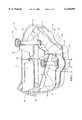
- FIG. 1 is an exploded perspective view of a fuel tank assembly, according to the present invention.
- FIG. 2 is a perspective view of a portion of the fuel tank assembly of FIG. 1 with an upper half shell removed.
- the fuel tank assembly 10 includes a tank shell 12.
- the tank shell 12 is of a saddle type.
- the tank shell 12 includes a first or lower half shell 14 and a second or upper half shell 16.
- the lower half shell 14 has a base wall 18 and a side wall 20 around a periphery of the base wall 18 and extending generally perpendicular thereto.
- the side wall 20 has a flange 22 extending outwardly and generally perpendicular thereto.
- the upper half shell 16 has a base wall 24 and a side wall 26 around a periphery of the base wall 24 and extending generally perpendicular thereto.
- the side wall 26 has a flange 28 extending outwardly and generally perpendicular thereto.
- the flanges 22 and 28 of the lower half shell 14 and upper half shell 16, respectively, are joined together by suitable means such as by welding.
- the lower half shell 14 and upper half shell 16 are made of a rigid material such as plastic. It should be appreciated that the tank shell 12 is conventional and known in the art.
- the fuel tank assembly 10 also includes at least one, preferably a plurality of column supports 30 disposed between the lower half shell 14 and upper half shell 16.
- the column supports 30 are generally tubular in shape with a generally circular cross-section.
- the column supports 30 are made of a plastic material, preferably the same material as the tank shell 12.
- the column supports 30 have a first end 32 extending radially outwardly for attachment to the lower half shell 14 and a second end 34 extending radially outwardly for attachment to the upper half shell 16. As illustrated, the first ends 32 of the column supports 30 are attached to the lower half shell 14. It should be appreciated that the second ends 34 of the column supports 30 are attached to the upper half shell 16.
- the fuel tank assembly 10 also includes a cradle baffle, generally indicated at 36, disposed between the lower half shell 14 and upper half shell 16.
- the cradle baffle 36 includes a cradle span 38 extending laterally.
- the cradle span 38 has a pair of first members 40 extending laterally and a plurality of second members 42 extending generally perpendicular to and interconnecting the first members 40.
- the cradle baffle 36 includes at least one, preferably a plurality of baffle sections 44,46,48 extending between each end of the cradle span 38 and the column supports 30.
- the cradle baffle 36 has a first baffle section 44 extending laterally from one of the first members 40 to one of the column supports 30 and a second baffle section 46 extending laterally on the same side from the other one of the first members 40 to another one of the column supports 30.
- the cradle baffle 36 has a third baffle section 48 extending between the first baffle section 44 and second baffle section 46.
- the cradle baffle 36 includes an extension 50 extending from the intersection of the second baffle section 46 and third baffle section 48 and having a flange/support 52 to hold a part, such as a valve-tank pressure control) in a proper location in the tank shell 12.
- the baffle sections 44,46,48 may be secured to the column supports 30 by suitable means such as welding.
- the cradle baffle 36 is made of a rigid material, preferably the same material as the tank shell 12.
- the cradle baffle 36 resists sloshing of fuel in the tank shell 12 and supports internal tank components. It should be appreciated that the tank components such as pumps, fuel lines, senders and other components that normally attach to the cradle baffle 36 are not shown. It should also be appreciated that the length of the baffle sections 44,46,48 may be varied. It should further be appreciated that only the column supports 30 are structurally attached to the base walls 18 and 24 of the tank shell 12.
- Each baffle section 44,46,48 includes a compliant joint 54 disposed between the ends thereof.
- the compliant joint 54 has a geometry of a predetermined shape such as a generally "S" shape cross-section similar to a mathematical sine function.
- the geometry of the compliant joint 54 can be varied to accommodate different tank shells and operational behaviors.
- the compliant joint 54 may have a geometry of "S", “Z”, “U”, “W”, “V”, “O”, “M”, “C”, “L” or the like.
- the compliant joint 54 can be optimized by controlling the depth, thickness, height, length, radii of shape and location of the compliant joint 54 in the baffle section 44,46,48.
- the compliant joint 54 and baffle sections 44,46,48 are integral, unitary and formed as one-piece. It should be appreciated that the cradle baffle 36 and compliant joints 54 control the stiffness contributed to the tank shell 12 by the baffle sections 44,46,48 to minimize stresses introduced to the tank shell 12 during manufacturing and operation of the fuel tank assembly 10. It should also be appreciated that the cradle baffle 36 is a monolithic structure being integral, unitary and one-piece.
- the cradle baffle 36 When manufacturing the fuel tank assembly 10, the cradle baffle 36 is inserted at a significantly lower temperature inside the heated lower half shell 14, which is near the melt point of the plastic.
- the upper half shell 16 is lowered onto the lower half shell 14 and the flanges 22 and 28 are welded together, sealing an interface, and forming the fuel tank assembly 10.
- the column supports 30 are also welded to the base walls 18 and 24 of the lower and upper half shells 14 and 16.
- the lower and upper half shells 14 and 16 shrink more than the cradle baffle 36. As this shrinkage occurs, the compliant joints 54 will flex, changing the shape of the compliant joint 54, with minimum force. This allows the baffle sections 44,46,48 to follow the shrinkage of the tank shell 12 without offering significant resistance force or stress in the column supports 30 or welds of the column supports 30 to the tank shell 12.
Abstract
Description
Claims (20)
Priority Applications (1)
| Application Number | Priority Date | Filing Date | Title |
|---|---|---|---|
| US09/425,569 US6138859A (en) | 1999-06-08 | 1999-10-20 | Fuel tank assembly |
Applications Claiming Priority (2)
| Application Number | Priority Date | Filing Date | Title |
|---|---|---|---|
| US13825299P | 1999-06-08 | 1999-06-08 | |
| US09/425,569 US6138859A (en) | 1999-06-08 | 1999-10-20 | Fuel tank assembly |
Publications (1)
| Publication Number | Publication Date |
|---|---|
| US6138859A true US6138859A (en) | 2000-10-31 |
Family
ID=26836027
Family Applications (1)
| Application Number | Title | Priority Date | Filing Date |
|---|---|---|---|
| US09/425,569 Expired - Lifetime US6138859A (en) | 1999-06-08 | 1999-10-20 | Fuel tank assembly |
Country Status (1)
| Country | Link |
|---|---|
| US (1) | US6138859A (en) |
Cited By (75)
| Publication number | Priority date | Publication date | Assignee | Title |
|---|---|---|---|---|
| US6338420B1 (en) * | 1999-06-08 | 2002-01-15 | Delphi Technologies, Inc. | Motor vehicle fuel tank and method |
| WO2002014097A2 (en) * | 2000-08-11 | 2002-02-21 | Visteon Global Technologies, Inc. | Low hydrocarbon emission fuel tank with internal components |
| US6454114B2 (en) * | 2000-04-13 | 2002-09-24 | Daimlerchrysler Ag | Plastic fuel tank and method for producing same |
| US6568556B1 (en) | 2002-09-23 | 2003-05-27 | Visteon Global Technologies, Inc. | Fuel tank baffle |
| US6661339B2 (en) | 2000-01-24 | 2003-12-09 | Nextreme, L.L.C. | High performance fuel tank |
| US20040011786A1 (en) * | 2001-04-20 | 2004-01-22 | Wade Wayne Allen | Thermoplastic molded tank |
| US6761380B2 (en) | 2002-05-07 | 2004-07-13 | Delphi Technologies, Inc. | Filler neck assembly for fuel tank |
| US20040188447A1 (en) * | 2002-01-23 | 2004-09-30 | Todd Bolzer | Underground storage tank |
| US6843384B2 (en) * | 2001-01-31 | 2005-01-18 | Ti Group Automotive Systems Technology Center Gmbh | Fuel tank |
| US20060102634A1 (en) * | 2004-11-15 | 2006-05-18 | Visteon Global Technologies, Inc. | Fuel tank system having enhanced durability and reduced permeation |
| US20070028968A1 (en) * | 2005-08-04 | 2007-02-08 | Sanderson Rod M | Reservoir assembly |
| US20070228050A1 (en) * | 2006-04-03 | 2007-10-04 | Nissan Motor Co., Ltd. | Fuel tank structure |
| US20080083761A1 (en) * | 2004-12-21 | 2008-04-10 | Volvo Lastvagnar Ab | Reservoir For Running Material |
| US20090139994A1 (en) * | 2007-11-30 | 2009-06-04 | Fts Co., Ltd. | Automotive fuel tank |
| JP2009132296A (en) * | 2007-11-30 | 2009-06-18 | Fts:Kk | Fuel tank for automobile |
| US20090189384A1 (en) * | 2008-01-29 | 2009-07-30 | Doug Schoen | Fuel tank shell with structural support |
| US20090206097A1 (en) * | 2008-02-18 | 2009-08-20 | Kautex Textron Gmbh & Co. Kg | Fuel tank for a motor vehicle of thermoplastic material |
| US20090250458A1 (en) * | 2004-12-15 | 2009-10-08 | Inergy Auto. Systems Research (Societe Anonyme) | Method for manufacturing a plastic fuel tank with improved creep strength |
| WO2010023267A1 (en) * | 2008-09-01 | 2010-03-04 | Inergy Automotive Systems Research (Société Anonyme) | Plastic fuel tank comprising a noise reduction baffle and process for manufacturing it |
| WO2010122065A1 (en) * | 2009-04-23 | 2010-10-28 | Inergy Automotive Systems Research (Société Anonyme) | Plastic fuel tank with improved creep resistance and method for the manufacture thereof |
| WO2011018410A1 (en) * | 2009-08-11 | 2011-02-17 | Magna Steyr Fuel Systems Gesmbh | Fuel container for motor vehicles with tie rod |
| US7948371B2 (en) | 2000-01-24 | 2011-05-24 | Nextreme Llc | Material handling apparatus with a cellular communications device |
| US20110226777A1 (en) * | 2010-03-16 | 2011-09-22 | Fts Co., Ltd. | Fuel tank for motor vehicle |
| US8077040B2 (en) | 2000-01-24 | 2011-12-13 | Nextreme, Llc | RF-enabled pallet |
| US20120024868A1 (en) * | 2010-07-28 | 2012-02-02 | Dr. Ing. H.C.F. Porsche Aktiengesellschaft | Fuel tank |
| WO2012139962A1 (en) * | 2011-04-12 | 2012-10-18 | Inergy Automotive Systems Research (Société Anonyme) | Fuel tank with improved mechanical resistance |
| EP2527180A1 (en) * | 2011-05-25 | 2012-11-28 | Inergy Automotive Systems Research (Société Anonyme) | Fuel tank with improved creep resistance and method for manufacturing it |
| EP2537696A1 (en) * | 2011-06-24 | 2012-12-26 | Magna Steyr Fuel Systems GesmbH | Fuel reservoir for a motor vehicle |
| DE102011115384A1 (en) * | 2011-10-10 | 2013-04-11 | Kautex Textron Gmbh & Co. Kg | The working fluid container |
| US20130240539A1 (en) * | 2010-06-14 | 2013-09-19 | Ford Global Technologies, Llc | Compliance structure for a distensible fuel tank |
| US8596488B2 (en) * | 2011-09-30 | 2013-12-03 | Kobelco Construction Machinery Co., Ltd. | Tank for construction machine |
| US8657051B2 (en) | 2010-06-14 | 2014-02-25 | Ford Global Technologies, Llc | Lattice structure for a distensible fuel tank |
| DE102012108851A1 (en) * | 2012-09-20 | 2014-03-20 | Veritas Ag | Liquid tank with a baffle |
| US20140117023A1 (en) * | 2012-10-29 | 2014-05-01 | Ti Automotive Technology Center Gmbh | Self-adjusting connector |
| US20140144914A1 (en) * | 2010-12-03 | 2014-05-29 | Jeffrey Yager | Deployable fuel tank baffle and fuel tank system |
| WO2014112236A1 (en) * | 2013-01-15 | 2014-07-24 | トヨタ自動車株式会社 | Fuel tank structure |
| WO2014131686A2 (en) * | 2013-02-27 | 2014-09-04 | Kautex Textron Gmbh & Co. Kg | Fuel container |
| WO2014131685A2 (en) * | 2013-02-27 | 2014-09-04 | Kautex Textron Gmbh & Co. Kg | Fuel tank |
| US8881855B2 (en) | 2010-06-14 | 2014-11-11 | Ford Global Technologies, Llc | Lattice structure for a distensible fuel tank |
| WO2014199222A1 (en) * | 2013-06-14 | 2014-12-18 | Toyota Jidosha Kabushiki Kaisha | Fuel tank |
| US20150014307A1 (en) * | 2013-07-10 | 2015-01-15 | Magna Steyr Fuel Systems Gesmbh | Tie rod, plastic tank and method for manufactoring a plastic tank |
| US20150083719A1 (en) * | 2012-04-27 | 2015-03-26 | Kautex Textron Gmbh & Co. Kg | Extrusion-blow-molded fuel tank of thermoplastic material and method for the production thereof |
| JP2015058724A (en) * | 2013-09-17 | 2015-03-30 | 株式会社Fts | Fuel tank for automobile |
| JP2015085915A (en) * | 2013-11-01 | 2015-05-07 | 八千代工業株式会社 | Wave eliminating plate fixing structure in fuel tank |
| US20150217635A1 (en) * | 2013-02-07 | 2015-08-06 | Fts Co., Ltd. | Automobile fuel tank |
| US20150224871A1 (en) * | 2009-09-18 | 2015-08-13 | Ti Automotive Technology Center Gmbh | Fuel Tank Support |
| US20150232227A1 (en) * | 2006-07-03 | 2015-08-20 | Kautex Textron Gmbh & Co. Kg | Container of thermoplastic material |
| JP2015157511A (en) * | 2014-02-21 | 2015-09-03 | トヨタ自動車株式会社 | resin fuel tank |
| US20150258887A1 (en) * | 2012-08-28 | 2015-09-17 | Yapp Automotive Parts Co., Ltd | Automobile Urea Tank and Formatting Method Thereof |
| US20160009171A1 (en) * | 2014-07-14 | 2016-01-14 | Aethra Sistemas Automotivos S/A | High Pressure Fuel Tank Manufactured From High-Strength Steel Sheets or Advanced High-Strength Steel Sheets With Organometallic Coat |
| WO2016066333A1 (en) * | 2014-10-30 | 2016-05-06 | Volkswagen Aktiengesellschaft | Fuel tank for a motor vehicle |
| US9694672B2 (en) | 2010-06-14 | 2017-07-04 | Ford Global Technologies, Llc | Compliance structure for a distensible fuel tank |
| EP3238973A1 (en) * | 2016-04-28 | 2017-11-01 | Plastic Omnium Advanced Innovation and Research | Tank reinforcement with integrated baffle |
| DE102016008341A1 (en) * | 2016-07-08 | 2018-01-11 | Audi Ag | Tank and motor vehicle with a tank |
| WO2018131942A1 (en) * | 2017-01-13 | 2018-07-19 | 주식회사 동희산업 | Vehicle tank |
| EP3476641A1 (en) * | 2017-10-25 | 2019-05-01 | Toyota Jidosha Kabushiki Kaisha | Structure for mounting a fuel tank to a vehicle |
| WO2019103714A1 (en) * | 2017-11-27 | 2019-05-31 | Floteks Plastik Sanayi Ve Ticaret Anonim Sirketi | One-piece combined plastic urea and fuel tank with baffles, rotomoulded with a special mold heating system |
| US10525825B2 (en) * | 2016-07-18 | 2020-01-07 | Deere & Company | Vehicle having a vehicle tank and reinforcement for a vehicle tank |
| US10589622B2 (en) | 2016-11-02 | 2020-03-17 | Toyota Jidosha Kabushiki Kaisha | Fuel tank having a sub-tank provided on the inside of the fuel tank body |
| US10682905B2 (en) | 2014-10-30 | 2020-06-16 | Volkswagen Aktiengesellschaft | Fuel tank for a motor vehicle |
| US10688865B2 (en) | 2017-09-25 | 2020-06-23 | Toyota Jidosha Kabushiki Kaisha | Fuel tank |
| JPWO2020251001A1 (en) * | 2019-06-12 | 2020-12-17 | ||
| JP2021006459A (en) * | 2016-11-22 | 2021-01-21 | 株式会社キーレックス | Fuel tank |
| US10919383B2 (en) | 2017-10-26 | 2021-02-16 | Toyota Jidosha Kabushiki Kaisha | Fuel tank |
| US10919378B2 (en) * | 2016-07-15 | 2021-02-16 | Yapp Automotive Systems Co., Ltd | Supporting assembly for hollow tank body and forming method for hollow tank body |
| US11002183B1 (en) * | 2016-03-02 | 2021-05-11 | Suzhou Yuanneng Dongli Technology Co., Ltd. | Portable generator set |
| WO2021118493A1 (en) * | 2019-12-10 | 2021-06-17 | Floteks Plastik Sanayi Ve Ticaret Anonim Sirketi | Combined fluid tank obtained by means of usage of core in conical form in rotational method and the production method thereof |
| US11078873B2 (en) | 2017-10-26 | 2021-08-03 | Toyota Jidosha Kabushiki Kaisha | Fuel tank |
| US11192289B2 (en) | 2017-02-24 | 2021-12-07 | Ford Global Technologies, Llc | Reinforced fuel tank and method for reinforced fuel tank construction |
| US11370296B2 (en) * | 2016-10-07 | 2022-06-28 | Kautex Textron Gmbh & Co. Kg | Stiffening element for a liquid container for a motor vehicle and liquid container for a motor vehicle with a stiffening element |
| US20220381402A1 (en) * | 2021-05-27 | 2022-12-01 | Hyundai Motor Company | Low profile flat bombe for lpg storage and method for manufacturing the same |
| WO2023008206A1 (en) * | 2021-07-26 | 2023-02-02 | 八千代工業株式会社 | Fuel tank |
| LU500622B1 (en) * | 2021-09-06 | 2023-03-06 | Plastic Omnium Advanced Innovation & Res | Fitting for a motor vehicle tank |
| LU500624B1 (en) * | 2021-09-06 | 2023-03-06 | Plastic Omnium Advanced Innovation & Res | Fitting for motor vehicle tank |
| US20230313945A1 (en) * | 2019-05-31 | 2023-10-05 | Ti Automotive Technology Center Gmbh | Fuel tank with stiffening device |
Citations (7)
| Publication number | Priority date | Publication date | Assignee | Title |
|---|---|---|---|---|
| US3912107A (en) * | 1971-04-26 | 1975-10-14 | Cegedur | Mobile liquid storage tanks |
| US4179036A (en) * | 1977-07-27 | 1979-12-18 | Alfa Romeo S.P.A. | Motor vehicle fuel tank |
| US4611724A (en) * | 1985-08-16 | 1986-09-16 | Jbf Scientific Company, Inc. | Fluid-storage tank |
| US4844278A (en) * | 1986-12-03 | 1989-07-04 | Daimler-Benz Aktiengesellschaft | Fuel tank for vehicles with fuel movement calmina arrangement |
| US5031795A (en) * | 1989-08-17 | 1991-07-16 | Nissan Motor Company, Ltd. | Baffle assembly for fuel tank |
| US5779092A (en) * | 1996-10-01 | 1998-07-14 | Mega Corporation | Baffle system for tank |
| US5960981A (en) * | 1998-06-15 | 1999-10-05 | Emergency One, Inc. | Water tank baffle |
-
1999
- 1999-10-20 US US09/425,569 patent/US6138859A/en not_active Expired - Lifetime
Patent Citations (7)
| Publication number | Priority date | Publication date | Assignee | Title |
|---|---|---|---|---|
| US3912107A (en) * | 1971-04-26 | 1975-10-14 | Cegedur | Mobile liquid storage tanks |
| US4179036A (en) * | 1977-07-27 | 1979-12-18 | Alfa Romeo S.P.A. | Motor vehicle fuel tank |
| US4611724A (en) * | 1985-08-16 | 1986-09-16 | Jbf Scientific Company, Inc. | Fluid-storage tank |
| US4844278A (en) * | 1986-12-03 | 1989-07-04 | Daimler-Benz Aktiengesellschaft | Fuel tank for vehicles with fuel movement calmina arrangement |
| US5031795A (en) * | 1989-08-17 | 1991-07-16 | Nissan Motor Company, Ltd. | Baffle assembly for fuel tank |
| US5779092A (en) * | 1996-10-01 | 1998-07-14 | Mega Corporation | Baffle system for tank |
| US5960981A (en) * | 1998-06-15 | 1999-10-05 | Emergency One, Inc. | Water tank baffle |
Cited By (160)
| Publication number | Priority date | Publication date | Assignee | Title |
|---|---|---|---|---|
| US6338420B1 (en) * | 1999-06-08 | 2002-01-15 | Delphi Technologies, Inc. | Motor vehicle fuel tank and method |
| US8077040B2 (en) | 2000-01-24 | 2011-12-13 | Nextreme, Llc | RF-enabled pallet |
| US9230227B2 (en) | 2000-01-24 | 2016-01-05 | Nextreme, Llc | Pallet |
| US6661339B2 (en) | 2000-01-24 | 2003-12-09 | Nextreme, L.L.C. | High performance fuel tank |
| US7948371B2 (en) | 2000-01-24 | 2011-05-24 | Nextreme Llc | Material handling apparatus with a cellular communications device |
| US6454114B2 (en) * | 2000-04-13 | 2002-09-24 | Daimlerchrysler Ag | Plastic fuel tank and method for producing same |
| WO2002014097A2 (en) * | 2000-08-11 | 2002-02-21 | Visteon Global Technologies, Inc. | Low hydrocarbon emission fuel tank with internal components |
| WO2002014097A3 (en) * | 2000-08-11 | 2002-05-10 | Visteon Global Tech Inc | Low hydrocarbon emission fuel tank with internal components |
| US6843384B2 (en) * | 2001-01-31 | 2005-01-18 | Ti Group Automotive Systems Technology Center Gmbh | Fuel tank |
| US20040011786A1 (en) * | 2001-04-20 | 2004-01-22 | Wade Wayne Allen | Thermoplastic molded tank |
| US20040188447A1 (en) * | 2002-01-23 | 2004-09-30 | Todd Bolzer | Underground storage tank |
| US6761380B2 (en) | 2002-05-07 | 2004-07-13 | Delphi Technologies, Inc. | Filler neck assembly for fuel tank |
| US6568556B1 (en) | 2002-09-23 | 2003-05-27 | Visteon Global Technologies, Inc. | Fuel tank baffle |
| US7455190B2 (en) | 2004-11-15 | 2008-11-25 | Automotive Components Holdings, Llc | Fuel tank system having enhanced durability and reduced permeation |
| US20060102634A1 (en) * | 2004-11-15 | 2006-05-18 | Visteon Global Technologies, Inc. | Fuel tank system having enhanced durability and reduced permeation |
| US9452577B2 (en) * | 2004-12-15 | 2016-09-27 | Inergy Automotive Systems Research (Societe Anonyme) | Method for manufacturing a plastic fuel tank with improved creep strength |
| US20120006476A1 (en) * | 2004-12-15 | 2012-01-12 | Inergy Auto. Systems Research (Societe Anonyme) | Method for manufacturing a plastic fuel tank with improved creep strength |
| US20140048985A1 (en) * | 2004-12-15 | 2014-02-20 | Inergy Automotive Systems Research (Societe Anonyme) | Method for manufacturing a plastic fuel tank with improved creep strength |
| US8663544B2 (en) * | 2004-12-15 | 2014-03-04 | Inergy Automotive Systems Research (Societe Anonyme) | Method for manufacturing a plastic fuel tank with improved creep strength |
| US10369736B2 (en) | 2004-12-15 | 2019-08-06 | Plastic Omnium Advanced Innovation And Research | Method for manufacturing a plastic fuel tank with improved creep strength |
| US20090250458A1 (en) * | 2004-12-15 | 2009-10-08 | Inergy Auto. Systems Research (Societe Anonyme) | Method for manufacturing a plastic fuel tank with improved creep strength |
| US9764507B2 (en) | 2004-12-15 | 2017-09-19 | Inergy Automotive Systems Research (Societe Anonyme) | Method for manufacturing a plastic fuel tank with improved creep strength |
| US9440403B2 (en) | 2004-12-15 | 2016-09-13 | Inergy Automotive Systems Research (Société Anonyme) | Method for manufacturing a plastic fuel tank with improved creep strength |
| US20080083761A1 (en) * | 2004-12-21 | 2008-04-10 | Volvo Lastvagnar Ab | Reservoir For Running Material |
| WO2007019291A1 (en) * | 2005-08-04 | 2007-02-15 | Delphi Technologies, Inc. | Reservoir assembly |
| US7779862B2 (en) | 2005-08-04 | 2010-08-24 | Gm Global Technology Operations, Inc. | Reservoir assembly |
| US20070028968A1 (en) * | 2005-08-04 | 2007-02-08 | Sanderson Rod M | Reservoir assembly |
| US20070228050A1 (en) * | 2006-04-03 | 2007-10-04 | Nissan Motor Co., Ltd. | Fuel tank structure |
| US10370143B2 (en) * | 2006-07-03 | 2019-08-06 | Kautex Textron Gmbh & Co. Kg | Container of thermoplastic material |
| US20150232227A1 (en) * | 2006-07-03 | 2015-08-20 | Kautex Textron Gmbh & Co. Kg | Container of thermoplastic material |
| US8608012B2 (en) * | 2007-11-30 | 2013-12-17 | Fts Co., Ltd. | Automotive fuel tank |
| US20090139994A1 (en) * | 2007-11-30 | 2009-06-04 | Fts Co., Ltd. | Automotive fuel tank |
| JP2009132296A (en) * | 2007-11-30 | 2009-06-18 | Fts:Kk | Fuel tank for automobile |
| US20090189384A1 (en) * | 2008-01-29 | 2009-07-30 | Doug Schoen | Fuel tank shell with structural support |
| US8636162B2 (en) | 2008-01-29 | 2014-01-28 | Les Industries Spectra/Premium, Inc. | Fuel tank shell with structural support |
| US20090206097A1 (en) * | 2008-02-18 | 2009-08-20 | Kautex Textron Gmbh & Co. Kg | Fuel tank for a motor vehicle of thermoplastic material |
| WO2010023267A1 (en) * | 2008-09-01 | 2010-03-04 | Inergy Automotive Systems Research (Société Anonyme) | Plastic fuel tank comprising a noise reduction baffle and process for manufacturing it |
| CN102131667B (en) * | 2008-09-01 | 2015-06-10 | 因勒纪汽车系统研究公司 | Plastic fuel tank comprising noise reduction baffle and process for manufacturing it |
| KR20110059865A (en) * | 2008-09-01 | 2011-06-07 | 이너지 오토모티브 시스템즈 리서치 (소시에떼 아노님) | Plastic fuel tank comprising a noise reduction baffle and process for manufacturing it |
| US20110139793A1 (en) * | 2008-09-01 | 2011-06-16 | Inergy Automotive Systems Research (Societe Anonyme | Plastic fuel tank comprising a noise reduction baffle and process for manufacturing it |
| CN102131667A (en) * | 2008-09-01 | 2011-07-20 | 因勒纪汽车系统研究公司 | Plastic fuel tank comprising noise reduction baffle and process for manufacturing it |
| US9168830B2 (en) | 2008-09-01 | 2015-10-27 | Inergy Automotive Systems Research (Societe Anonyme) | Plastic fuel tank comprising a noise reduction baffle and process for manufacturing it |
| JP2014040244A (en) * | 2008-09-01 | 2014-03-06 | Inergy Automotive Systems Research (Sa) | Plastic fuel tank comprising noise reduction baffle and process for manufacturing the same |
| RU2514315C2 (en) * | 2008-09-01 | 2014-04-27 | Инержи Отомоутив Системз Рисерч (Сосьете Аноним) | Plastic fuel tank with noise-reducing baffle and method of its production |
| CN102414042A (en) * | 2009-04-23 | 2012-04-11 | 因勒纪汽车系统研究公司 | Plastic fuel tank with improved creep resistance and method for manufacture thereof |
| EP2756977A1 (en) * | 2009-04-23 | 2014-07-23 | Inergy Automotive Systems Research (Société Anonyme) | Plastic fuel tank with improved creep resistance and method for the manufacture thereof |
| US20120037638A1 (en) * | 2009-04-23 | 2012-02-16 | Inergy Automotive Systems Research (Societe Anonyme) | Plastic fuel tank with improved creep resistance and method for the manufacture thereof |
| WO2010122065A1 (en) * | 2009-04-23 | 2010-10-28 | Inergy Automotive Systems Research (Société Anonyme) | Plastic fuel tank with improved creep resistance and method for the manufacture thereof |
| CN102414042B (en) * | 2009-04-23 | 2015-12-02 | 因勒纪汽车系统研究公司 | There is plastic fuel tank and the manufacture method thereof of the creep resistance of improvement |
| RU2524759C2 (en) * | 2009-04-23 | 2014-08-10 | Инержи Отомоутив Системз Рисерч (Сосьете Аноним) | Plastic fuel tank with higher creep resistance and method of its production |
| WO2011018410A1 (en) * | 2009-08-11 | 2011-02-17 | Magna Steyr Fuel Systems Gesmbh | Fuel container for motor vehicles with tie rod |
| US20150224871A1 (en) * | 2009-09-18 | 2015-08-13 | Ti Automotive Technology Center Gmbh | Fuel Tank Support |
| US9475382B2 (en) * | 2009-09-18 | 2016-10-25 | Ti Automotive Technology Center Gmbh | Fuel tank support |
| US8608011B2 (en) * | 2010-03-16 | 2013-12-17 | Fts Co., Ltd. | Fuel tank for motor vehicle |
| US20110226777A1 (en) * | 2010-03-16 | 2011-09-22 | Fts Co., Ltd. | Fuel tank for motor vehicle |
| US8881855B2 (en) | 2010-06-14 | 2014-11-11 | Ford Global Technologies, Llc | Lattice structure for a distensible fuel tank |
| US8657051B2 (en) | 2010-06-14 | 2014-02-25 | Ford Global Technologies, Llc | Lattice structure for a distensible fuel tank |
| US9694672B2 (en) | 2010-06-14 | 2017-07-04 | Ford Global Technologies, Llc | Compliance structure for a distensible fuel tank |
| US20130240539A1 (en) * | 2010-06-14 | 2013-09-19 | Ford Global Technologies, Llc | Compliance structure for a distensible fuel tank |
| US9321347B2 (en) * | 2010-06-14 | 2016-04-26 | Ford Global Technologies, Llc | Compliance structure for a distensible fuel tank |
| US8919599B2 (en) * | 2010-07-28 | 2014-12-30 | Dr. Ing. H.C.F. Porsche Aktiengesellschaft | Fuel tank |
| US20120024868A1 (en) * | 2010-07-28 | 2012-02-02 | Dr. Ing. H.C.F. Porsche Aktiengesellschaft | Fuel tank |
| US9950616B2 (en) * | 2010-12-03 | 2018-04-24 | Jeffrey Yager | Deployable fuel tank baffle and fuel tank system |
| US20140144914A1 (en) * | 2010-12-03 | 2014-05-29 | Jeffrey Yager | Deployable fuel tank baffle and fuel tank system |
| WO2012139962A1 (en) * | 2011-04-12 | 2012-10-18 | Inergy Automotive Systems Research (Société Anonyme) | Fuel tank with improved mechanical resistance |
| RU2582504C2 (en) * | 2011-04-12 | 2016-04-27 | Инержи Отомоутив Системз Рисерч (Сосьете Аноним) | Fuel tank with high mechanical strength |
| US20140158696A1 (en) * | 2011-04-12 | 2014-06-12 | Inergy Automotive Systems Research (Societe Anonyme) | Fuel tank with improved mechanical resistance |
| US9027781B2 (en) * | 2011-04-12 | 2015-05-12 | Inergy Automotive Systems Research (Sociate Anonyme) | Fuel tank with improved mechanical resistance |
| RU2581888C2 (en) * | 2011-05-25 | 2016-04-20 | Инержи Отомоутив Системз Рисерч (Сосьете Аноним) | Fuel tank with high creep resistance and method of making same |
| EP2527180A1 (en) * | 2011-05-25 | 2012-11-28 | Inergy Automotive Systems Research (Société Anonyme) | Fuel tank with improved creep resistance and method for manufacturing it |
| US9266427B2 (en) | 2011-05-25 | 2016-02-23 | Inergy Automotive Systems Research (SociétéAnonyme) | Fuel tank with improved creep resistance and method for manufacturing it |
| US9649929B2 (en) | 2011-05-25 | 2017-05-16 | Inergy Automotive Systems Research (Societe Anonyme) | Fuel tank with improved creep resistance and method for manufacturing it |
| EP2537696A1 (en) * | 2011-06-24 | 2012-12-26 | Magna Steyr Fuel Systems GesmbH | Fuel reservoir for a motor vehicle |
| EP2543532A1 (en) * | 2011-07-07 | 2013-01-09 | Inergy Automotive Systems Research (Société Anonyme) | Fuel tank with improved creep resistance and method for manufacturing it |
| US8596488B2 (en) * | 2011-09-30 | 2013-12-03 | Kobelco Construction Machinery Co., Ltd. | Tank for construction machine |
| DE102011115384A1 (en) * | 2011-10-10 | 2013-04-11 | Kautex Textron Gmbh & Co. Kg | The working fluid container |
| US9278616B2 (en) | 2011-10-10 | 2016-03-08 | Kautex Textron Gmbh & Co. Kg | Operating fluid container |
| US20150083719A1 (en) * | 2012-04-27 | 2015-03-26 | Kautex Textron Gmbh & Co. Kg | Extrusion-blow-molded fuel tank of thermoplastic material and method for the production thereof |
| US10408382B2 (en) * | 2012-04-27 | 2019-09-10 | Kautex Textron Gmbh & Co. Kg | Extrusion-blow-molded fuel tank of thermoplastic material and method for the production thereof |
| US20150258887A1 (en) * | 2012-08-28 | 2015-09-17 | Yapp Automotive Parts Co., Ltd | Automobile Urea Tank and Formatting Method Thereof |
| US9415681B2 (en) * | 2012-08-28 | 2016-08-16 | Yapp Automotive Parts Co., Ltd. | Automobile urea tank forming method |
| DE102012108851A1 (en) * | 2012-09-20 | 2014-03-20 | Veritas Ag | Liquid tank with a baffle |
| EP2711225A1 (en) * | 2012-09-20 | 2014-03-26 | Veritas Ag | Liquid tank with a baffle wall |
| US20140117023A1 (en) * | 2012-10-29 | 2014-05-01 | Ti Automotive Technology Center Gmbh | Self-adjusting connector |
| US8973778B2 (en) * | 2012-10-29 | 2015-03-10 | Ti Automotive Technology Center Gmbh | Self-adjusting connector |
| WO2014112236A1 (en) * | 2013-01-15 | 2014-07-24 | トヨタ自動車株式会社 | Fuel tank structure |
| JP2014136459A (en) * | 2013-01-15 | 2014-07-28 | Toyota Motor Corp | Fuel tank structure |
| US9902260B2 (en) | 2013-01-15 | 2018-02-27 | Toyota Jidosha Kabushiki Kaisha | Fuel tank structure |
| US20150217635A1 (en) * | 2013-02-07 | 2015-08-06 | Fts Co., Ltd. | Automobile fuel tank |
| CN104884292A (en) * | 2013-02-27 | 2015-09-02 | 考特克斯·特克斯罗恩有限公司及两合公司 | Fuel tank |
| US10500946B2 (en) | 2013-02-27 | 2019-12-10 | Kautex Textron Gmbh & Co. Kg | Fuel container |
| US9731866B2 (en) | 2013-02-27 | 2017-08-15 | Kautex Textron Gmbh & Co. Kg | Fuel tank with supporting element |
| US9783044B2 (en) | 2013-02-27 | 2017-10-10 | Kautex Textron Gmbh & Co. Kg | Fuel container |
| KR20150075116A (en) * | 2013-02-27 | 2015-07-02 | 카우텍스 텍스트론 게엠베하 운트 콤파니 카게 | Fuel tank |
| KR101582078B1 (en) | 2013-02-27 | 2015-12-31 | 카우텍스 텍스트론 게엠베하 운트 콤파니 카게 | Fuel tank |
| WO2014131685A2 (en) * | 2013-02-27 | 2014-09-04 | Kautex Textron Gmbh & Co. Kg | Fuel tank |
| WO2014131686A2 (en) * | 2013-02-27 | 2014-09-04 | Kautex Textron Gmbh & Co. Kg | Fuel container |
| WO2014131686A3 (en) * | 2013-02-27 | 2014-11-06 | Kautex Textron Gmbh & Co. Kg | Fuel container |
| WO2014131685A3 (en) * | 2013-02-27 | 2014-11-06 | Kautex Textron Gmbh & Co. Kg | Fuel tank |
| EP3064390A1 (en) * | 2013-02-27 | 2016-09-07 | Kautex Textron Gmbh&Co. Kg | Fuel container |
| US9827851B2 (en) | 2013-06-14 | 2017-11-28 | Toyota Jidosha Kabushiki Kaisha | Fuel tank with an internal support structure |
| CN105283338B (en) * | 2013-06-14 | 2018-04-27 | 丰田自动车株式会社 | Fuel tank |
| JP2015000651A (en) * | 2013-06-14 | 2015-01-05 | トヨタ自動車株式会社 | Fuel tank |
| CN105283338A (en) * | 2013-06-14 | 2016-01-27 | 丰田自动车株式会社 | Fuel tank |
| WO2014199222A1 (en) * | 2013-06-14 | 2014-12-18 | Toyota Jidosha Kabushiki Kaisha | Fuel tank |
| US9090156B2 (en) * | 2013-07-10 | 2015-07-28 | Magna Steyr Fuel Systems Gesmbh | Tie rod, plastic tank and method for manufacturing a plastic tank |
| US20150014307A1 (en) * | 2013-07-10 | 2015-01-15 | Magna Steyr Fuel Systems Gesmbh | Tie rod, plastic tank and method for manufactoring a plastic tank |
| JP2015058724A (en) * | 2013-09-17 | 2015-03-30 | 株式会社Fts | Fuel tank for automobile |
| US20160200192A1 (en) * | 2013-11-01 | 2016-07-14 | Yachiyo Industry Co., Ltd. | Wave-eliminating plate securing structure in fuel tank |
| US9751400B2 (en) * | 2013-11-01 | 2017-09-05 | Yachiyo Industry Co., Ltd. | Wave-eliminating plate securing structure in fuel tank |
| JP2015085915A (en) * | 2013-11-01 | 2015-05-07 | 八千代工業株式会社 | Wave eliminating plate fixing structure in fuel tank |
| CN105492233B (en) * | 2013-11-01 | 2017-12-26 | 八千代工业株式会社 | The fluctuation of fuel tank eliminates board fixing structure |
| CN105492233A (en) * | 2013-11-01 | 2016-04-13 | 八千代工业株式会社 | Wave-eliminating plate securing structure in fuel tank |
| US9643485B2 (en) * | 2014-02-21 | 2017-05-09 | Toyota Jidosha Kabushiki Kaisha | Resin fuel tank |
| US20170050511A1 (en) * | 2014-02-21 | 2017-02-23 | Toyota Jidosha Kabushiki Kaisha | Resin fuel tank |
| CN106029422B (en) * | 2014-02-21 | 2018-11-20 | 丰田自动车株式会社 | resin fuel tank |
| JP2015157511A (en) * | 2014-02-21 | 2015-09-03 | トヨタ自動車株式会社 | resin fuel tank |
| US20160009171A1 (en) * | 2014-07-14 | 2016-01-14 | Aethra Sistemas Automotivos S/A | High Pressure Fuel Tank Manufactured From High-Strength Steel Sheets or Advanced High-Strength Steel Sheets With Organometallic Coat |
| EP2974898A1 (en) * | 2014-07-14 | 2016-01-20 | Aethra Sistemas Automotivos S/A | "high pressure fuel tank manufactured from high-strength steel sheets or advanced high-strength steel sheets with organometallic coating" |
| US20170232835A1 (en) * | 2014-10-30 | 2017-08-17 | Volkswagen Aktiengesellschaft | Fuel tank for a motor vehicle |
| US9919595B2 (en) * | 2014-10-30 | 2018-03-20 | Volkswagen Aktiengesellschaft | Fuel tank for a motor vehicle |
| CN107148364B (en) * | 2014-10-30 | 2020-02-18 | 大众汽车有限公司 | Fuel tank for a motor vehicle |
| US10682905B2 (en) | 2014-10-30 | 2020-06-16 | Volkswagen Aktiengesellschaft | Fuel tank for a motor vehicle |
| CN107148364A (en) * | 2014-10-30 | 2017-09-08 | 大众汽车有限公司 | Fuel tank for motor vehicle |
| DE102014222145A1 (en) * | 2014-10-30 | 2016-05-19 | Volkswagen Aktiengesellschaft | Fuel tank for a motor vehicle |
| WO2016066333A1 (en) * | 2014-10-30 | 2016-05-06 | Volkswagen Aktiengesellschaft | Fuel tank for a motor vehicle |
| US11002183B1 (en) * | 2016-03-02 | 2021-05-11 | Suzhou Yuanneng Dongli Technology Co., Ltd. | Portable generator set |
| KR20180137013A (en) * | 2016-04-28 | 2018-12-26 | 플라스틱 옴니엄 어드벤스드 이노베이션 앤드 리서치 | Tank reinforcements with integral baffles |
| EP3238973A1 (en) * | 2016-04-28 | 2017-11-01 | Plastic Omnium Advanced Innovation and Research | Tank reinforcement with integrated baffle |
| JP2019515836A (en) * | 2016-04-28 | 2019-06-13 | プラスチック・オムニウム・アドヴァンスド・イノベーション・アンド・リサーチ | Tank reinforcement with integrated baffles |
| US10766358B2 (en) | 2016-04-28 | 2020-09-08 | Plastic Omnium Advanced Innovation And Research | Tank reinforcement with integrated baffle |
| WO2017186559A1 (en) * | 2016-04-28 | 2017-11-02 | Plastic Omnium Advanced Innovation And Research | Tank reinforcement with integrated baffle |
| DE102016008341B4 (en) | 2016-07-08 | 2022-03-03 | Audi Ag | Tank and motor vehicle with a tank |
| DE102016008341A1 (en) * | 2016-07-08 | 2018-01-11 | Audi Ag | Tank and motor vehicle with a tank |
| US10919378B2 (en) * | 2016-07-15 | 2021-02-16 | Yapp Automotive Systems Co., Ltd | Supporting assembly for hollow tank body and forming method for hollow tank body |
| US10525825B2 (en) * | 2016-07-18 | 2020-01-07 | Deere & Company | Vehicle having a vehicle tank and reinforcement for a vehicle tank |
| US11370296B2 (en) * | 2016-10-07 | 2022-06-28 | Kautex Textron Gmbh & Co. Kg | Stiffening element for a liquid container for a motor vehicle and liquid container for a motor vehicle with a stiffening element |
| US10589622B2 (en) | 2016-11-02 | 2020-03-17 | Toyota Jidosha Kabushiki Kaisha | Fuel tank having a sub-tank provided on the inside of the fuel tank body |
| JP2021006459A (en) * | 2016-11-22 | 2021-01-21 | 株式会社キーレックス | Fuel tank |
| WO2018131942A1 (en) * | 2017-01-13 | 2018-07-19 | 주식회사 동희산업 | Vehicle tank |
| US11192289B2 (en) | 2017-02-24 | 2021-12-07 | Ford Global Technologies, Llc | Reinforced fuel tank and method for reinforced fuel tank construction |
| US10688865B2 (en) | 2017-09-25 | 2020-06-23 | Toyota Jidosha Kabushiki Kaisha | Fuel tank |
| JP2019077347A (en) * | 2017-10-25 | 2019-05-23 | トヨタ自動車株式会社 | Vehicle fitting structure for fuel tank |
| EP3476641A1 (en) * | 2017-10-25 | 2019-05-01 | Toyota Jidosha Kabushiki Kaisha | Structure for mounting a fuel tank to a vehicle |
| US11078873B2 (en) | 2017-10-26 | 2021-08-03 | Toyota Jidosha Kabushiki Kaisha | Fuel tank |
| US10919383B2 (en) | 2017-10-26 | 2021-02-16 | Toyota Jidosha Kabushiki Kaisha | Fuel tank |
| WO2019103714A1 (en) * | 2017-11-27 | 2019-05-31 | Floteks Plastik Sanayi Ve Ticaret Anonim Sirketi | One-piece combined plastic urea and fuel tank with baffles, rotomoulded with a special mold heating system |
| US11370297B2 (en) | 2017-11-27 | 2022-06-28 | Floteks Plastik Sanayi Ve Ticaret Anonim Sirketi | One-piece combined plastic urea and fuel tank with baffles, rotomoulded with a special mold heating system |
| US20230313945A1 (en) * | 2019-05-31 | 2023-10-05 | Ti Automotive Technology Center Gmbh | Fuel tank with stiffening device |
| JPWO2020251001A1 (en) * | 2019-06-12 | 2020-12-17 | ||
| WO2020251001A1 (en) * | 2019-06-12 | 2020-12-17 | 日本製鉄株式会社 | Fuel tank |
| WO2021118493A1 (en) * | 2019-12-10 | 2021-06-17 | Floteks Plastik Sanayi Ve Ticaret Anonim Sirketi | Combined fluid tank obtained by means of usage of core in conical form in rotational method and the production method thereof |
| US20220381402A1 (en) * | 2021-05-27 | 2022-12-01 | Hyundai Motor Company | Low profile flat bombe for lpg storage and method for manufacturing the same |
| US11885464B2 (en) * | 2021-05-27 | 2024-01-30 | Hyundai Motor Company | Low profile flat bombe for LPG storage and method for manufacturing the same |
| WO2023008206A1 (en) * | 2021-07-26 | 2023-02-02 | 八千代工業株式会社 | Fuel tank |
| JP7445825B2 (en) | 2021-07-26 | 2024-03-07 | 八千代工業株式会社 | fuel tank |
| LU500622B1 (en) * | 2021-09-06 | 2023-03-06 | Plastic Omnium Advanced Innovation & Res | Fitting for a motor vehicle tank |
| LU500624B1 (en) * | 2021-09-06 | 2023-03-06 | Plastic Omnium Advanced Innovation & Res | Fitting for motor vehicle tank |
| WO2023031454A1 (en) * | 2021-09-06 | 2023-03-09 | Plastic Omnium Advanced Innovation And Research | Reinforcement for a motor vehicle tank |
| WO2023031453A1 (en) * | 2021-09-06 | 2023-03-09 | Plastic Omnium Advanced Innovation And Research | Reinforcement for a motor vehicle tank |
Similar Documents
| Publication | Publication Date | Title |
|---|---|---|
| US6138859A (en) | Fuel tank assembly | |
| US7458625B2 (en) | Deck cross-member and method of manufacturing a deck cross-member | |
| US7303714B2 (en) | Cross member and manufacturing method thereof | |
| EP1982856B1 (en) | Automobile body frame structure | |
| JP3927417B2 (en) | Fuel tank reinforcement structure | |
| US6502897B2 (en) | Component for a motor vehicle | |
| US6092840A (en) | Structure of steering support beam for vehicle | |
| US6148581A (en) | Internal high pressure formed nodal connection element for a frame construction, and method of making same | |
| JP2002543355A (en) | Closure module | |
| KR102364916B1 (en) | Tank reinforcement with integral baffles | |
| JP2021062710A (en) | Manufacturing method of battery case for electric vehicle and battery case for electric vehicle | |
| US11208941B2 (en) | Part of an exhaust line, and manufacturing process of said part | |
| US6883861B2 (en) | Structuring air duct | |
| US5399046A (en) | Member joint | |
| US7222912B2 (en) | Automotive vehicle body with hydroformed cowl | |
| JP6658562B2 (en) | Resin fuel tank and blow mold for molding the same | |
| JPH10507144A (en) | Sheet metal parts | |
| CN112384385B (en) | Vehicle suspension component with reinforcement features | |
| CN112823114B (en) | Engine bracket for motor vehicle | |
| EP2075174B1 (en) | Joint structure of vehicular frames | |
| JP2005162010A (en) | Fuel tank for automobile | |
| JP3841293B2 (en) | Rear roof frame for automobile | |
| JPH08512384A (en) | Pressurized fuel container | |
| JP7405413B2 (en) | Structural components and fuel tanks | |
| US20240123783A1 (en) | Load Introduction Element For A Chassis Component, Method For Producing A Load Introduction Element, And Chassis Component |
Legal Events
| Date | Code | Title | Description |
|---|---|---|---|
| AS | Assignment |
Owner name: DELPHI TECHNOLOGIES, INC., MICHIGAN Free format text: ASSIGNMENT OF ASSIGNORS INTEREST;ASSIGNORS:AULPH, STEVEN F.;KENSINGER, STEVEN G.;REEL/FRAME:010741/0065 Effective date: 20000315 |
|
| STCF | Information on status: patent grant |
Free format text: PATENTED CASE |
|
| FPAY | Fee payment |
Year of fee payment: 4 |
|
| FPAY | Fee payment |
Year of fee payment: 8 |
|
| FEPP | Fee payment procedure |
Free format text: PAYOR NUMBER ASSIGNED (ORIGINAL EVENT CODE: ASPN); ENTITY STATUS OF PATENT OWNER: LARGE ENTITY |
|
| AS | Assignment |
Owner name: MAGNA STEYR FUEL SYSTEMS GMBH, GERMANY Free format text: ASSIGNMENT OF ASSIGNORS INTEREST;ASSIGNOR:DELPHI TECHNOLOGIES, INC.;REEL/FRAME:024710/0397 Effective date: 20100618 |
|
| AS | Assignment |
Owner name: MAGNA STEYR FUEL SYSTEMS GESMBH, AUSTRIA Free format text: ASSIGNMENT OF ASSIGNORS INTEREST;ASSIGNOR:MAGNA STEYR FUEL SYSTEMS GMBH;REEL/FRAME:024864/0887 Effective date: 20100707 |
|
| FPAY | Fee payment |
Year of fee payment: 12 |