US6138904A - Three-piece container - Google Patents
Three-piece container Download PDFInfo
- Publication number
- US6138904A US6138904A US08/964,936 US96493697A US6138904A US 6138904 A US6138904 A US 6138904A US 96493697 A US96493697 A US 96493697A US 6138904 A US6138904 A US 6138904A
- Authority
- US
- United States
- Prior art keywords
- panel
- container
- end panel
- section
- lie
- Prior art date
- Legal status (The legal status is an assumption and is not a legal conclusion. Google has not performed a legal analysis and makes no representation as to the accuracy of the status listed.)
- Expired - Fee Related
Links
Images


Classifications
-
- B—PERFORMING OPERATIONS; TRANSPORTING
- B65—CONVEYING; PACKING; STORING; HANDLING THIN OR FILAMENTARY MATERIAL
- B65D—CONTAINERS FOR STORAGE OR TRANSPORT OF ARTICLES OR MATERIALS, e.g. BAGS, BARRELS, BOTTLES, BOXES, CANS, CARTONS, CRATES, DRUMS, JARS, TANKS, HOPPERS, FORWARDING CONTAINERS; ACCESSORIES, CLOSURES, OR FITTINGS THEREFOR; PACKAGING ELEMENTS; PACKAGES
- B65D5/00—Rigid or semi-rigid containers of polygonal cross-section, e.g. boxes, cartons or trays, formed by folding or erecting one or more blanks made of paper
- B65D5/42—Details of containers or of foldable or erectable container blanks
- B65D5/44—Integral, inserted or attached portions forming internal or external fittings
- B65D5/441—Reinforcements
- B65D5/445—Reinforcements formed separately from the container
-
- B—PERFORMING OPERATIONS; TRANSPORTING
- B65—CONVEYING; PACKING; STORING; HANDLING THIN OR FILAMENTARY MATERIAL
- B65D—CONTAINERS FOR STORAGE OR TRANSPORT OF ARTICLES OR MATERIALS, e.g. BAGS, BARRELS, BOTTLES, BOXES, CANS, CARTONS, CRATES, DRUMS, JARS, TANKS, HOPPERS, FORWARDING CONTAINERS; ACCESSORIES, CLOSURES, OR FITTINGS THEREFOR; PACKAGING ELEMENTS; PACKAGES
- B65D5/00—Rigid or semi-rigid containers of polygonal cross-section, e.g. boxes, cartons or trays, formed by folding or erecting one or more blanks made of paper
- B65D5/001—Rigid or semi-rigid containers of polygonal cross-section, e.g. boxes, cartons or trays, formed by folding or erecting one or more blanks made of paper stackable
- B65D5/005—Separate or attached stacking elements
- B65D5/0075—Paper elements affixed to the container blank before or during erection
-
- B—PERFORMING OPERATIONS; TRANSPORTING
- B65—CONVEYING; PACKING; STORING; HANDLING THIN OR FILAMENTARY MATERIAL
- B65D—CONTAINERS FOR STORAGE OR TRANSPORT OF ARTICLES OR MATERIALS, e.g. BAGS, BARRELS, BOTTLES, BOXES, CANS, CARTONS, CRATES, DRUMS, JARS, TANKS, HOPPERS, FORWARDING CONTAINERS; ACCESSORIES, CLOSURES, OR FITTINGS THEREFOR; PACKAGING ELEMENTS; PACKAGES
- B65D5/00—Rigid or semi-rigid containers of polygonal cross-section, e.g. boxes, cartons or trays, formed by folding or erecting one or more blanks made of paper
- B65D5/32—Rigid or semi-rigid containers of polygonal cross-section, e.g. boxes, cartons or trays, formed by folding or erecting one or more blanks made of paper having bodies formed by folding and interconnecting two or more blanks each blank forming a body part, whereby each body part comprises at least one outside face of the box, carton or tray
- B65D5/321—Rigid or semi-rigid containers of polygonal cross-section, e.g. boxes, cartons or trays, formed by folding or erecting one or more blanks made of paper having bodies formed by folding and interconnecting two or more blanks each blank forming a body part, whereby each body part comprises at least one outside face of the box, carton or tray at least one container body part formed by folding up portions of a single blank connected to a central panel from all sides
-
- B—PERFORMING OPERATIONS; TRANSPORTING
- B65—CONVEYING; PACKING; STORING; HANDLING THIN OR FILAMENTARY MATERIAL
- B65D—CONTAINERS FOR STORAGE OR TRANSPORT OF ARTICLES OR MATERIALS, e.g. BAGS, BARRELS, BOTTLES, BOXES, CANS, CARTONS, CRATES, DRUMS, JARS, TANKS, HOPPERS, FORWARDING CONTAINERS; ACCESSORIES, CLOSURES, OR FITTINGS THEREFOR; PACKAGING ELEMENTS; PACKAGES
- B65D5/00—Rigid or semi-rigid containers of polygonal cross-section, e.g. boxes, cartons or trays, formed by folding or erecting one or more blanks made of paper
- B65D5/42—Details of containers or of foldable or erectable container blanks
- B65D5/64—Lids
- B65D5/66—Hinged lids
- B65D5/6626—Hinged lids formed by folding extensions of a side panel of a container body formed by erecting a "cross-like" blank
- B65D5/6629—Hinged lids formed by folding extensions of a side panel of a container body formed by erecting a "cross-like" blank the lid being formed by two mating halves joined to opposite edges of the container body
-
- Y—GENERAL TAGGING OF NEW TECHNOLOGICAL DEVELOPMENTS; GENERAL TAGGING OF CROSS-SECTIONAL TECHNOLOGIES SPANNING OVER SEVERAL SECTIONS OF THE IPC; TECHNICAL SUBJECTS COVERED BY FORMER USPC CROSS-REFERENCE ART COLLECTIONS [XRACs] AND DIGESTS
- Y10—TECHNICAL SUBJECTS COVERED BY FORMER USPC
- Y10S—TECHNICAL SUBJECTS COVERED BY FORMER USPC CROSS-REFERENCE ART COLLECTIONS [XRACs] AND DIGESTS
- Y10S229/00—Envelopes, wrappers, and paperboard boxes
- Y10S229/915—Stacking feature
- Y10S229/919—Reinforced wall
Landscapes
- Engineering & Computer Science (AREA)
- Mechanical Engineering (AREA)
- Cartons (AREA)
- Buffer Packaging (AREA)
Abstract
A container comprising a body including a floor having two sides and two ends, a front side wall appended to the floor along one side of the floor, a rear side wall appended to the floor along a second side of the floor to lie opposite the front side wall, first and second end panel support flaps appended to the front side wall, third and fourth end panel support flaps appended to the rear side wall, right and left end flaps appended to the floor at each end respectively, and first and second tab receiving apertures extending through the floor adjacent the points of appending of the first and second end panel support flaps respectively, a left-side end panel separately formed from a material unconnected to the body and positioned to lie at one end of the floor between the front and rear side walls and formed to include a left-side pocket receiving the first and third end panel support flaps therein and having at least one stacking tab insertable into the first tab receiving aperture, and a right-side end panel separately formed from a material unconnected to the body and positioned to lie at an opposite end of the floor between the front and rear side walls and formed Lo include a right-side pocket receiving the second and fourth end panel support flaps therein and having at least one tab insertable into the second aperture.
Description
This application claims the benefit of U.S. Provisional No. 60/058,339 filed Sep. 10, 1997.
The present invention relates to collapsible containers, and particularly to collapsible containers made of paperboard. More particularly, the present invention relates to a three-piece container made of corrugated material that is sturdy and suitable for holding agricultural produce.
Various fruits and vegetables frequently are shipped from growing fields to distribution centers in produce boxes or trays made of wood or other materials. It is customary in many regions of the world to assemble and fill boxes in the field rather than transporting loads of harvested fruits and vegetables to a central packing station. Conventional multi-piece, field-pack, corrugated boxes are often hard to assemble in the field and wooden boxes and trays cannot be collapsed easily for shipment to the field. A container made of paperboard that is suitable for containing agricultural produce and that can be hand-assembled easily in the field and later collapsed easily for disposal or reuse would be welcomed by growers, packers, and shippers of agricultural produce.
Many corrugated containers are not adapted to be assembled manually in the field or automatically at a container-assembly plant at the option of the packer. Some kinds of produce are always packed in the field and are ideally packed in field-pack containers that are assembled by hand in the field. Other kinds of produce are transportable in large batch quantities from the field to small and large central packing stations and can be packed at those stations in pre-assembled containers. A container that could be hand-assembled by packers at relatively small central packing stations and machine-assembled by packers at large, automated, central packing stations would be welcomed in the industry.
According to the present invention, a container includes a body and two end panels. Each end panel is coupled to one of two opposite ends of the body. In a first set of embodiments of the invention, the body includes end panel support flaps and each end panel is formed to define a pocket receiving end panel support flaps therein to strengthen the end panel and rigidify the container. In a second set of embodiments of the invention, the end panels include side wall support flaps and the body includes side walls formed to define a pocket receiving a side wall support flap of one end panel and a side wall support flap of the other end panel to strengthen the side walls and rigidify the container.
In preferred embodiments associated with the first set of embodiments, each end panel includes an outer panel section, an inner panel section, and a top edge section interconnecting the outer and inner panel sections and cooperating with the outer and inner panel sections to define the end panel support flap-receiving pocket therebetween. The body includes a floor, a front side wall appended to one side of the floor, a rear side wall appended to an opposite side of the floor, a left end flap appended to the one end of the floor and positioned to lie between the front and rear side walls, and a right end flap appended to an opposite end of the floor and positioned to lie between the front and rear side walls. The outer panel section of one of the end panels is coupled to either an inner or outer surface of the left end flap. The outer panel section of the other end panel is coupled to either an inner or outer surface of the right end flap.
In these first set of embodiments, first and second end panel support flaps are appended to opposite ends of the front side wall while third and fourth end panel support flaps are appended to opposite ends of the rear side wall. The outer and inner panel sections of the end panel coupled to the left end flap cooperate to define a pocket therebetween receiving the first and third end panel support flaps. The outer and inner panel sections of the end panel coupled to the right end flap cooperate to define a pocket therebetween receiving the second and fourth end panel support flaps.
In preferred embodiments associated with the second set of embodiments, the body also includes a floor, front and rear side walls, and left and right end flaps. However, in this set of embodiments, first and second side wall support flaps are appended to opposite edges of the left end flap while third and fourth side wall support flaps are appended to opposite edges of the right end flap. The front side wall and an auxiliary side wall appended to the front side wall cooperate to define a pocket therebetween receiving the first and third side wall support flaps. The rear side wall and another auxiliary side wall appended to the front side wall cooperate to define a pocket therebetween receiving the second and fourth side wall support flaps.
In accordance with the present invention, two end panels can be glued manually or automatically to a body to produce a multi-piece blank that can be folded easily by hand or machine to produce a container suitable for holding agricultural produce. In one set of designs according to the present invention, the end panels can be "wrapped" manually or automatically around support flaps to rigidify the container. In another set of designs according to the present invention, side walls can be wrapped manually or automatically around support flaps appended to the end panels to rigidity the container. The preferred embodiment of a multi-piece container in accordance with the present invention includes three pieces.
The body and both end panels are adapted to be mounted on jigs situated on a rotating or advancing conveyor to expedite assembly of the containers. Such a conveyor can be operated manually by workers at small, non-automated central packing stations or operated automatically in combination with other container-manufacturing equipment at larger, automated central packing stations.
Additional features and advantages of the present invention will become apparent to those skilled in the art upon consideration of the following detailed description of preferred embodiments exemplifying the best mode of carrying out the invention as presently perceived.
The detailed description particularly refers to the accompanying figures in which:
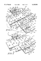
FIG. 1 is a perspective view of an unassembled three-piece container in accordance with a first embodiment of the present invention showing a body and detached left-side and right-side end panels that can be assembled to form the container shown in FIG. 7;
FIG. 2 is a view similar to FIG. 1 showing the left-side and right-side end panels coupled to outer surfaces of left and right end flaps included in the body at an initial stage of container assembly;
FIG. 3 is a view similar to FIG. 2 showing partial folding of a left-side end panel around two end panel support flaps included in the body and showing inward pivoting movement of two more end panel support flaps included in the body toward right-side end panel-supporting positions before the right-side end panel is folded to assume the "wrapped" position shown in FIGS. 6-10;
FIG. 4 is a view similar to FIG. 3 showing formation of the left-side end panel to define a pocket receiving two end panel support flaps and showing upright stacking tabs protruding from an aperture formed in the left-side end panel;
FIG. 5 is a view similar to FIG. 4 showing partial folding of the right-side end panel;
FIG. 6 is a view similar to FIG. 5 after folding of the right-side end panel and before moving first and second lid sections to assumed closed positions;
FIG. 7 is a view similar to FIG. 6 of a closed container in accordance with the first embodiment of the present invention;
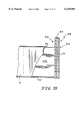
FIG. 8 is an end elevation view of the right end of the container of FIG. 7 with portions broken away;
FIG. 9 is a sectional view taken along line 9--9 of FIG. 8;
FIG. 10 is a sectional view taken along line 10--10 of FIG. 9;
FIG. 11 is a perspective view of an unassembled three-piece container used in accordance with a second embodiment of the present invention that can be assembled to form the container shown in FIG. 14;
FIG. 12 is a view similar to FIG. 11 showing left-side and right-side end panels coupled to inner surfaces of left and right end flaps included in the body at an initial stage of container assembly;
FIG. 13 is a view similar to FIG. 12 during partial assembly of the container;
FIG. 14 is a view similar to FIG. 13 following assembly of the container and closure of two lid sections included in the container;
FIG. 15 is an end elevation view of the right end of the container of FIG. 14 with portions broken away;
FIG. 16 is a sectional view taken along line 16--16 of FIG. 15;
FIG. 17 is a sectional view taken along line 17--17 of FIG. 15;
FIG. 18 is a perspective view of an unassembled three-piece container used in accordance with a third embodiment of the present invention showing a body and detached left-side and right-side end panels that can be assembled to form the container shown in FIG. 22 and showing two sets of tabs on each of the left-side and right-side end panel;
FIG. 19 is a view similar to FIG. 18 showing the tabbed left-side and right-side end panels coupled to left and right end flaps at an initial stage of container assembly;
FIG. 20 is a view similar to FIG. 19 showing folding and placement of the tabs on the left-side and right-side end panels during an early stage of container assembly;
FIG. 21 is a view similar to FIG. 20 showing folding and placement of the tabs on the left-side and right-side end panels during a later stage of container assembly;
FIG. 22 is a view similar to FIG. 21 following assembly of the container and closure of two lid sections included in the container, with portions broken away, showing placement of two tabs in a pocket formed in the left end panel;
FIG. 23 is an end elevation view of the right end of the container of FIG. 22 with portions broken away;
FIG. 24 is a sectional view taken along line 24--24 of FIG. 23;
FIG. 25 is a sectional view taken along line 25--25 of FIG. 23;
FIG. 26 is a perspective view of a three-piece container in accordance with a fourth embodiment of the present invention, with portions broken away, showing one of the tabs included in a left-side end panel positioned to engage a rear side wall (rather than positioned to lie in a pocket formed in the left-side end panel as shown, for example, in FIG. 22);
FIG. 27 is a perspective view of the container of FIG. 26 showing folding and placement of the tabs on the left-side and right-side panels during an early stage of container assembly;
FIG. 28 is a view similar to FIG. 27 showing folding and placement of the tabs on the left-side and right-side end panels during a later stage of container assembly;
FIG. 29 is an end elevation view of the right end of the container of FIG. 26 with portions broken away;
FIG. 30 is a sectional view taken along line 30--30 of FIG. 29;
FIG. 31 is a sectional view taken along line 31--31 of FIG. 29;
FIG. 32 is a diagrammatic plan view of a rotating conveyor for facilitating assembly of left-side and right-side end panels to bodies in accordance with the present invention;
FIG. 33 is a perspective view of a jig provided on the rotating conveyor of FIG. 32;
FIG. 34 is a perspective view of a partly assembled three-piece container in accordance with a fifth embodiment of the present invention showing a body including a left end flap, a pair of side wall support flaps appended to the left end flap, a right end flap, and a pair of side wall support flaps appended to the right end flap, a foldable left-side end panel coupled to the left end flap, and a foldable right-side end panel coupled to the right end flap;
FIG. 35 is a view similar to FIG. 34 showing folding and placement of the side wall support flaps and the end panels during an early stage of container assembly;
FIG. 36 is a view similar to FIG. 35 showing final placement of the folded left-side and right-side end panels, formation of a rear side wall and auxiliary rear side wall to define a pocket receiving two of the side wall support flaps, and inward pivoting movement of two more side wall support flaps toward positions for supporting a front side wall and an auxiliary front side wall;
FIG. 37 is a view similar to FIG. 36 showing a fully assembled container and showing formation of the front side wall and auxiliary front side wall to define a pocket receiving the side wall support flaps.
FIG. 38 is a sectional view taken along line 38--38 of FIG. 37; and
FIG. 39 is a sectional view taken along line 30--30 of FIG. 38.
A blank 10 for use in making a paperboard container is shown in FIG. 1. Blank 10 can be manufactured and folded as shown in FIGS. 2-5 to form a container 12 shown in FIGS. 6 and 7. Container 12 is configured to hold various goods such as fruits, vegetables, and other agricultural products (not shown).
Each of panels 14, 16, 18 is die cut or otherwise formed to have the configuration shown in FIG. 1. It is within the scope of the present invention to vary the size and shape of panels 14, 16, 18 to produce either a rectangular, square, or other shape container 12 of any suitable length, width, and height dimension. Although end panels 16, 18 are made of two-ply construction (e.g., two layers of corrugated material) as shown in FIG. 1, it is within the scope of the present invention to make end panels 16, 18 of single-ply construction or any suitable multi-ply construction.
Each of first and second left end panel support flaps 42 and 62 of body panel 14 is formed to include a cantilevered inner stacking tab 82, as shown in FIG. 1. One inner stacking tab 82 is appended to edge 43 of first left end panel support flap 42 and configured to include a lid-receiving slot 84 therein. The other inner stacking tab 82 is appended to edge 63 of second left end panel support flap 62 and configured to include a lid-receiving slot 86 therein.
Each of first and second right end panel support flaps 46, 66 of body panel 14 is formed to include a cantilevered inner stacking tab 88 as shown in FIG. 1. One inner stacking tab 88 is appended to edge 47 of first right end panel support wall 46 and configured to include a lid-receiving slot 90 therein. The other inner stacking tab 88 is appended to edge 67 of second right end panel support flap 66 and configured to include a lid-receiving slot 92 therein.
Each of left-side and right- side end panels 16, 18 includes an outer panel section 110, an inner panel section 112, and a top edge section 114 interconnecting outer and inner panel sections 110, 112 as shown in FIG. 1. Top edge section 114 can have a length and width as shown or be established by material along a single fold line (not shown).
Each outer panel section 110 is formed to include cutouts 115 which cooperate and align with stacking tab-receiving apertures 40 to form openings 41 for receiving stacking tabs therein when outer panel section 110 of left-side end panel 16 is attached to an inner wall of left end flap 22 and outer panel section 110 of right-side end panel 18 is attached to an inner wall of right end flap 26 as shown, for example, in FIG. 2. Each inner panel section 112 and appendant top edge section 114 is formed to include elongated cutout 116 defining an opening (shown in FIG. 1) receiving two outer stacking tabs 118 appended to outer panel section 110. The two outer stacking tabs 118 are aligned to "face" one another in spaced-apart relation and define lid-receiving slots 120, 122 therein as shown in FIG. 1. An outer edge 124 of each of inner panel sections 112 is formed to include a finger slot 126 flanked on either side by a friction tab 128 for snugly engaging against floor 20 when the end panels 16, 18 are fully assembled as shown, for example, in FIGS. 4, 8, and 9.
In a presently preferred embodiment shown in FIGS. 1 and 8-10, each of left-side and right- side end panels 16, 18 is made of two layers of corrugated material as shown. This provides sturdy end panels 16, 18 so as to rigidity outer stacking tabs 18.
During manufacturing, a single blank 10 is made by gluing two end panels 16, 18 to a body panel 14. Single blanks 10 can then be shipped flat easily to destinations throughout the world and to destinations in agricultural fields. These blanks 10 can also be assembled manually or mechanically at container-assembly facilities.
Once flat blanks 10 arrive at a point of use in the field, blanks 10 can be assembled or knocked down easily by hand. The design of blanks 10 allow an end user to "hand assemble" the corrugated container 12 without the use of any machinery. As noted previously, for agricultural uses, this allows container 12 to be assembled easily in the field and for industrial uses this allows container 12 to be "collapsed" easily for either disposal or "reuse." Such a design for blank 10 eliminates the need for an end user to purchase special mechanical equipment for use in erecting or knocking down container 12. Containers 12 are adapted to be made by hand on a conveyor provided with a jig as shown, for example, in FIGS. 32 and 33. Containers 12 can also be made using fully automated container-assembling machinery at a central packing station or elsewhere.
A presently preferred embodiment of container 12 is shown in FIGS. 5-12. As shown, for example, in FIG. 7, once assembled, inner stacking tabs 82 and double-thickness outer stacking tabs 118 are aligned adjacent to one another to form two sturdy and rigidified stacking tab sets along left-side end panel 16. Likewise, inner stacking tabs 88 and another set of outer stacking tabs 118 are aligned and cooperate along right-side end panel 18 to form opposite sets of sturdy and rigidified stacking tabs. When containers 12 are stacked on top of one another, the four upstanding sets of stacking tabs shown in FIG. 7 will engage the four stacking tab-receiving openings 41 that are formed along the underside of floor 20, two of which are shown, for example, in FIGS. 7-9.
Assembly of blank 10 is shown in sequence in FIGS. 2-6. First, blank 20 comprising body panel 14 and pre-glued left-side and right- side end panels 16 and 18 is laid out flat on the ground or assembly table as shown in FIG. 2. The inner panel section of 112 is folded as shown in FIG. 3 to "wrap" around the first and second left end panel support flaps 42, 62 in folding direction 91 to pass inner stacking tabs 82 on support flaps 42, 62 through cutout 116 so that left-side end panel 16 is movable to the position shown in FIG. 4 to "sandwich" or "trap" body panel left end flap 22 between the outer and inner panel sections 110, 112 of left-side end panel 16. Right-side end panel 18 is folded in the same way as shown also in FIGS. 5 and 6. Outer stacking tabs 118 on left-side end panel 16 and outer stacking tabs 118 on right-side end panel 18 are now exposed and aligned with inner stacking tabs 82 as shown in FIGS. 6 and 7. It is within the scope of the present invention to fully or partly preform left-side end panel 16 and then place the preformed end panel 16 down onto and over end panel support flaps 42, 62 and couple end panel 16 to body panel 14 and use the same installation technique for right-side end panel 18.
A second embodiment of a container in accordance with the present invention is shown in FIGS. 11-17. In this embodiment, left-side end panel 16 is coupled to an inner surface 95 of left end flap 22 (instead of outer surface 94 as shown in FIGS. 1 and 2) and right-side end panel 18 is coupled to an inner surface 95 of right-end flap 26 (instead of outer surface 94 as shown in FIGS. 1 and 2). Such coupling to inner surfaces 95 is illustrated in FIGS. 11 and 12. In all other respects, the descriptions and accounts of the first embodiment of FIGS. 1-10 apply to this second embodiment.
A third embodiment of a container in accordance with the present invention is shown in FIGS. 18-25 and a fourth embodiment of a container in accordance with the present invention is shown in FIGS. 26-31. In these embodiments, tabbed left-side and right- side end panels 216 and 218 are coupled to body panel 14. Two of the four tabs on each of the left- side end panels 216 and 218 are folded "inwardly" to rigidity the container end walls in the third embodiment as shown, for example, in FIGS. 20-22 and are folded "outwardly" to rigidity the container side wars in the fourth embodiment as shown, for example, in FIGS. 26-28.
Left-side end panel 216 and right-side end 218 are coupled to body panel 14 to produce a blank 210 that can be assembled to produce container 312 shown in FIG. 22 or container 412 shown in FIG. 26. Left-side end panel 16 shown in FIG. 1 is modified to include two tabs 201 appended to opposite ends of outer panel section 110 and two tabs 203 appended to opposite ends of inner panel section 112 as shown, for example, in FIG. 18 to produce left-side end panel 216. Right-side end panel 18 shown in FIG. 1 is modified in a similar way to produce right-side end panel 218. Although end panels 216, 218 are made of a single layer of corrugated material, it is within the scope of the present invention to make portions of end panels 216, 218 of multiple layers of corrugated or other suitable paperboard material.
Left-side end panel 216 is coupled to left end flap 22 as shown, for example, in FIGS. 18 and 19 to position one of tabs 201 adjacent to end panel support flap 42 and another of tabs 201 adjacent to end panel support flap 62. Likewise, right-side end panel 218 is coupled to right end flap 26 as shown, for example, in FIGS. 18 and 19 to position one of tabs 203 adjacent to end panel support flap 46 and another of tabs 201 adjacent to end panel support flap 66 to produce a blank 210 for use in accordance with the third and fourth embodiments of the present invention and shown, for example, in FIG. 19.
Referring now to FIGS. 20-22 and 23-25, it will be seen that tabs 201 and 203 are folded during container assembly so that when the end panels 216, 218 are folded as shown in FIGS. 20-122, the tabs 201 on left-side end panel 216 are positioned to lie between outer panel section 110 and the two left-side end panel support flaps 42 and 62 while tabs 201 on right-side end panel 218 are positioned to lie between outer panel section 110 and the two right-side end panel support flaps 46 and 66. In this third embodiment, tabs 203 are folded or tucked "inwardly" in directions 203a and 203b (see FIG. 20) so that when the end panels 216, 218 are folded as shown in FIGS. 20-22, the tabs 203 on left-side end panel 216 are positioned to lie between the two left-side end panel support flaps 42 and 62 and inner panel section 112 while tabs 203 on right-side end panel 218 are positioned to lie between the two right-side end panel support flaps 46 and 66 and inner panel section 112.
In the fourth embodiment shown in FIGS. 26-31, tabs 203 are folded "outwardly" in directions 203c and 203d (see FIG. 27) so that when end panels 216, 218 are folded as shown in FIGS. 27, 28, and 26, one tab 203 on each of left-side and right-side end panels 216 is positioned to engage and be coupled to front side wall 30 and the other tab 203 on each of left-side and right-side end panels 218 is positioned to engage and be coupled to rear side wall 34. Glue or other suitable means can be used to accomplish such coupling.
A process and apparatus for assembling multi-piece containers is disclosed herein. A conveyor and a series of container-assembly jigs on the conveyor is used to facilitate assembly of multi-piece container such as, for example, a container comprising a body panel and left-side and right-side end panels.
One embodiment of a container-assembly apparatus in accordance with the present invention is shown in FIGS. 32 and 33. Apparatus 420 includes a turntable 422 supported for rotation on a support post 424. In the illustrated embodiment, turntable 422 has an octagon shape and four container-assembly jigs 426. Each jig 426 comprises four jig pegs 428 coupled to turntable 422 as shown in FIG. 33. Jig pegs 428 are arranged to lie in, for example, a rectangular pattern, and to extend into four of apertures 37 formed in body panel 14 and into two of apertures 39 formed in each of left-side and right- side end panels 16, 18 as shown in FIG. 3 during assembly of panels 14, 16, and 18 to produce containers. It is within the scope of the present invention to vary the number, size, shape, and arrangement of jig pegs 428 on turntable 422 and to vary the number and location of jig peg-receiving apertures formed in panels 14, 16, 18 or other panels or pieces assembled to form containers. It is also within the scope of the present invention to provide a series of jigs 426 on a movable conveyor belt or the like instead of on a rotating turntable 422.
Four work stations are provided for workers using turntable 422 to assemble containers. At first work station 430, a first worker 431 takes a body panel 14 from a stack of panels 14 and places it on a first jig 426 so that jig pegs 428 fit into locator hole 37 to position the panel 14 properly in a predetermined position on turntable 422. At second work station 432, a second worker 433 applies glue 429 to each end flap 22, 26 included in body panel 14. At third work station 434, a third worker 435 removes two end panels from a stack of end panels and couples one of the panels to the glue-carrying left end flap 22 to produce left-side end panel 16 and couples the other panel to the glue-carrying right end flap 26 to produce right-side end panel 18. At fourth work station 436, a fourth worker 437 removes a completed blank 10 from turntable 422 and places it in a stack of blanks 10 located to one side of apparatus 430. During this process, turntable 422 is rotated manually or automatically in direction 438 to enable the workers to perform their assignments simultaneously. By rotating turntable 422 about support post 424 at a rate of 12-15 revolutions per minute, about 750 containers could be assembled during each fifty-minute period or about 6,000 assembled containers per four-worker shift.
A fifth embodiment of a container in accordance with the present invention is shown in FIGS. 34-39. In this embodiment, support flaps are appended to left and right end panels 22, 26 as shown in FIG. 34 (instead of being appended to front and rear side walls as shown in connection with other embodiments) and moved to provide support for front and rear side walls as shown in FIGS. 35 and 36 (instead of being moved to provide support for left-side and right-side end panels as shown in connection with other embodiments).
As shown in FIG. 34, body panel 514 includes floor 20, left and right end flaps 22, 26, front and rear side walls 30, 34, an auxiliary front side wall 31 appended to front side wall 30, and an auxiliary rear side wall 35 appended to rear side wall 34. Each of left-side and right- side end panels 516, 518 includes an outer panel section 510, an inner panel section 512, and a top edge section 514 interconnecting sections 510 and 512. Panels 516, 518 can be made of one or more layers of corrugated material or other suitable paperboard material.
First and second side wall support flaps 542 and 562 are appended to opposite ends of left end flap 22 and third and fourth side wall support flaps 546 and 566 are appended to opposite ends of right end flap 26 as shown, for example, in FIG. 34. A friction tab 528 is appended to inner panel section of each of left-side and right- side end panels 516, 518 as shown in FIG. 34.
Assembly of a container using a blank 510 of the type illustrated in FIG. 34 is shown in FIGS. 35-37. Left-side and right- side end panels 516, 518 are folded as shown in FIG. 35 to position side wall support flaps 542, 546 along fold line 52 and to position side wall support flaps 562, 566 along fold line 36. Then rear side walls 34, 35 and front side walls 30, 31 are moved as shown in FIG. 36 to produce container 512 shown in FIG. 37. In container 512, side wall support flaps 542, 546 lie in a pocket defined by front side walls 530, 531 and side wall support flaps 562, 566 lie in a pocket defined by rear side walls 534, 535 as shown, for example, in FIGS. 37-39.
The subject matter disclosed in co-pending U.S. Provisional Patent Application No. 60/058,339 is incorporated by reference herein. The filing date of that application was Sep. 10, 1997.
Although the invention has been described in detail with reference to certain preferred embodiments, variations and modifications exist within the scope and spirit of the invention as described and defined in the following claims.
Claims (66)
1. A container comprising
a body including a floor having two sides and two ends, a front side wall appended to the floor along one side of the floor, a rear side wall appended to the floor along a second side of the floor to lie opposite the front side wall, first and second end panel support flaps appended to the front side wall, third and fourth end panel support flaps appended to the rear side wall, right and left end flaps appended to the floor at each end respectively, and first and second tab receiving apertures extending through the floor adjacent the points of appending of the first and second end panel support flaps respectively,
a left-side end panel separately formed from a material unconnected to the body and positioned to lie at one end of the floor between the front and rear side walls and formed to include a left-side pocket receiving the first and third end panel support flaps therein and having at least one stacking tab insertable into the first tab receiving aperture, and
a right-side end panel separately formed from a material unconnected to the body and positioned to lie at an opposite end of the floor between the front and rear side walls and formed to include a right-side pocket receiving the second and fourth end panel support flaps therein and having at least one tab insertable into the second aperture.
2. The container of claim 1, wherein the left end flap appended to the floor is positioned to lie between the front and rear side walls and, the left-side end panel is coupled to the left end flap.
3. The container of claim 2, wherein the left-side end panel includes an outer panel section, an inner panel section, and a top edge section interconnecting the outer and inner panel sections and cooperating with the outer and inner panel sections to define the left-side pocket therebetween, and tie outer panel section is coupled to the outer surface of the left end flap.
4. The container of claim 2, wherein right end flap appended to the floor is positioned to lie between the front and rear side walls and opposite the left end flap and the right-side end panel is coupled to the right end flap.
5. The container of claim 4, wherein the front and rear side walls cooperate to define an interior region of the body, each of the left and right end flaps include an inner surface facing into the interior region and an outer surface facing away from the interior region, the left-side end panel is coupled to the outer surface of the left end flap, and the right-side end panel is coupled to the outer surface of the right end flap.
6. The container of claim 5, wherein each of the left-side and right-side end panels include an outer panel section, an inner panel section, and a top edge section interconnecting the outer and inner panel sections and cooperating with the outer and inner panel sections to define one of the left-side and right-side pockets therebetween, the outer panel section of the left-side end panel is coupled to the outer surface of the left end flap and the outer panel section of the right-side end panel is coupled to the outer surface of the right end flap.
7. The container of claim 1, wherein the left-side end panel includes an outer panel section, an inner panel section, and a top edge section interconnecting the outer and inner panel sections and cooperating with the outer and inner panel sections to define the left-side pocket therebetween.
8. The container of claim 7, wherein the inner panel section includes an edge frictionally engaging the floor.
9. The container of claim 7, wherein the outer panel section includes at least one outer stacking tab extending above the top edge section and away from the floor.
10. The container of claim 9, wherein the tab-receiving apertures also extends through the end panel support flaps and at least one of the first and third end panel support flaps includes an inner stacking tab extending through the tab-receiving aperture formed in the left-side end panel and mating with the at least one outer stacking tab included in the outer panel section.
11. The container of claim 7, wherein the right-side end panel includes an outer panel section, an inner panel section, and a top edge section interconnecting the outer and inner panel sections and cooperating with the outer and inner panel sections to define the right-side pocket therebetween.
12. The container of claim 11, wherein the inner panel section of each of the left-side and right-side end panels includes an edge frictionally engaging the floor.
13. The container of claim 11, wherein the outer panel section of each of the left-side and right-side end panels includes at least one outer stacking tab extending away from the floor.
14. The container of claim 1, wherein the left-side end panel is formed to include first and second outer stacking tabs and a stacking tab-receiving aperture adjacent to the first and second outer stacking tabs, the first end panel support flap includes an inner stacking tab extending through the stacking tab-receiving aperture and aligning with the first outer stacking tab, and the second end panel support flap includes an inner stacking tab extending through the stacking tab-receiving aperture and aligning with the second outer stacking tab.
15. The container of claim 14, wherein each of the inner stacking tabs is formed to include a lid-receiving slot, the body further includes a first lid section appended to the front side wall and a second lid section appended to the rear side wall, a portion of the first lid section fits into the lid-receiving slot formed in one of the inner stacking tabs, and a portion of the second lid section fits into the lid-receiving slot formed in another of the inner stacking tabs.
16. The container of claim 14, wherein the left-side end panel includes a border edge defining the stacking tab-receiving aperture, the inner stacking tab of the first end panel support flap is positioned to lie adjacent to a portion of the border edge, and the inner stacking tab of the third end panel support flap is positioned to lie adjacent to another portion of the border edge.
17. The container of claim 16, wherein each inner stacking tab and each of the first and second outer stacking tabs is formed to include a lid-receiving slot and the body further includes a first lid section appended to the front side wall and engaged in the lid-receiving slots of the first outer stacking tab and the inner stacking tab of the first panel support wall and a second lid section appended to the rear side wall and engaged in the lid-receiving slots of the second outer stacking tab and the inner stacking tab of the second panel support wall.
18. The container of claim 14, wherein the first tab-receiving aperture is configured to receive stacking tabs included in an underlying container.
19. The container of claim 1, wherein each of the first and third end panel support flaps is positioned to lie perpendicular to the front side wall and each of the second and fourth end panel support flaps is positioned to lie perpendicular to the rear side wall.
20. The container of claim 19, wherein the first and third end panel support flaps are aligned to lie in coplanar relation.
21. The container of claim 20, wherein the second and fourth end panel support flaps are aligned to lie in coplanar relation.
22. The container of claim 20, wherein the body further includes a left end flap appended to the floor and coupled to the left-side end panel and the left end flap is positioned to lie in parallel relation to the first and third end panel support flaps.
23. The container of claim 22, wherein the left end flap is positioned to lie between the outer-panel section of the left-side end panel and the first and third panel support walls.
24. The container of claim 23, wherein the outer panel section of the left-side end panel is coupled to the left end flap.
25. The container of claim 1, wherein the left-side end panel includes an outer panel section, an inner panel section, a top edge section interconnecting the outer and inner panel sections and cooperating with the outer and inner panel sections to define the left-side pocket therebetween, and a first pair of tabs appended to the inner panel section, and each tab in the first pair of tabs is coupled to one of the front and rear side walls.
26. The container of claim 25, wherein the inner panel section includes opposite ends and each tab in the first pair of tabs includes an edge appended to one of the opposite ends.
27. The container of claim 25, wherein the left-side end panel further includes a second pair of tabs appended to the outer panel section and each tab in the second pair of tabs is positioned to lie in a space between the outer panel section and one of the first and third end panel support flaps.
28. The container of claim 27, wherein the outer panel section includes opposite ends and each tab in the second pair of tabs includes an edge appended to one of the opposite ends of the outer panel section.
29. A container comprising
a body including opposite front and rear side walls, opposite left and right end flaps, a floor appended to each of the front side wall, rear side wall, left end flap, and right end flap, a first end panel support flap appended to the front side wall and arranged to extend toward the rear side wall alongside the left end flap, a second end panel support flap appended to the front side wall and arranged to extend toward the rear side wall alongside the right end flap, a third end panel support flap appended to the rear side wall and arranged to extend toward the front side wall alongside the left end flap, a fourth end panel support flap appended to the rear side wall and arranged to extend toward the front side wall alongside the right end flap, and tab receiving apertures extending through the floor adjacent the points of appending of the floor and panel support flaps,
a left-side end panel separately formed from a material unconnected to the body and coupled to the left end flap and positioned to lie between the front and rear side walls, the left-side end panel including an outer panel section and an inner panel section cooperating with the outer panel section of the left-side end panel to trap the first and third end panel support flaps therebetween, the inner panel section having at least one stacking tab insertable into one of the tab receiving apertures, and
a right-side end panel separately formed from a material unconnected to the body and coupled to the right end flap and positioned to lie between the front and rear side walls, the left-side end panel including an outer panel section and an inner panel section cooperating with the outer panel section of the right-side end panel to trap the second and fourth end panel support flaps therebetween, the inner panel section having at least one stacking tab insertable into one of the tab receiving apertures.
30. The container of claim 29, wherein each of the first and third end panel support flaps is positioned to lie perpendicular to the front side wall and each of the second and fourth end panel support flaps is positioned to lie perpendicular to the rear side wall.
31. The container of claim 30, wherein the first and third end panel support flaps are aligned to lie in coplanar relation.
32. The container of claim 31, wherein the second and fourth end panel support flaps are aligned to lie in coplanar relation.
33. The container of claim 30, wherein the left end flap is positioned to lie in spaced-apart parallel relation to the first and third end panel support flaps.
34. The container of claim 33, wherein the outer panel section of the left-side end panel is positioned to lie between the left end flap and the first and third end panel support flaps.
35. The container of claim 30, wherein the left end flap is positioned to lie in parallel relation to the first and third end panel support flaps and the right end flap is positioned to lie in parallel relation to the second and fourth end panel support flaps.
36. The container of claim 35, wherein the outer panel section of the left-side end panel is positioned to lie between the left end flap and the first and third end panel support flaps and the outer panel section of the right-side end panel is positioned to lie between the right end flap and the second and fourth end panel support flaps.
37. The container of claim 36, wherein the outer panel section of the left-side end panel is coupled to the left end flap and the outer panel section of the right-side end panel is coupled to the right end flap.
38. The container of claim 35, wherein the left end flap is positioned to lie between the outer panel section of the left-side end panel and the first and third panel support walls and the right end flap is positioned to lie between the outer panel section of the right-side end panel and the second and fourth panel support walls.
39. The container of claim 38, wherein the outer panel section of the left-side end panel is coupled to the left end flap and the outer panel section of the right-side end panel is coupled to the right end flap.
40. The container of claim 29, wherein the left-side end panel further includes a first pair of tabs appended to opposite ends of the inner panel section of the left-side end panel.
41. The container of claim 40, wherein each tab in the first pair of tabs is positioned to lie in a space between the inner panel section and one of the first and third end panel support flaps.
42. The container of claim 41, wherein the left-side end panel further includes a second pair of tabs appended to the outer panel section and each tab in the second pair of tabs is positioned to lie in a space between the outer panel section and one of the first and third end panel support flaps.
43. The container of claim 40, wherein each tab in the first pair of tabs is coupled to one of the front and rear side walls.
44. The container of claim 43, wherein the left-side end panel further includes a second pair of tabs appended to the outer panel section and each tab in the second pair of tabs is positioned to lie in a space between the outer panel section and one of the first and third end panel support flaps.
45. A container comprising
a body including a floor, a front side wall appended to the floor, a rear side wall appended to the floor to lie opposite the front side wall, a left end flap appended to the floor a first end panel support flap appended to the front side wall, and a second end panel support flap appended to the rear side wall,
an end panel separately formed from a material unconnected to the body and positioned to lie at one end of the floor between the front and rear side walls and formed to include a pocket receiving the left end flap and the first and second end panel support flaps therein, and
wherein the floor includes at least one aperture therein, which aperture receives a tab located on the end panel.
46. The container of claim 45, wherein the left end flap is positioned to lie between the front and rear side walls and the end panel is coupled to the end flap.
47. The container of claim 46, wherein the front and rear side walls cooperate to define an interior region of the body, the end flap includes an inner surface facing into the interior region and an outer surface facing away from the interior region, and the end panel is coupled to the outer surface of the end flap.
48. The container of claim 47, wherein the end panel includes an outer panel section, an inner panel section, and a top edge section interconnecting the outer and inner panel sections and cooperating with the outer and inner panel sections to define the pocket therebetween, and the outer panel section is coupled to the outer surface of the end flap.
49. The container of claim 45, wherein the end panel includes an outer panel section, an inner panel section, and a top edge section interconnecting the outer and inner panel sections and cooperating with the outer and inner panel sections to define the pocket therebetween.
50. The container of claim 49, wherein the inner panel section includes the tab which has an edge that frictionally engages an edge of the aperture.
51. The container of claim 49, wherein the outer panel section includes at least one outer stacking tab extending above the top edge section and away from the floor.
52. The container of claim 51, wherein the aperture also extends through the and at least one of the first and second end panel support flaps includes an inner stacking tab extending through the tab-receiving aperture formed in the end panel and mating with the at least one outer stacking tab included in the outer panel section.
53. The container of claim 45, wherein the first end panel support flap is positioned to lie perpendicular to the front side wall and the second end panel support flap is positioned to lie perpendicular to the rear side wall.
54. The container of claim 53, wherein the first and second end panel support flaps are aligned to lie in coplanar relation.
55. A container comprising
a body including a floor, a front side wall appended to the floor, a rear side wall appended to the floor to lie opposite the front side wall, first and second end panel support flaps appended to the front side wall, and third and fourth end panel support flaps appended to the rear side wall,
a left-side end panel separately formed from a material unconnected to the body and positioned to lie at one end of the floor between the front and rear side walls, the left-side end panel including an outer panel section, an inner panel section, and a top edge section interconnecting the outer and inner panel sections, the outer and inner panel sections cooperating to define a left-side pocket receiving the first and third end panel support flaps therein, and
a right-side end panel separately formed from a material unconnected to the body and positioned to lie at an opposite end of the floor between the front and rear side walls, the right-side end panel including an outer panel section, an inner panel section, and a top edge section interconnecting the outer and inner panel sections, the outer and inner panel sections cooperating to define a right-side pocket receiving the second and fourth end panel support flaps therein, and wherein the body further includes at least one aperture at one end thereof and a left end flap appended to the floor at the location of the aperture and positioned to lie between the front and rear side walls and the outer panel section of the left-side end panel is coupled to the left end flap and the inner panel section of the left-side end panel is provided with a tab that extends into the aperture.
56. The container of claim 55, wherein each of the first and third end panel support flaps is positioned to lie between the left end flap and the inner panel section of the left-side end panel.
57. The container of claim 55, wherein the body further includes a right end flap appended to the floor and positioned to lie between the front and rear side walls and opposite the left end flap and the outer panel section of the right-side end panel is coupled to the right end flap.
58. The container of claim 57, wherein each of the second and fourth end panels is positioned to lie between the right end flap and the inner panel section of the right-side end panel.
59. The container of claim 58, wherein each of the first and third end panel support flaps is positioned to lie between the left end flap and the inner panel section of the left-side end panel.
60. The container of claim 57, wherein the front and rear side walls cooperate to define an interior region of the body, each of the left and right end flaps include an inner surface facing into the interior region and an outer surface facing away from the interior region, the outer panel section of the left-side end panel is coupled to the outer surface of the left end flap, and the outer panel section of the right-side end panel is coupled to the outer surface of the right end flap.
61. The container of claim 60, wherein each of the first and third end panel support flaps is positioned to lie between the outer surface of the inner panel section of the left-side end panel and the left end flap and each of the second and fourth end panel support flaps is positioned to lie between the outer surface of the inner panel section of the right-side end panel and the right end flap.
62. The container of claim 55, wherein each of the first and third end panel support flaps is positioned to lie perpendicular to the front side wall and between the left end flap and the inner panel section of the left-side end panel and each of the second and fourth end panel support flaps is positioned to lie perpendicular to the rear side wall and between the right end flap and the inner panel section of the right-side end panel.
63. The container of claim 62, wherein the first and third end panel support flaps are aligned to lie in coplanar relation and the second and fourth end panel support flaps are aligned to lie in coplanar relation.
64. The container of claim 55, wherein the inner panel section of each of the left-side and right-side end panels includes an edge frictionally engaging the floor.
65. The container of claim 55, wherein the outer panel section of each of the left-side and right-side end panels includes at least one outer stacking tab extending above the top edge section and away from the floor.
66. The container of claim 65, wherein the left-side end panel is formed to include a tab-receiving aperture adjacent to the at least one outer stacking tab and at least one of the first and third end panel support flaps includes an inner stacking tab extending through the tab-receiving aperture formed in the left-side end panel and mating with the at least one outer stacking tab included in the outer panel section of the left-side end panel.
Priority Applications (2)
| Application Number | Priority Date | Filing Date | Title |
|---|---|---|---|
| US08/964,936 US6138904A (en) | 1997-09-10 | 1997-11-05 | Three-piece container |
| BR9706472-6A BR9706472A (en) | 1997-09-10 | 1997-12-26 | Three-piece packaging |
Applications Claiming Priority (2)
| Application Number | Priority Date | Filing Date | Title |
|---|---|---|---|
| US5833997P | 1997-09-10 | 1997-09-10 | |
| US08/964,936 US6138904A (en) | 1997-09-10 | 1997-11-05 | Three-piece container |
Publications (1)
| Publication Number | Publication Date |
|---|---|
| US6138904A true US6138904A (en) | 2000-10-31 |
Family
ID=26737516
Family Applications (1)
| Application Number | Title | Priority Date | Filing Date |
|---|---|---|---|
| US08/964,936 Expired - Fee Related US6138904A (en) | 1997-09-10 | 1997-11-05 | Three-piece container |
Country Status (2)
| Country | Link |
|---|---|
| US (1) | US6138904A (en) |
| BR (1) | BR9706472A (en) |
Cited By (32)
| Publication number | Priority date | Publication date | Assignee | Title |
|---|---|---|---|---|
| US6443358B1 (en) * | 2001-08-14 | 2002-09-03 | Fruit Growers Supply Company | Stackable container |
| US20030111523A1 (en) * | 2000-07-24 | 2003-06-19 | Olav Haugan | Case |
| US20030160093A1 (en) * | 2002-02-28 | 2003-08-28 | Smith Steven H. | Reinforcement device for boxes and the like |
| US6641032B1 (en) | 2002-05-08 | 2003-11-04 | Fruit Growers Supply Company | Stackable container with reinforced corner |
| FR2841217A1 (en) * | 2002-06-24 | 2003-12-26 | Smurfit Socar Sa | Cardboard packaging comprises two internal and two external hinged flaps, external flaps comprising part hinged on itself and projecting tongues from internal flap walls engaged between external flaps and their hinged parts |
| EP1500597A1 (en) * | 2003-07-25 | 2005-01-26 | Société Anonyme dite SMURFIT-SOCAR | Package out of semi-rigid material having reclosable lid flaps |
| US20050061863A1 (en) * | 2002-02-15 | 2005-03-24 | International Paper Company | Paperboard container with bottom support |
| DE102005001631A1 (en) * | 2005-01-12 | 2006-07-20 | Tesa Ag | Folded carton for transporting objects, animals has 3-part cut-out with base section with floor, 2 opposing side parts, 2 separate lateral sub-sections with hinged edges, pivoting flaps with tongues for insertion into slots in base section |
| US20060169756A1 (en) * | 2005-01-28 | 2006-08-03 | Maxco Supply, Inc. | Convertible box |
| FR2882032A1 (en) * | 2005-02-17 | 2006-08-18 | Vg Goossens Sa Sa | Cardboard case for packing fragile product, has reinforcing plates made of micro-corrugated cardboard, where orientation of microcorrugation of plates is chosen to be perpendicular to base of body and cover |
| ES2275390A1 (en) * | 2005-02-07 | 2007-06-01 | Gracian Mateo Peralta | Cardboard container for containing different products e.g. fruits, vegetables has retention complemented with portions of extensions and provided in minor sidewalls |
| US20070194095A1 (en) * | 2006-02-22 | 2007-08-23 | Smurfit-Stone Container Enterprises, Inc. | Container having reclosable end wall |
| US20080155944A1 (en) * | 2007-01-03 | 2008-07-03 | Krooom Ltd. | Base sheet of corrugated cardboard or other stiff sheet material for use in forming various three-dimensional articles, and kit including same |
| US20090286663A1 (en) * | 2008-05-15 | 2009-11-19 | York Container Company | Materials for and method for manufacturing container with corner supports and resulting container |
| US20090321506A1 (en) * | 2008-06-30 | 2009-12-31 | Rand Whitney Group, LLC | Structures for securing containers |
| US20100083618A1 (en) * | 2008-10-08 | 2010-04-08 | York Container Company | Materials for and method for manufacturing container with stacking shoulders and resulting container |
| US20100120594A1 (en) * | 2008-11-11 | 2010-05-13 | York Container Company | Materials for and method for manufacturing container with end supports and resulting container |
| US20100234201A1 (en) * | 2008-05-15 | 2010-09-16 | York Container Company | Materials for and method for manufacturing a container with corner supports and the resulting container |
| US20100247272A1 (en) * | 2009-03-27 | 2010-09-30 | York Container Company | Materials for and method for manufacturing retail container and resulting retail container |
| US20120240463A1 (en) * | 2009-10-29 | 2012-09-27 | Soprema | Modular planting and cultivating container and system and revegetation method using such containers |
| US9527622B2 (en) | 2015-05-29 | 2016-12-27 | Inteplast Group Ltd. | Reusable produce containers and related methods |
| CN107499722A (en) * | 2017-09-15 | 2017-12-22 | 东莞职业技术学院 | A kind of corrugated case for being applied to transport pears |
| CN107618720A (en) * | 2017-09-15 | 2018-01-23 | 东莞职业技术学院 | A kind of corrugated case for being applied to transport pawpaw |
| USD812468S1 (en) | 2016-07-01 | 2018-03-13 | Inteplast Group Corporation | Foldable container |
| CN108248988A (en) * | 2018-01-18 | 2018-07-06 | 深圳创维-Rgb电子有限公司 | A kind of Packaging Box |
| US10220975B2 (en) | 2016-05-31 | 2019-03-05 | Inteplast Group Corporation | Column and cross stacking containers and related methods |
| US10351291B2 (en) | 2015-05-29 | 2019-07-16 | Inteplast Group Corporation | Reusable produce containers and related methods |
| US10611513B2 (en) | 2014-01-29 | 2020-04-07 | General Mills, Inc. | Paperboard carton |
| US10633141B2 (en) | 2015-07-24 | 2020-04-28 | General Mills, Inc. | Paperboard carton |
| US10683129B2 (en) | 2016-02-17 | 2020-06-16 | General Mills, Inc. | Paperboard carton |
| US11161644B2 (en) * | 2019-06-19 | 2021-11-02 | Geoffrey Alan Moss | Modular stackable merchandise trays |
| US20220315297A1 (en) * | 2021-04-06 | 2022-10-06 | Fameccanica.Data S.P.A. | Child-proof paper or cardboard container |
Citations (23)
| Publication number | Priority date | Publication date | Assignee | Title |
|---|---|---|---|---|
| US2401742A (en) * | 1945-02-05 | 1946-06-11 | Baltimore Paper Box Co | Carton |
| US2409673A (en) * | 1945-01-12 | 1946-10-22 | Downing Box Company | Fiberboard container having reinforced ends and integral hinged closure |
| US2483174A (en) * | 1947-05-06 | 1949-09-27 | Belsinger Inc | Sealable carton with multiply bottom |
| US2682362A (en) * | 1951-02-06 | 1954-06-29 | Convoy Inc | Tote box |
| US2727675A (en) * | 1951-11-09 | 1955-12-20 | Waldorf Paper Prod Co | Shipping container |
| US2965279A (en) * | 1958-04-18 | 1960-12-20 | Continental Can Co | Tray |
| US3008625A (en) * | 1959-03-18 | 1961-11-14 | William T Cook | Fruit shipping container |
| US3157346A (en) * | 1962-06-26 | 1964-11-17 | American Box Corp Of Californi | Stacking paperboard lug box |
| US3184139A (en) * | 1962-12-03 | 1965-05-18 | Conescu Sidney | Box construction |
| US4134533A (en) * | 1977-12-19 | 1979-01-16 | Container Corporation Of America | Stackable container |
| US4257550A (en) * | 1979-08-24 | 1981-03-24 | Liberty Carton Company | Pilfer-proof container |
| US4291830A (en) * | 1979-12-26 | 1981-09-29 | Georgia-Pacific Corporation | Container with locking lid |
| US4304351A (en) * | 1980-07-03 | 1981-12-08 | Crown Zellerbach Corporation | Container with cover lock |
| US4347968A (en) * | 1976-12-27 | 1982-09-07 | Champion International Corporation | Stackable carton for perishable commodities |
| US4389013A (en) * | 1981-08-26 | 1983-06-21 | Georgia-Pacific Corporation | Container having a self-locking lid |
| US4497408A (en) * | 1982-11-29 | 1985-02-05 | Willamette Industries, Inc. | Stackable container with locking lid |
| US4770339A (en) * | 1987-05-06 | 1988-09-13 | International Paper Company | Ventilated, stackable grape box |
| US4884739A (en) * | 1986-01-29 | 1989-12-05 | Packaging Corporation Of America | Container for produce and the like |
| US4911355A (en) * | 1989-06-19 | 1990-03-27 | James Bannister | Foldable carton |
| US5263636A (en) * | 1993-03-25 | 1993-11-23 | Aure David A | Produce carton strenghening bracket and produce carton |
| US5335844A (en) * | 1992-08-19 | 1994-08-09 | Young Thomas R | Fruit and produce container |
| US5361974A (en) * | 1993-05-27 | 1994-11-08 | Anderson & Middleton Company | Box construction |
| US5458283A (en) * | 1995-04-24 | 1995-10-17 | Packaging Corporation Of America | Stackable container for storing fresh produce |
-
1997
- 1997-11-05 US US08/964,936 patent/US6138904A/en not_active Expired - Fee Related
- 1997-12-26 BR BR9706472-6A patent/BR9706472A/en not_active Application Discontinuation
Patent Citations (23)
| Publication number | Priority date | Publication date | Assignee | Title |
|---|---|---|---|---|
| US2409673A (en) * | 1945-01-12 | 1946-10-22 | Downing Box Company | Fiberboard container having reinforced ends and integral hinged closure |
| US2401742A (en) * | 1945-02-05 | 1946-06-11 | Baltimore Paper Box Co | Carton |
| US2483174A (en) * | 1947-05-06 | 1949-09-27 | Belsinger Inc | Sealable carton with multiply bottom |
| US2682362A (en) * | 1951-02-06 | 1954-06-29 | Convoy Inc | Tote box |
| US2727675A (en) * | 1951-11-09 | 1955-12-20 | Waldorf Paper Prod Co | Shipping container |
| US2965279A (en) * | 1958-04-18 | 1960-12-20 | Continental Can Co | Tray |
| US3008625A (en) * | 1959-03-18 | 1961-11-14 | William T Cook | Fruit shipping container |
| US3157346A (en) * | 1962-06-26 | 1964-11-17 | American Box Corp Of Californi | Stacking paperboard lug box |
| US3184139A (en) * | 1962-12-03 | 1965-05-18 | Conescu Sidney | Box construction |
| US4347968A (en) * | 1976-12-27 | 1982-09-07 | Champion International Corporation | Stackable carton for perishable commodities |
| US4134533A (en) * | 1977-12-19 | 1979-01-16 | Container Corporation Of America | Stackable container |
| US4257550A (en) * | 1979-08-24 | 1981-03-24 | Liberty Carton Company | Pilfer-proof container |
| US4291830A (en) * | 1979-12-26 | 1981-09-29 | Georgia-Pacific Corporation | Container with locking lid |
| US4304351A (en) * | 1980-07-03 | 1981-12-08 | Crown Zellerbach Corporation | Container with cover lock |
| US4389013A (en) * | 1981-08-26 | 1983-06-21 | Georgia-Pacific Corporation | Container having a self-locking lid |
| US4497408A (en) * | 1982-11-29 | 1985-02-05 | Willamette Industries, Inc. | Stackable container with locking lid |
| US4884739A (en) * | 1986-01-29 | 1989-12-05 | Packaging Corporation Of America | Container for produce and the like |
| US4770339A (en) * | 1987-05-06 | 1988-09-13 | International Paper Company | Ventilated, stackable grape box |
| US4911355A (en) * | 1989-06-19 | 1990-03-27 | James Bannister | Foldable carton |
| US5335844A (en) * | 1992-08-19 | 1994-08-09 | Young Thomas R | Fruit and produce container |
| US5263636A (en) * | 1993-03-25 | 1993-11-23 | Aure David A | Produce carton strenghening bracket and produce carton |
| US5361974A (en) * | 1993-05-27 | 1994-11-08 | Anderson & Middleton Company | Box construction |
| US5458283A (en) * | 1995-04-24 | 1995-10-17 | Packaging Corporation Of America | Stackable container for storing fresh produce |
Cited By (41)
| Publication number | Priority date | Publication date | Assignee | Title |
|---|---|---|---|---|
| US20030111523A1 (en) * | 2000-07-24 | 2003-06-19 | Olav Haugan | Case |
| US6443358B1 (en) * | 2001-08-14 | 2002-09-03 | Fruit Growers Supply Company | Stackable container |
| US7413111B2 (en) | 2002-02-15 | 2008-08-19 | International Paper Company | Paperboard container with bottom support |
| US20050061863A1 (en) * | 2002-02-15 | 2005-03-24 | International Paper Company | Paperboard container with bottom support |
| US20030160093A1 (en) * | 2002-02-28 | 2003-08-28 | Smith Steven H. | Reinforcement device for boxes and the like |
| US6641032B1 (en) | 2002-05-08 | 2003-11-04 | Fruit Growers Supply Company | Stackable container with reinforced corner |
| FR2841217A1 (en) * | 2002-06-24 | 2003-12-26 | Smurfit Socar Sa | Cardboard packaging comprises two internal and two external hinged flaps, external flaps comprising part hinged on itself and projecting tongues from internal flap walls engaged between external flaps and their hinged parts |
| EP1500597A1 (en) * | 2003-07-25 | 2005-01-26 | Société Anonyme dite SMURFIT-SOCAR | Package out of semi-rigid material having reclosable lid flaps |
| WO2005123520A1 (en) * | 2004-06-14 | 2005-12-29 | International Paper Company | Paperboard container with bottom support |
| CN101001786B (en) * | 2004-06-14 | 2010-10-27 | 国际纸业公司 | Paperboard container with bottom support |
| AU2005254543B2 (en) * | 2004-06-14 | 2009-11-12 | International Paper Company | Paperboard container with bottom support |
| DE102005001631A1 (en) * | 2005-01-12 | 2006-07-20 | Tesa Ag | Folded carton for transporting objects, animals has 3-part cut-out with base section with floor, 2 opposing side parts, 2 separate lateral sub-sections with hinged edges, pivoting flaps with tongues for insertion into slots in base section |
| US20060169756A1 (en) * | 2005-01-28 | 2006-08-03 | Maxco Supply, Inc. | Convertible box |
| ES2275390A1 (en) * | 2005-02-07 | 2007-06-01 | Gracian Mateo Peralta | Cardboard container for containing different products e.g. fruits, vegetables has retention complemented with portions of extensions and provided in minor sidewalls |
| FR2882032A1 (en) * | 2005-02-17 | 2006-08-18 | Vg Goossens Sa Sa | Cardboard case for packing fragile product, has reinforcing plates made of micro-corrugated cardboard, where orientation of microcorrugation of plates is chosen to be perpendicular to base of body and cover |
| US20070194095A1 (en) * | 2006-02-22 | 2007-08-23 | Smurfit-Stone Container Enterprises, Inc. | Container having reclosable end wall |
| US20080155944A1 (en) * | 2007-01-03 | 2008-07-03 | Krooom Ltd. | Base sheet of corrugated cardboard or other stiff sheet material for use in forming various three-dimensional articles, and kit including same |
| US20100234201A1 (en) * | 2008-05-15 | 2010-09-16 | York Container Company | Materials for and method for manufacturing a container with corner supports and the resulting container |
| US20090286663A1 (en) * | 2008-05-15 | 2009-11-19 | York Container Company | Materials for and method for manufacturing container with corner supports and resulting container |
| US8177117B2 (en) | 2008-05-15 | 2012-05-15 | York Container Company | Materials for and method for manufacturing container with corner supports and resulting container |
| US8297490B2 (en) | 2008-05-15 | 2012-10-30 | York Container Company | Materials for and method for manufacturing a container with corner supports and the resulting container |
| US20090321506A1 (en) * | 2008-06-30 | 2009-12-31 | Rand Whitney Group, LLC | Structures for securing containers |
| US20100083618A1 (en) * | 2008-10-08 | 2010-04-08 | York Container Company | Materials for and method for manufacturing container with stacking shoulders and resulting container |
| US20100120594A1 (en) * | 2008-11-11 | 2010-05-13 | York Container Company | Materials for and method for manufacturing container with end supports and resulting container |
| US7810707B2 (en) * | 2008-11-11 | 2010-10-12 | York Container Company | Materials for and method for manufacturing container with end supports and resulting container |
| US20100247272A1 (en) * | 2009-03-27 | 2010-09-30 | York Container Company | Materials for and method for manufacturing retail container and resulting retail container |
| US7981017B2 (en) * | 2009-03-27 | 2011-07-19 | York Container Company | Materials for and method for manufacturing retail container and resulting retail container |
| US20120240463A1 (en) * | 2009-10-29 | 2012-09-27 | Soprema | Modular planting and cultivating container and system and revegetation method using such containers |
| US10611513B2 (en) | 2014-01-29 | 2020-04-07 | General Mills, Inc. | Paperboard carton |
| US9527622B2 (en) | 2015-05-29 | 2016-12-27 | Inteplast Group Ltd. | Reusable produce containers and related methods |
| US10259610B2 (en) | 2015-05-29 | 2019-04-16 | Inteplast Group Corporation | Reusable produce containers and related methods |
| US10351291B2 (en) | 2015-05-29 | 2019-07-16 | Inteplast Group Corporation | Reusable produce containers and related methods |
| US10633141B2 (en) | 2015-07-24 | 2020-04-28 | General Mills, Inc. | Paperboard carton |
| US10683129B2 (en) | 2016-02-17 | 2020-06-16 | General Mills, Inc. | Paperboard carton |
| US10220975B2 (en) | 2016-05-31 | 2019-03-05 | Inteplast Group Corporation | Column and cross stacking containers and related methods |
| USD812468S1 (en) | 2016-07-01 | 2018-03-13 | Inteplast Group Corporation | Foldable container |
| CN107618720A (en) * | 2017-09-15 | 2018-01-23 | 东莞职业技术学院 | A kind of corrugated case for being applied to transport pawpaw |
| CN107499722A (en) * | 2017-09-15 | 2017-12-22 | 东莞职业技术学院 | A kind of corrugated case for being applied to transport pears |
| CN108248988A (en) * | 2018-01-18 | 2018-07-06 | 深圳创维-Rgb电子有限公司 | A kind of Packaging Box |
| US11161644B2 (en) * | 2019-06-19 | 2021-11-02 | Geoffrey Alan Moss | Modular stackable merchandise trays |
| US20220315297A1 (en) * | 2021-04-06 | 2022-10-06 | Fameccanica.Data S.P.A. | Child-proof paper or cardboard container |
Also Published As
| Publication number | Publication date |
|---|---|
| BR9706472A (en) | 2000-08-29 |
Similar Documents
| Publication | Publication Date | Title |
|---|---|---|
| US6138904A (en) | Three-piece container | |
| CA2069226C (en) | One-piece corrugated box with interior supports | |
| US6296178B1 (en) | Container with triangular corner posts | |
| US6948617B2 (en) | Stackable container with support flanges | |
| AU654073B2 (en) | A method and a blank for making a box around a load, and a box obtained in this way | |
| US20090152335A1 (en) | Container having stackable shelf assembly | |
| US7467743B1 (en) | Container having self-locking structure to provide added stability | |
| US4832199A (en) | Auto lock display tray | |
| US5664726A (en) | Collapsible box construction | |
| CA2533775C (en) | Bulk shipping box assembly with detachable pallet | |
| US4767051A (en) | Knockdown carton with pre-glued bottom | |
| US4804136A (en) | Container | |
| US2795365A (en) | Carton for cylindrical objects and blank for forming a plurality of said cartons | |
| US20040211825A1 (en) | Rectangular bin with octagonal inner walls | |
| US6651873B2 (en) | Container with bag cuff grab means | |
| US20040124111A1 (en) | Unistack container with corner stacking tabs | |
| US10207838B1 (en) | Cornerpost support | |
| EP0579479A1 (en) | Fruit and vegetable box | |
| EP3871989B1 (en) | Shell-shaped support made of cardboard, paper or another foldable flat material | |
| US2547628A (en) | Folding carton | |
| US20030150764A1 (en) | Single piece unistack display tray | |
| GB2085405A (en) | Trays formed from blanks | |
| CA2225213A1 (en) | Three-piece container | |
| GB2114541A (en) | Palletised containers | |
| GB2205083A (en) | Boxes formed from blanks |
Legal Events
| Date | Code | Title | Description |
|---|---|---|---|
| AS | Assignment |
Owner name: INLAND PAPERBOARD AND PACKAGING, INC., INDIANA Free format text: ASSIGNMENT OF ASSIGNORS INTEREST;ASSIGNORS:BAIRD, WILLIAM J.;GOETZ, MIKE;REEL/FRAME:008867/0778 Effective date: 19971215 |
|
| FEPP | Fee payment procedure |
Free format text: PAYOR NUMBER ASSIGNED (ORIGINAL EVENT CODE: ASPN); ENTITY STATUS OF PATENT OWNER: LARGE ENTITY |
|
| REMI | Maintenance fee reminder mailed | ||
| LAPS | Lapse for failure to pay maintenance fees | ||
| STCH | Information on status: patent discontinuation |
Free format text: PATENT EXPIRED DUE TO NONPAYMENT OF MAINTENANCE FEES UNDER 37 CFR 1.362 |
|
| FP | Lapsed due to failure to pay maintenance fee |
Effective date: 20041031 |