US6139533A - Hypodermic needle capping device - Google Patents
Hypodermic needle capping device Download PDFInfo
- Publication number
- US6139533A US6139533A US09/487,185 US48718500A US6139533A US 6139533 A US6139533 A US 6139533A US 48718500 A US48718500 A US 48718500A US 6139533 A US6139533 A US 6139533A
- Authority
- US
- United States
- Prior art keywords
- slide member
- needle
- upper edge
- locking
- specified
- Prior art date
- Legal status (The legal status is an assumption and is not a legal conclusion. Google has not performed a legal analysis and makes no representation as to the accuracy of the status listed.)
- Expired - Fee Related
Links
- 230000004888 barrier function Effects 0.000 claims abstract description 16
- 230000006870 function Effects 0.000 claims description 5
- 230000001681 protective effect Effects 0.000 description 5
- 208000015181 infectious disease Diseases 0.000 description 4
- 208000030507 AIDS Diseases 0.000 description 3
- 230000008901 benefit Effects 0.000 description 3
- 239000008280 blood Substances 0.000 description 3
- 210000004369 blood Anatomy 0.000 description 3
- 241001432959 Chernes Species 0.000 description 2
- 230000000994 depressogenic effect Effects 0.000 description 2
- 238000012986 modification Methods 0.000 description 2
- 230000004048 modification Effects 0.000 description 2
- 208000035473 Communicable disease Diseases 0.000 description 1
- 201000010099 disease Diseases 0.000 description 1
- 208000037265 diseases, disorders, signs and symptoms Diseases 0.000 description 1
- 210000003811 finger Anatomy 0.000 description 1
- 230000036541 health Effects 0.000 description 1
- 238000002347 injection Methods 0.000 description 1
- 239000007924 injection Substances 0.000 description 1
- 238000001990 intravenous administration Methods 0.000 description 1
- 230000002427 irreversible effect Effects 0.000 description 1
- 230000014759 maintenance of location Effects 0.000 description 1
- 238000004519 manufacturing process Methods 0.000 description 1
- 238000000034 method Methods 0.000 description 1
- 230000008569 process Effects 0.000 description 1
- 230000001012 protector Effects 0.000 description 1
- 230000000717 retained effect Effects 0.000 description 1
- 210000003813 thumb Anatomy 0.000 description 1
Images

Classifications
-
- A—HUMAN NECESSITIES
- A61—MEDICAL OR VETERINARY SCIENCE; HYGIENE
- A61M—DEVICES FOR INTRODUCING MEDIA INTO, OR ONTO, THE BODY; DEVICES FOR TRANSDUCING BODY MEDIA OR FOR TAKING MEDIA FROM THE BODY; DEVICES FOR PRODUCING OR ENDING SLEEP OR STUPOR
- A61M5/00—Devices for bringing media into the body in a subcutaneous, intra-vascular or intramuscular way; Accessories therefor, e.g. filling or cleaning devices, arm-rests
- A61M5/178—Syringes
- A61M5/31—Details
- A61M5/32—Needles; Details of needles pertaining to their connection with syringe or hub; Accessories for bringing the needle into, or holding the needle on, the body; Devices for protection of needles
- A61M5/3205—Apparatus for removing or disposing of used needles or syringes, e.g. containers; Means for protection against accidental injuries from used needles
- A61M5/321—Means for protection against accidental injuries by used needles
- A61M5/3243—Means for protection against accidental injuries by used needles being axially-extensible, e.g. protective sleeves coaxially slidable on the syringe barrel
- A61M5/3269—Means for protection against accidental injuries by used needles being axially-extensible, e.g. protective sleeves coaxially slidable on the syringe barrel guided by means not coaxially aligned with syringe barrel, e.g. channel-like member formed on exterior surface of syringe barrel for guiding a pushing rod connected to and displacing needle safety sheath
-
- A—HUMAN NECESSITIES
- A61—MEDICAL OR VETERINARY SCIENCE; HYGIENE
- A61M—DEVICES FOR INTRODUCING MEDIA INTO, OR ONTO, THE BODY; DEVICES FOR TRANSDUCING BODY MEDIA OR FOR TAKING MEDIA FROM THE BODY; DEVICES FOR PRODUCING OR ENDING SLEEP OR STUPOR
- A61M5/00—Devices for bringing media into the body in a subcutaneous, intra-vascular or intramuscular way; Accessories therefor, e.g. filling or cleaning devices, arm-rests
- A61M5/178—Syringes
- A61M5/31—Details
- A61M5/32—Needles; Details of needles pertaining to their connection with syringe or hub; Accessories for bringing the needle into, or holding the needle on, the body; Devices for protection of needles
- A61M5/3202—Devices for protection of the needle before use, e.g. caps
-
- A—HUMAN NECESSITIES
- A61—MEDICAL OR VETERINARY SCIENCE; HYGIENE
- A61M—DEVICES FOR INTRODUCING MEDIA INTO, OR ONTO, THE BODY; DEVICES FOR TRANSDUCING BODY MEDIA OR FOR TAKING MEDIA FROM THE BODY; DEVICES FOR PRODUCING OR ENDING SLEEP OR STUPOR
- A61M5/00—Devices for bringing media into the body in a subcutaneous, intra-vascular or intramuscular way; Accessories therefor, e.g. filling or cleaning devices, arm-rests
- A61M5/178—Syringes
- A61M5/31—Details
- A61M5/32—Needles; Details of needles pertaining to their connection with syringe or hub; Accessories for bringing the needle into, or holding the needle on, the body; Devices for protection of needles
- A61M5/3205—Apparatus for removing or disposing of used needles or syringes, e.g. containers; Means for protection against accidental injuries from used needles
- A61M5/321—Means for protection against accidental injuries by used needles
- A61M5/3216—Caps placed transversally onto the needle, e.g. pivotally attached to the needle base
Definitions
- the invention pertains to the general field of hypodermic syringes and more particularly to a hypodermic needle capping device that allows the needle of the syringe to be single-handedly capped after use.
- Health-care professionals such as doctors, nurses and blood technicians face a wide variety of potentially dangerous situations resulting from their chosen profession.
- the U.S. Pat. No. 5,947,933 discloses a hypodermic syringe assembly provided with a syringe barrel and a safety shield telescoped over the syringe barrel and movable from a proximal position to a distal position.
- the safety shield is irreversibly lockable in the distal position on the syringe barrel to protectively shield a used needle cannula.
- the safety shield is releasably retained in a proximal position by engagement of a protrusion on the barrel and a groove on the shield. Engagement between the protrusion and the stop block can be overcome by rotating the safety shield.
- the safety shield may then be moved into an irreversible shielding position surrounding the needle cannula. The releasable retention of the safety shield in its proximal position prevents inadvertent distal movement of the safety shield.
- a safety syringe includes a tubular barrel having a bottom formed with an opening and a top formed with a neck portion, a plunger configured to be slidably fitted in the barrel and provided with a rubber piston at an inner end thereof and a thumb plate at an outer end thereof.
- a cylindrical connector is also included having a bottom formed with a flange, a first annular projection above the flange, and a second annular projection above the first annular projection, and a needle including a tubular pin and a conical base at a lower end of the tubular pin.
- the U.S. Pat. No. 5,713,871 discloses a hypodermic needle having a rigid, clear, protective sleeve encircling the perimeter of the barrel of the hypodermic needle. Connected to the plunger of the hypodermic needle is the protective sleeve which is drawn toward the bevel of the hypodermic needle as the plunger is depressed. Additionally, the hypodermic needle includes a locking device that locks the protective sleeve in place once the plunger is fully depressed and the injection is complete. Thus, preventing reuse of the hypodermic needle and reducing the chance of accidental contact with the bevel.
- the U.S. Pat. No. 5,348,544 discloses a safety shield for a medical implement having a needle cannula.
- the safety shield includes a guard that is slidably movable along the needle cannula from a proximal position where the tip of the needle cannula is exposed to a distal position where the tip of the needle cannula is safety shielded.
- a hinged arm connects the guard to a hub of the needle cannula or to the medical implement with which the needle cannula is used.
- the hinged arm can be collapsed upon itself, such that the guard is adjacent the hub of the needle cannula.
- the hinged arm can be extended to cause the guard to move distally along the needle cannula and into a position for shielding the tip of the needle cannula.
- the U.S. Pat. No. 4,834,716 discloses a protective device for enclosing the scarf of a cannula that is carried by a boss while permitting access to the scarf by a port of a Y-site which is located into proximity to an adjoining length of flexible tubing, thus forming part of an intravenous administration set.
- the protective device has a cylindrical sheath surrounding the cannula, and the ends of the cylindrical portion have at least one cutout which snugly receives the flexible tubing.
- the hypodermic needle capping device is designed to be attached to and function in combination with a hypodermic syringe which includes a needle hub, a needle and a hollow barrel having an upper edge and a plunger receiving lower edge.
- the invention provides a means for single-handedly and easily capping the tip of the needle to prevent an accidental puncturing of the skin.
- the device is attached along the side of the syringe's hollow barrel and is only activated after the syringe has been used and before the syringe is discarded in a sharps container.
- hypodermic needle capping device consists of:
- a collar having an outside diameter and an inside diameter.
- the inside diameter is press-fitted over the upper edge of the syringe's hollow barrel
- a snap-lock structure having a longitudinal member attached to the outside diameter of the collar.
- the structure includes:
- a slide member having:
- the collar can be designed to include a series of vertical serrations which aid in inserting the collar over the upper edge of the hollow barrel.
- the collar as well as the attached snap-lock structure and the slide-member are preferably injected molded of a plastic.
- the locking tab which extends from the upper edge of the snap-lock structure can be designed with a straight tab or preferably configured as a locking barb.
- the barb shape assures a positive lock which prevents the sliding member from being removed once the sliding member is in its locked, needle safe position.
- the means for slidably attaching the slide-member to the slide-member retaining structure is accomplished by designing the structure with a first side wherefrom extends outward a first guide pin and a second side wherefrom extends outward a second guide pin.
- the corresponding slide member includes a central longitudinal member which has a locking tab receiving and locking slot.
- the longitudinal member also has an inner channel which includes a needle point barrier, a first side having a first longitudinal pin traversing slot and a second side having a second longitudinal pin traversing slot.
- the slide member is dimensioned to be slidably attached when the first and second longitudinal pin traversing slots are inserted over the first and second guide pins respectively.
- the slide member When the hypodermic syringe is being used, the slide member is positioned in a downward direction along the slide-member retaining structure; after the hypodermic syringe has been used, but prior to disposal, the slide member is slid upward along the slide-member retaining structure until the locking tab receiving slot engages the locking tab at which time, the tip of the needle is safely located adjacent the upper needle-point barrier, thus safely capping the exposed needle of the hypodermic syringe.
- hypodermic needle capping device that allows the needle to be single-handedly capped after use and before disposal.
- hypodermic needle capping device that:
- hypodermic syringes can be made in various dimensions to accommodate various sizes of hypodermic syringes
- FIG. 1 is a side elevational view of a hypodermic syringe having a collar and a snap-lock structure attached to the syringe barrel. The figure also shows a needle tip protector partially inserted over the needle.
- FIG. 2 is a side elevational view of a collar and snap lock structure removed from the hypodermic syringe.
- FIG. 3 is a rear elevational view of the collar and snap lock structure.
- FIG. 4 is a cross sectional view of the longitudinal member of the snap-lock structure having a radiused surface which corresponds with the radiused surface of the syringe's barrel. The view is taken along the lines 4--4 of FIG. 3.
- FIG. 5 is a side elevational view of the slide member showing the location of the pin traversing slots.
- FIG. 6 is a front elevational view of the slide member showing the location of the locking tab receiving and locking slot. The figure also shows an optional needle tip engaging pad.
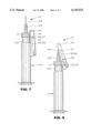
- FIG. 7 is a side elevational view of the hypodermic needle capping device attached to a hypodermic syringe and shown positioned in the downward syringe usable position.
- FIG. 8 is a side elevational view of the hypodermic needle capping device attached to a hypodermic syringe and shown positioned in an upward syringe non-usable position.
- the best mode for carrying out the invention is presented in terms of a preferred embodiment for a hypodermic needle capping device 10, hereinafter "device 10".
- the device is designed to allow a health worker, such as a doctor, nurse, or blood technician to easily and safely use a hypodermic needle on a patient while significantly reducing the risk of accidently puncturing themselves, as well as the patient.
- a device such as this is not merely a benefit, but is also a potential lifesaver as well.
- the device 10, as shown in FIGS. 1-8 is comprised of the following major elements: a collar 12, a snap-lock structure 24, a locking tab 38, a slide member retaining structure 42, a slide member 54, an outer channel 60, and an inner channel 70.
- a hypodermic syringe 100 having a needle hub 102, a needle 104, a hollow barrel 106 with an upper edge 108, a plunger receiving lower edge 110, and a cap 112 are also shown. It would be noted that the cap 112 is designed to fit over the needle hub 102 and to protect the needle 104 prior to use. When the syringe 100 is about to be used, the cap 112 is removed, thus exposing the needle 104.
- the device 10 functions in combination with the hypodermic syringe 100, and is comprised of the collar 12 which has an upper edge 14, a lower edge 16, an outside diameter 18, and an inside diameter 20 that is press-fitted over the upper edge 108 of the syringe's 100 hollow barrel 106.
- the outside diameter 18 of the collar 12 has a series of vertical serrations 22 which aid in sliding and positioning the collar 12 over the hollow barrier 106.
- the snap-lock structure 24 is integrally molded with the collar 12 of a plastic and is comprised of a longitudinal member 26 having an outer surface 28, an inner surface 30, an upper edge 32 and a lower edge 34.
- the inner surface 30 is attached to the outside diameter 18 of the collar 12 as shown in FIG. 2.
- the locking tab 38 extends outward from the upper edge 32 and outer surface 28 of the longitudinal member 26, as shown in FIG. 1.
- the locking tab 38 can be designed as either a straight locking tab, or preferably as a locking barb 40, as shown in FIG. 2, which provides a positive lock upon the slide member 54 that prevents the slide member 54 from being removed once it has been placed in a needle safe position.
- the final element of the snap-lock structure 24 is the slide member retaining structure 42.
- the retaining structure 42 extends outward from the longitudinal member 26 and has a first side 44 from where extends outward a first guide pin 46.
- a second guide pin 50 extends outward from a second side 48, as shown in FIG. 3.
- the inner surface 30 of the snap-lock structure 24 has a radiused surface 36, as shown in FIG. 4, that corresponds with the radiused surface of the hollow barrier 106.
- the slide member 54 is utilized.
- the slide member 54 as shown in FIGS. 5, 6, 7 and 8, is comprised of a central longitudinal member 56 having a locking barb receiving and locking slot 58; an outer channel 60 having an upper edge 62 and a lower edge 64, with the lower edge 64 having a closed surface 66; and an inner channel 70 having an upper edge 72 and a lower edge 74.
- the upper edge 72 includes a needle-point barrier 76, which extends across to the upper edge 62 of the outer channel 60.
- a needle tip engaging pad 94 which further provides a securing means for the needle 104.
- the slot 58 is located substantially one-third the distance from the lower edge 64 of the outer channel 60 of the slide member 54. In order to provide a high degree of structural integrity to the device 10, all of the elements of the slide member 54 are integrally molded of plastic.
- the inner channel 70 further has a first side 78 having a first longitudinal pin traversing slot 80, which is comprised of an upper edge 82 and a lower edge 84 as shown in FIG. 5.
- a second side 86 has a second longitudinal pin traversing slot 88, which is also comprised of an upper edge 90 and a lower edge 92.
- the slide member 54 is dimensioned to be slidably attached when the first and second longitudinal pin traversing slots 80,88 are inserted over each of the first and second guide pins 46,50, respectively, as shown in FIGS. 7 and 8.
- the slide member 54 is designed to include a protuberance 96 that extends outward from an inner edge of the first and second pin traversing slots 80, 88, as shown in FIGS. 5, 7 and 8.
- the protuberances 96 are positioned whereby when the slide member 54 is in a downward position, the protuberances 96 are in contact with the lower surface of the first and second guide pins 46, 50 as shown in FIG. 7.
- the protuberances 96 function to maintain the slide member 54 in the downward position until such time that the user pushes the slide member 54 upward, overcoming the resistance of the protuberances 96 and allowing the slide member 54 to be placed in the upward position as shown in FIG. 8.
- the slide member 54 When the hypodermic syringe 100 is being used the slide member 54 is positioned in a downward direction with the respective upper edges 82,90 of the first and second pin traversing slots 80,88 as shown in FIG. 7. After the hypodermic syringe 100 has been used, but prior to disposal, the slide member 54 is slid upward until the locking tab 38 engages the receiving and locking slot 58. Once engaged, as shown in FIG. 8, the needle 102 is safely located adjacent the needle-point barrier 76 and presents no danger from an un-intentional puncturing.
Abstract
Description
______________________________________
U.S. PAT. NO. INVENTOR    ISSUED
______________________________________
5,947,933     Reichenbach 7 September 1999
5,899,883     Chern       3 May 1999
5,713,871     Stock       3 February 1998
5,348,544     Sweeney     20 September 1994
4,834,716     Ogle II     30 May 1989
______________________________________
______________________________________
U.S. PAT. NO. INVENTOR     ISSUED
______________________________________
5,938,641     Villanueva   17 August 1999
5,891,092     Castellano   6 April 1999
5,885,256     Chern        23 March 1999
5,876,382     Erickson     2 March 1999
______________________________________
Claims (16)
Priority Applications (1)
| Application Number | Priority Date | Filing Date | Title |
|---|---|---|---|
| US09/487,185 US6139533A (en) | 2000-01-19 | 2000-01-19 | Hypodermic needle capping device |
Applications Claiming Priority (1)
| Application Number | Priority Date | Filing Date | Title |
|---|---|---|---|
| US09/487,185 US6139533A (en) | 2000-01-19 | 2000-01-19 | Hypodermic needle capping device |
Publications (1)
| Publication Number | Publication Date |
|---|---|
| US6139533A true US6139533A (en) | 2000-10-31 |
Family
ID=23934735
Family Applications (1)
| Application Number | Title | Priority Date | Filing Date |
|---|---|---|---|
| US09/487,185 Expired - Fee Related US6139533A (en) | 2000-01-19 | 2000-01-19 | Hypodermic needle capping device |
Country Status (1)
| Country | Link |
|---|---|
| US (1) | US6139533A (en) |
Cited By (9)
| Publication number | Priority date | Publication date | Assignee | Title |
|---|---|---|---|---|
| US6648855B2 (en) | 1999-08-23 | 2003-11-18 | Becton, Dickinson And Company | Safety needle assembly |
| US6699217B2 (en) | 1999-08-23 | 2004-03-02 | Becton, Dickinson And Company | Safety needle assembly |
| US6780169B2 (en) | 1999-08-23 | 2004-08-24 | Becton, Dickinson And Company | Safety shield assembly |
| US20050187493A1 (en) * | 2004-02-25 | 2005-08-25 | Becton, Dickinson And Company | Safety blood collection holder |
| US20100211014A1 (en) * | 2002-07-03 | 2010-08-19 | Novo Nordisk A/S | Needle Mounting System And A Method For Mounting A Needle Assembly |
| US7854723B2 (en) | 2001-05-22 | 2010-12-21 | Becton, Dickinson And Company | Needle shield assembly having hinged needle shield |
| US8038654B2 (en) | 2007-02-26 | 2011-10-18 | Becton, Dickinson And Company | Syringe having a hinged needle shield |
| US8287498B2 (en) | 2002-06-11 | 2012-10-16 | Bd Medical Products, Pte. Ltd. | Flashback blood collection needle with needle shield |
| USD675316S1 (en) * | 2007-08-22 | 2013-01-29 | Novo Nordisk A/S | Needle hub |
Citations (4)
| Publication number | Priority date | Publication date | Assignee | Title |
|---|---|---|---|---|
| US5116325A (en) * | 1990-06-06 | 1992-05-26 | Paterson Donald W | Needle assembly |
| US5207653A (en) * | 1989-08-18 | 1993-05-04 | Sabiha Janjua | Safety needle and cap combination device |
| US5462534A (en) * | 1994-10-19 | 1995-10-31 | Moldex Plastics & Tool Inc. | Needle assembly for use with a syringe |
| US5913846A (en) * | 1996-06-13 | 1999-06-22 | Becton, Dickinson And Company | Shielded needle assembly |
-
2000
- 2000-01-19 US US09/487,185 patent/US6139533A/en not_active Expired - Fee Related
Patent Citations (4)
| Publication number | Priority date | Publication date | Assignee | Title |
|---|---|---|---|---|
| US5207653A (en) * | 1989-08-18 | 1993-05-04 | Sabiha Janjua | Safety needle and cap combination device |
| US5116325A (en) * | 1990-06-06 | 1992-05-26 | Paterson Donald W | Needle assembly |
| US5462534A (en) * | 1994-10-19 | 1995-10-31 | Moldex Plastics & Tool Inc. | Needle assembly for use with a syringe |
| US5913846A (en) * | 1996-06-13 | 1999-06-22 | Becton, Dickinson And Company | Shielded needle assembly |
Cited By (14)
| Publication number | Priority date | Publication date | Assignee | Title |
|---|---|---|---|---|
| US6699217B2 (en) | 1999-08-23 | 2004-03-02 | Becton, Dickinson And Company | Safety needle assembly |
| US6780169B2 (en) | 1999-08-23 | 2004-08-24 | Becton, Dickinson And Company | Safety shield assembly |
| US6648855B2 (en) | 1999-08-23 | 2003-11-18 | Becton, Dickinson And Company | Safety needle assembly |
| US7854723B2 (en) | 2001-05-22 | 2010-12-21 | Becton, Dickinson And Company | Needle shield assembly having hinged needle shield |
| US8287498B2 (en) | 2002-06-11 | 2012-10-16 | Bd Medical Products, Pte. Ltd. | Flashback blood collection needle with needle shield |
| US8708964B2 (en) | 2002-06-11 | 2014-04-29 | Bd Medical Products, Pte. Ltd. | Flashback blood collection needle with needle shield |
| US8277408B2 (en) | 2002-06-14 | 2012-10-02 | Becton, Dickinson And Company | Safety needle assembly |
| US20100211014A1 (en) * | 2002-07-03 | 2010-08-19 | Novo Nordisk A/S | Needle Mounting System And A Method For Mounting A Needle Assembly |
| US8137325B2 (en) | 2002-07-03 | 2012-03-20 | Novo Nordisk A/S | Needle mounting system and a method for mounting a needle assembly |
| US8579869B2 (en) | 2002-07-03 | 2013-11-12 | Novo Nordisk A/S | Needle mounting system and a method for mounting a needle assembly |
| US20050187493A1 (en) * | 2004-02-25 | 2005-08-25 | Becton, Dickinson And Company | Safety blood collection holder |
| US8226576B2 (en) * | 2004-02-25 | 2012-07-24 | Becton, Dickinson And Company | Safety blood collection holder |
| US8038654B2 (en) | 2007-02-26 | 2011-10-18 | Becton, Dickinson And Company | Syringe having a hinged needle shield |
| USD675316S1 (en) * | 2007-08-22 | 2013-01-29 | Novo Nordisk A/S | Needle hub |
Similar Documents
| Publication | Publication Date | Title |
|---|---|---|
| US5411492A (en) | Hypodermic needle protector | |
| US5222945A (en) | Hypodermic syringe with protective shield | |
| US5219338A (en) | Safety syringe with collapsible needle guard | |
| JP2956965B2 (en) | Needle assembly with locking enclosure | |
| US4883469A (en) | Guard assembly for hypodermic needle | |
| EP0916354B1 (en) | Single-use safety syringe | |
| EP0540217B1 (en) | Holder for double-ended needles | |
| US5836920A (en) | Needle guard | |
| US4994046A (en) | Needle guard for syringe | |
| US7083600B2 (en) | Safety needle and shield | |
| US6106500A (en) | Hypodermic needle assembly | |
| US5207699A (en) | Lancet handling and disposal assembly | |
| EP0864335B2 (en) | Syringe guard | |
| US5246427A (en) | Safety hypodermic needle and shielding cap assembly | |
| US4826491A (en) | Needle bearing medical device with three-position shield | |
| EP0702973B1 (en) | Manually pivoted barrier assembly for a piercing element | |
| US7241275B2 (en) | Intradermal needle | |
| US5163907A (en) | Single use retractable needle syringe | |
| US5658255A (en) | Needle apparatus | |
| US20120238966A1 (en) | Needle tip guard for percutaneous entry needles | |
| US6485469B1 (en) | Shielded dental safety needle | |
| US20070088261A1 (en) | Hypodermic needle safety cap apparatus | |
| US7001364B1 (en) | Needle safety cap device | |
| MXPA02007974A (en) | Automatically operable safety shield system for syringes. | |
| US5643222A (en) | Hypodermic needle assembly |
Legal Events
| Date | Code | Title | Description |
|---|---|---|---|
| AS | Assignment |
Owner name: INTERNATIONAL MEDICATION SYSTEM LTD, CALIFORNIA Free format text: ASSIGNMENT OF ASSIGNORS INTEREST;ASSIGNORS:XIA, FRANK ZHISHI;MAIER, GUNTHER;ZHANG, JACK YONGFENG;AND OTHERS;REEL/FRAME:011523/0678 Effective date: 20010201 |
|
| FPAY | Fee payment |
Year of fee payment: 4 |
|
| FEPP | Fee payment procedure |
Free format text: PAT HOLDER NO LONGER CLAIMS SMALL ENTITY STATUS, ENTITY STATUS SET TO UNDISCOUNTED (ORIGINAL EVENT CODE: STOL); ENTITY STATUS OF PATENT OWNER: LARGE ENTITY Free format text: PAYOR NUMBER ASSIGNED (ORIGINAL EVENT CODE: ASPN); ENTITY STATUS OF PATENT OWNER: LARGE ENTITY |
|
| REFU | Refund |
Free format text: REFUND - PAYMENT OF MAINTENANCE FEE, 8TH YR, SMALL ENTITY (ORIGINAL EVENT CODE: R2552); ENTITY STATUS OF PATENT OWNER: LARGE ENTITY |
|
| FPAY | Fee payment |
Year of fee payment: 8 |
|
| REMI | Maintenance fee reminder mailed | ||
| LAPS | Lapse for failure to pay maintenance fees | ||
| STCH | Information on status: patent discontinuation |
Free format text: PATENT EXPIRED DUE TO NONPAYMENT OF MAINTENANCE FEES UNDER 37 CFR 1.362 |
|
| FP | Lapsed due to failure to pay maintenance fee |
Effective date: 20121031 |
|
| AS | Assignment |
Owner name: CAPITAL ONE, NATIONAL ASSOCIATION, MARYLAND Free format text: SECURITY INTEREST;ASSIGNORS:AMPHASTAR PHARMACEUTICALS, INC.;INTERNATIONAL MEDICATION SYSTEMS, LIMITED;ARMSTRONG PHARMACEUTICALS, INC.;REEL/FRAME:057086/0313 Effective date: 20210804 |
|
| AS | Assignment |
Owner name: INTERNATIONAL MEDICATION SYSTEMS, LIMITED, CALIFORNIA Free format text: RELEASE BY SECURED PARTY;ASSIGNOR:CAPITAL ONE, NATIONAL ASSOCIATION, AS AGENT;REEL/FRAME:064119/0605 Effective date: 20230629 Owner name: ARMSTRONG PHARMACEUTICALS, INC., CALIFORNIA Free format text: RELEASE BY SECURED PARTY;ASSIGNOR:CAPITAL ONE, NATIONAL ASSOCIATION, AS AGENT;REEL/FRAME:064119/0605 Effective date: 20230629 |