US6146347A - Appliance and method for treating carpal tunnel syndrome - Google Patents
Appliance and method for treating carpal tunnel syndrome Download PDFInfo
- Publication number
- US6146347A US6146347A US09/088,265 US8826598A US6146347A US 6146347 A US6146347 A US 6146347A US 8826598 A US8826598 A US 8826598A US 6146347 A US6146347 A US 6146347A
- Authority
- US
- United States
- Prior art keywords
- splint
- hand
- dorsal
- thenar
- hypothenar
- Prior art date
- Legal status (The legal status is an assumption and is not a legal conclusion. Google has not performed a legal analysis and makes no representation as to the accuracy of the status listed.)
- Expired - Lifetime
Links
Images


Classifications
-
- A—HUMAN NECESSITIES
- A61—MEDICAL OR VETERINARY SCIENCE; HYGIENE
- A61F—FILTERS IMPLANTABLE INTO BLOOD VESSELS; PROSTHESES; DEVICES PROVIDING PATENCY TO, OR PREVENTING COLLAPSING OF, TUBULAR STRUCTURES OF THE BODY, e.g. STENTS; ORTHOPAEDIC, NURSING OR CONTRACEPTIVE DEVICES; FOMENTATION; TREATMENT OR PROTECTION OF EYES OR EARS; BANDAGES, DRESSINGS OR ABSORBENT PADS; FIRST-AID KITS
- A61F5/00—Orthopaedic methods or devices for non-surgical treatment of bones or joints; Nursing devices; Anti-rape devices
- A61F5/01—Orthopaedic devices, e.g. splints, casts or braces
- A61F5/0102—Orthopaedic devices, e.g. splints, casts or braces specially adapted for correcting deformities of the limbs or for supporting them; Ortheses, e.g. with articulations
- A61F5/012—Orthopaedic devices, e.g. splints, casts or braces specially adapted for correcting deformities of the limbs or for supporting them; Ortheses, e.g. with articulations inflatable
-
- A—HUMAN NECESSITIES
- A61—MEDICAL OR VETERINARY SCIENCE; HYGIENE
- A61F—FILTERS IMPLANTABLE INTO BLOOD VESSELS; PROSTHESES; DEVICES PROVIDING PATENCY TO, OR PREVENTING COLLAPSING OF, TUBULAR STRUCTURES OF THE BODY, e.g. STENTS; ORTHOPAEDIC, NURSING OR CONTRACEPTIVE DEVICES; FOMENTATION; TREATMENT OR PROTECTION OF EYES OR EARS; BANDAGES, DRESSINGS OR ABSORBENT PADS; FIRST-AID KITS
- A61F13/00—Bandages or dressings; Absorbent pads
- A61F13/10—Bandages or dressings; Absorbent pads specially adapted for fingers, hands, or arms; Finger-stalls; Nail-protectors
- A61F13/107—Bandages or dressings; Absorbent pads specially adapted for fingers, hands, or arms; Finger-stalls; Nail-protectors for wrist support ; Compression devices for tennis elbow (epicondylitis)
- A61F13/108—Openable readjustable
-
- A—HUMAN NECESSITIES
- A61—MEDICAL OR VETERINARY SCIENCE; HYGIENE
- A61F—FILTERS IMPLANTABLE INTO BLOOD VESSELS; PROSTHESES; DEVICES PROVIDING PATENCY TO, OR PREVENTING COLLAPSING OF, TUBULAR STRUCTURES OF THE BODY, e.g. STENTS; ORTHOPAEDIC, NURSING OR CONTRACEPTIVE DEVICES; FOMENTATION; TREATMENT OR PROTECTION OF EYES OR EARS; BANDAGES, DRESSINGS OR ABSORBENT PADS; FIRST-AID KITS
- A61F5/00—Orthopaedic methods or devices for non-surgical treatment of bones or joints; Nursing devices; Anti-rape devices
- A61F5/01—Orthopaedic devices, e.g. splints, casts or braces
- A61F5/0102—Orthopaedic devices, e.g. splints, casts or braces specially adapted for correcting deformities of the limbs or for supporting them; Ortheses, e.g. with articulations
- A61F5/0104—Orthopaedic devices, e.g. splints, casts or braces specially adapted for correcting deformities of the limbs or for supporting them; Ortheses, e.g. with articulations without articulation
- A61F5/0118—Orthopaedic devices, e.g. splints, casts or braces specially adapted for correcting deformities of the limbs or for supporting them; Ortheses, e.g. with articulations without articulation for the arms, hands or fingers
Definitions
- This invention pertains to the field of methods and appliances for the treatment of carpal tunnel syndrome.
- Carpal tunnel syndrome is caused by a deleterious increase in pressure on the median nerve which passes through the carpal tunnel (or canal) in the hand, adjacent 10 the wrist.
- the deleterious increase in pressure which is brought on by prolonged repetitive motion of the hand and digits, is often caused by inflammation or damage to tendons for the hand which pass through the carpal tunnel along with the median nerve. Pressure increases can also be caused by narrowing of the carpal canal and by generalized swelling of the structures in the hand.
- the carpal tunnel is formed by the eight carpal bones of the hand adjacent the wrist, which bones are arranged in two rows forming a generally U-shaped inverted arch-like "tunnel" structure.
- the three large carpal bones of the proximal row i.e., closest to the chest
- the scaphoid, lunate, and triquetrum are the scaphoid, lunate, and triquetrum; the smaller pisiform bone sits on the palmar surface of the triquetrum.
- the distal row, from lateral to medial, consists of the trapezium, trapezoid, capitate, and hamate carpal bones.
- the vault of the carpal tunnel is formed by the carpal ligament and the flexor retinaculum.
- Nine tendons, their tendon sheaths, and the median nerve pass through the tunnel.
- the carpal ligament is made of collagen and elastin and extends from the pisiformis and hamulus of hamate bones on the ulnar aspect of the tunnel to the tubercle (i.e., projection) of trapezium and the tubercle of the scaphoid bones on the radial (i.e. lateral) aspect of the carpal tunnel.
- the flexor retinaculum also stretches across the carpal tunnel and attaches to, on the medial aspect of the carpal tunnel, the pisiform bone and the hook of hamate, and, on the lateral aspect, the tubercle of the scaphoid and trapezium bones.
- the proximal border of the flexor retinaculum corresponds generally to the transverse skin crease at the base of the hand/wrist.
- Symptoms of carpal tunnel syndrome include tingling sensation in the hand, discomfort, numbness, and pain localized in the hand or radiating up the arm to the shoulder. All of these symptoms can occur during the day or can make the patients wake up at night. In advanced cases, there is atrophy and weakness of the thenar area of the hand which may weaken the grip and cause objects to fall out of the hand.
- Surgical treatment consists of making an incision on the palmar aspect of the hand and splitting the carpal ligament, thus partially opening the carpal tunnel and relieving the pressure.
- This procedure while often successful, may have negative consequences, which include, but are not limited to, non-resolution of symptoms often requiring a second surgery, pain in the area of the scar, and injury to the superficial palmar branch of the median nerve causing persistent neurologic symptoms. Understandably, surgical treatment is often considered as a last option.
- Conservative , non-invasive treatment includes immobilizing the hand and wrist, usually with a resting splint to maintain the hand in a neutral position (such as disclosed in U.S. Pat. No. 5,014,689), mechanical stretching of the carpal ligament (such as disclosed in U.S. Pat. No. 5,468,220), care provider administered massage, anti-inflammatory medications, cortisone injections, and avoidance of the daily activities which cause the symptoms, including a change in job.
- none of the known methods and devices provide for precise and controllable stretching of both the carpal ligament and the flexor retinaculum in a comfortable manner.
- the objective of the present invention is to stretch the carpal ligament and the flexor retinaculum, as well as the superficial structures of the hand, in a safe manner under precise patient control.
- the new method and new appliance of prevention are inexpensive, prevent progression of carpal tunnel syndrome and provide relief from symptoms by increasing the cross sectional area of the carpal tunnel, thus decreasing compression on the median nerve and decreasing the resulting symptoms.
- Controlled and monitored use of the appliance of the invention dynamically treats carpal tunnel syndrome through the application of pressure to large portions of the palm of the hand (in the thenar and hypothenar areas) while at the same time providing application of pressure, in the opposite direction, to a large portion of the dorsum of the hand with an air bladder.
- This novel procedure stretches the carpal ligament, the flexor retinaculum, and superficial structures of the hand in the palmar aspect of the hand, in a readily, safely controllable and comfortable manner.
- the constitutions of the carpal ligament and the flexor retinaculum are soft tissue composed of collagen and elastin, stretching the carpal ligament and the flexor retinaculum is effective for decreasing compression on the median nerve by increasing the diameter of the tunnel and decreasing the rigidity of the retinaculum and the carpal ligament, thus alleviating the symptoms of carpal tunnel syndrome.
- FIG. 1 is a top plan view of a first embodiment of the new therapeutic appliance of the invention
- FIG. 2 is a bottom plan view of the appliance of FIG. 1;
- FIG. 3 is a distal end elevational view of the appliance of FIG. 1;
- FIG. 4 is a top plan view of a second embodiment of the therapeutic appliance
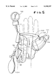
- FIG. 5 is a top plan view of the appliance of FIG. 4, mounted on a hand;
- FIG. 6 is a bottom plan view of the appliance of FIG. 5;
- FIG. 7 is a distal end elevational view of the appliance of FIG. 4, illustrating the method of donning the appliance
- FIG. 8 is a proximal end elevational schematic view of the carpal bones of the hand subject to forces applied by the appliance of FIG. 4;
- FIG. 9 is a proximal end elevational schematic view of the carpal bones of the hand as displaced by the forces indicated in FIG. 8;
- FIG. 10 is a skeletal view of the palmar aspect of the right hand.
- a first embodiment of the therapeutic appliance 10 of the invention is applied to the hand 12 of a person.
- the appliance 10 includes a thenar portion 14 which applies pressure to a substantial portion of the thenar area of the palmar aspect of the hand 12 and a hypothenar portion 18 which applies pressure to a substantial portion of the hypothenar area of the palmar aspect of the hand 12.
- a dorsal portion 20 Opposite, and spaced from the thenar and hypothenar portions 14, 18 is a dorsal portion 20 which is adapted to support the dorsal aspect of the hand.
- the splint 10, including the thenar, hypothenar and dorsal portions 14, 18, 20, is sized and shaped to conform to the shape of the associated areas of the hand such that the hand is closely received within the splint.
- the thenar and hypothenar portions 14, 18 are each located between opposite sides of the dorsal portion and are connected to the dorsal portion by lateral and medial joining portions 15, 19 respectively.
- the lateral joining portion 15 includes a hole 42 for the thumb 16 and is adapted to maintain the thumb in radial abduction.
- a thumb support extension 21 preferably extends outwardly from the thenar portion 14 to prevent the thumb 16 from flexing during treatment.
- the thumb support extension 21 can be integrally connected to the thenar portion 14, formed from the material removed from the lateral joining portion 15 when forming the thumb hole 42.
- An inflatable bladder 22 is attached to an interior surface 24 of the dorsal portion 20 of the appliance 10, preferably with a fastener 23, such as a Velcro® hook-and-loop fastener, or the like.
- the bladder 22 is located between opposite sides 25, 27 of the appliance 10 to apply pressure generally to the center of the dorsal aspect of the hand 12 between the thenar and hypothenar areas of the palmar aspect of the hand, and is sized to apply pressure to a substantial portion of the dorsal aspect of the hand.
- the source of pressurized fluid 24 preferably includes a release valve 30 to decrease the pressure in the bladder 22 when desirable.
- a pressure gauge 32 or sphygmomanometer is also preferably connected to the bladder 22 via a second conduit 34 to monitor the pressure in the bladder 22 in, for example mm Hg.
- the appliance 10 includes orifices 36, 38 (best seen in FIG. 2) through which the first and second conduits 28, 34 pass.
- the appliance 10 may also include an adjustable, automatic pressure release valve (not shown) or other suitable means to set a maximum allowable pressure for the bladder 22.
- the hand 12 is inserted through a first end 40 of the appliance 10, between the bladder 22 and the thenar and hypothenar portions 14, 18, with the bladder 22 in a deflated condition.
- the thumb 14 is inserted through a thumb hole 42 formed between the thenar and dorsal portions 14, 20, with the fingers 44 projecting past a second end 45 of the appliance 10.
- the thumb 16 is maintained in radial abduction, as shown.
- the thenar, hypothenar, and dorsal portions 14, 18, and 20 of the appliance 10 are preferably integrally formed from relatively rigid material sized and shaped to envelop the hand 12. Suitable material is preferably between 1/16" and 1/4" thick Rolyan® Aquaplast® splinting material available from Smith and Nephew, Inc. in Germantown, Wis., or the like.
- the appliance 10 is adapted to be manufactured in general "small-medium-large" sizes, each for a limited range of hand shapes and sizes. However, the appliance 10 is preferably individually sized for each user by using the patient's hand as a model or mold. In addition, the appliance may include ventilation holes to allow forced or convective cooling air to pass over the hand during treatment.
- the dorsal portion 20 of the appliance 10 is preferably straight in a longitudinal direction and includes a proximal end portion 48 which extends toward the forearm 58, beyond the proximal end 60 of the hand 12 to prevent the hand 12 from extending upward during treatment.
- the hypothenar portion 18 of the appliance is also preferably straight in a longitudinal direction, and includes a proximal end portion 62 which extends toward the forearm 58, beyond the proximal end 60 of the hand 12 to prevent the hand 12 from flexing during treatment.
- the hand 12 is substantially maintained in the neutral position during treatment and is substantially prevented from flexing or extending.
- a wrist strap (not shown) may be connected to the dorsal portion 20 of the appliance 10, around the forearm 58 to maintain the hand 12 in the neutral position.
- the bladder 22 is inflated with the source of pressurized fluid 24 to apply force to the dorsal aspect of the hand 12, which force is balanced by separate forces applied in an opposite direction by the thenar and hypothenar portions 14, 18 to their respective areas of the palmar aspect of the hand.
- this arrangement of forces causes the distance between certain carpal bones of the hands to increase, namely the pisiformis and hamulus of hamate bones, thereby stretching the carpal ligament and the flexor retinaculum.
- the pressure is maintained at a preferably constant level for a period of time to induce permanent or semipermanent elongation of the carpal ligament and the flexor retinaculum, thereby increasing the diameter of the carpal tunnel and decreasing the cause and symptoms of carpal tunnel syndrome.
- the appliance 10 preferably maintains the hand 12 in the neutral position during treatment.
- the thumb 16 is maintained in radial abduction. This position minimizes the natural internal pressure in the carpal tunnel which aids in treatment.
- the upward force on the dorsal aspect of the hand 12 balanced in part by the opposing force on the hypothenar area of the palmar aspect of the hand 12, will naturally cause the thumb 16 to move into a mild or slight retroposition (i.e., slightly bent downward with respect to the palm).
- the wide distribution of forces applied to the hand increases the comfort of the appliance during treatment, and minimizes any detrimental effects of the pressure to the epidermis, and increases the length of time for which the appliance can be used.
- the hypothenar portion 18 of the appliance 10 extends from adjacent the distal ends of the metacarpal bones of the fourth and fifth digits on the palmar aspect of the hand to a position preferably about three inches proximal to (i.e., above, or closer to the chest than) the pisiform bone.
- the appliance 10 covers the hypothenar muscles and a portion of the ulnar aspect of the distal forearm.
- the dorsal portion 20 of the appliance 10 extends from adjacent the distal ends of the metacarpal bones of digits one through four, inclusive, to a position (preferably three inches) proximal to the wrist joint.
- a projection extends from the radial aspect of the dorsal portion 20.
- the hypothenar portion 18 also preferably includes a proximal end portion 62.
- This proximal end portion 62 preferably extends beyond the carpal bones at the proximal end 60 of the hand 12, thereby essentially immobilizing the hand 12 during treatment.
- the dorsal portion 20 goes around the posterior aspect of the hand 12 covering from adjacent the distal ends of the metacarpal bones of digits one to four, inclusive, to three inches proximal to the wrist joint.
- the bladder 22 preferably extends longitudinally about 3 inches, from adjacent the distal ends of the metacarpal bones of at least the third through fourth fingers to adjacent or over the carpal bones, and transversely, about 2 inches.
- the dorsal portion 20 of the appliance preferably has a distal end portion 68 which extends longitudinally, beyond the bladder 22, to maintain the hand 12 in the neutral position during treatment.
- Carpal tunnel treatment protocols using the appliance 10 consist of applying either constant or varying pressure to the dorsal aspect of the hand for predetermined periods of time at preferably regular intervals.
- the design of the appliance 10 is such that, once given proper instruction, treatment can be administered by the patient without the aid of a physician or other assistant.
- the pressurized source of fluid 24 and the pressure gauge 32 provide that the forces applied to the hand 12 can be accurately and easily monitored and duplicated. In addition, the forces can be adjusted while the appliance 10 is fully mounted on the hand 12.
- the appliance 10 can include a means to limit the maximum amount of pressure in the bladder 22, such as a pressure release valve, to prevent accidental overstressing of the carpal ligament and flexor retinaculum.
- an alternate preferred embodiment of the appliance 110 includes a detachable thenar portion 114 which is designed to aid in the mounting of the appliance for extreme cases of carpal tunnel syndrome.
- the detachable thenar portion 114 extends outwardly over the palmar aspect of the hand 12 and is secured to both a dorsal portion 120 and a thumb support extension 121 of the dorsal portion by a securing means 70 such as an elastic strap 72 and releasable fastening means, such as Velcro® hook-and-loop fasteners, snaps, or the like.
- the securing means 70 is preferably connected to the dorsal portion 120, the thumb support extension 121, the detachable thenar portion 114 and the hypothenar portion 118 by fasteners 74, such as Velcro® hook-and-loop fasteners attached to the areas of contact.
- the second embodiment of the appliance 110 includes a bladder 122, a source of pressurized fluid 124, and a pressure gauge 132 for applying pressure to the dorsal aspect of the hand 12.
- the medial aspect of the hand is inserted between the hypothenar position 118 and the dorsal portion 120, with the thumb 16 resting on the thumb support extension 121 of the dorsal portion 120, and the detachable thenar position 114 and the securing means 70 in a detached position, as shown in FIG. 4.
- the securing means 70 has one end 80 attached to the appliance 110, preferably adjacent a medial side 125 of a distal end portion 84 of the hypothenar portion 118.
- the securing means 70 is wrapped around the thumb 16, thereby aligning the detachable thenar portion 114 with the thenar area of the palmar aspect of the hand 12 and confining the thumb 16 between the thenar portion 14 and the thumb-support extension 121 of the dorsal portion 120. This secures the thumb 16 in radial abduction.
- the securing means 70 is then extended underneath the dorsal portion 120 and a second end 82 is attached to the appliance 110, preferably adjacent the medial side 125 near the proximal end portions 148, 86, respectively of either the dorsal portion 120 or the hypothenar portion 118.
- the appliance 110 will function to stretch the carpal ligament and flexor retinaculum as discussed in conjunction with the first embodiment of the appliance.
- the appliance and method of the invention provide a novel, convenient, and effective means to treat carpal tunnel syndrome.
- the appliance of the invention of relatively inexpensive, comfortable, and easy to operate. Furthermore, the force applied to the hand can be precisely set, monitored, and adjusted, thereby increasing the effectiveness of the appliance and method.
Abstract
Description
Claims (11)
Priority Applications (1)
| Application Number | Priority Date | Filing Date | Title |
|---|---|---|---|
| US09/088,265 US6146347A (en) | 1998-06-01 | 1998-06-01 | Appliance and method for treating carpal tunnel syndrome |
Applications Claiming Priority (1)
| Application Number | Priority Date | Filing Date | Title |
|---|---|---|---|
| US09/088,265 US6146347A (en) | 1998-06-01 | 1998-06-01 | Appliance and method for treating carpal tunnel syndrome |
Publications (1)
| Publication Number | Publication Date |
|---|---|
| US6146347A true US6146347A (en) | 2000-11-14 |
Family
ID=22210365
Family Applications (1)
| Application Number | Title | Priority Date | Filing Date |
|---|---|---|---|
| US09/088,265 Expired - Lifetime US6146347A (en) | 1998-06-01 | 1998-06-01 | Appliance and method for treating carpal tunnel syndrome |
Country Status (1)
| Country | Link |
|---|---|
| US (1) | US6146347A (en) |
Cited By (50)
| Publication number | Priority date | Publication date | Assignee | Title |
|---|---|---|---|---|
| US6475174B1 (en) | 2001-10-25 | 2002-11-05 | James C. Y. Chow | Dorsal compartment brace |
| US6496984B1 (en) * | 2001-10-25 | 2002-12-24 | James C. Y. Chow | CMC joint splint |
| WO2003007804A2 (en) | 2001-07-18 | 2003-01-30 | Porrata Group Llc | Apparatus and method for treating carpal tunnel syndrome |
| US20030034246A1 (en) * | 1998-12-02 | 2003-02-20 | Meilin Liu | Oxygen sensor and emission control system |
| WO2003017884A1 (en) | 2001-08-27 | 2003-03-06 | M.D. Brothers, Inc. | Non-invasive apparatus and method for treating carpal tunnel syndrome |
| WO2003017885A1 (en) | 2001-08-27 | 2003-03-06 | M.D. Brothers, Inc. | Automatic apparatus and method for treating carpal tunnel syndrome |
| WO2003017886A1 (en) | 2001-08-27 | 2003-03-06 | M.D. Brothers, Inc. | Adaptable apparatus and method for treating carpal tunnel syndrome |
| WO2003017888A1 (en) | 2001-08-27 | 2003-03-06 | M. D. Brothers, Inc. | Configurable apparatus and method for treating carpal tunnel syndrome |
| WO2003017887A1 (en) | 2001-08-27 | 2003-03-06 | M.D. Brothers, Inc. | Adjustable apparatus and method for treating carpal tunnel syndrome |
| US6585669B2 (en) | 1996-06-07 | 2003-07-01 | Medical Dynamics Llc | Medical device for applying cyclic therapeutic action to subject's foot |
| US20030144692A1 (en) * | 2002-01-28 | 2003-07-31 | Williams George Roger | Co-dynamic adjustable orthotic appliance for carpal tunnel syndrome |
| US20030217404A1 (en) * | 2002-05-21 | 2003-11-27 | Deborah Hurst | Erogonomic compression glove for hand, wrist, thumb and forearm support |
| US6685661B2 (en) | 2000-12-14 | 2004-02-03 | Medical Dynamics Llc, Usa | Medical device for applying cyclic therapeutic action to a subject's foot |
| US20040092853A1 (en) * | 2001-03-13 | 2004-05-13 | Michael Degun | Orthopaedic splint |
| US6790192B2 (en) | 2002-12-02 | 2004-09-14 | Medical Products Marketing, Inc. | Hand and wrist brace and kit |
| US20050203451A1 (en) * | 2004-03-10 | 2005-09-15 | Daniel Reis | Immobilizing and supporting inflatable splint apparatus |
| US20060052730A1 (en) * | 2004-09-07 | 2006-03-09 | Hargrave David C | Fracture brace |
| US20060069335A1 (en) * | 2004-09-27 | 2006-03-30 | John Fritsch | Wrist brace |
| US20070100266A1 (en) * | 2005-10-27 | 2007-05-03 | Aircast Llc | Fracture brace |
| US20070185527A1 (en) * | 2005-10-18 | 2007-08-09 | Ab Ortho, Llc | Apparatus and method for treating soft tissue injuries |
| US20080163876A1 (en) * | 2007-01-10 | 2008-07-10 | Phelan Eileen J | Device for training wearer wrist position and for reminding wearer of wrist position |
| US20080262536A1 (en) * | 2007-04-18 | 2008-10-23 | Ab Ortho, Llc | Apparatus for treating soft tissue injuries during physical activity |
| US7470244B2 (en) * | 1996-01-26 | 2008-12-30 | Harrison Jr Shelton E | Flexion-discouraging splint system, method and device |
| US20090177132A1 (en) * | 2006-09-14 | 2009-07-09 | Ortho-Flex Ltd. | Inflatable Splint |
| US20100247513A1 (en) * | 2009-03-25 | 2010-09-30 | John M. Agee, Trustee Of The John M. Agee Trust Of August 15, 1996 | Treatment of carpal tunnel syndrome by injection of the flexor retinaculum |
| ITBG20090046A1 (en) * | 2009-09-11 | 2011-03-12 | Level Sport S R L | SUPPORT DEVICE, IN PARTICULAR FOR THE WRIST ARTICULATION. |
| WO2011110420A1 (en) * | 2010-03-08 | 2011-09-15 | Chrisofix Ag | Palmar thumb and thumb saddle joint splint |
| EP2664306A1 (en) * | 2012-05-16 | 2013-11-20 | GEBA Medical | Device for treating carpal tunnel syndrome |
| US8672864B2 (en) | 2004-07-22 | 2014-03-18 | Nordt Development Co., Llc | Body support for spanning a hinge joint of the body comprising an elastically stretchable framework |
| US20150150717A1 (en) * | 2013-10-01 | 2015-06-04 | Mark H. Lowe | Hand and foot wraps |
| WO2015082451A1 (en) | 2013-12-05 | 2015-06-11 | Dieter Heyl | Treatment device for stretching the carpal tunnel of the human hand |
| US20150157483A1 (en) * | 2012-04-26 | 2015-06-11 | Bsn Medical Gmbh | Thumb orthosis |
| DE202015102835U1 (en) | 2015-06-01 | 2015-07-02 | Dieter Heyl | Device worn on the human body |
| DE102015109931A1 (en) * | 2015-06-22 | 2016-12-22 | curmed GmbH & Co. KG | Device for the treatment of carpal tunnel syndrome of a person's hand |
| WO2016207100A1 (en) | 2015-06-22 | 2016-12-29 | curmed GmbH & Co. KG | Device for treating carpal tunnel syndrome of a person's hand |
| US9943437B2 (en) | 2009-10-22 | 2018-04-17 | Coolsystems, Inc. | Temperature and flow control methods in a thermal therapy device |
| US9980844B2 (en) | 2007-02-13 | 2018-05-29 | Coolsystems, Inc. | Flexible joint wrap |
| KR101912301B1 (en) * | 2016-08-16 | 2018-10-29 | 건양대학교 산학협력단 | Thumb Immobilization Splint |
| IT201700069456A1 (en) * | 2017-06-22 | 2018-12-22 | Luca Negretto | Wearable device particularly for the treatment of carpal tunnel syndrome. |
| KR20190079052A (en) * | 2017-12-27 | 2019-07-05 | 장기용 | Wrist protector |
| US10463565B2 (en) | 2011-06-17 | 2019-11-05 | Coolsystems, Inc. | Adjustable patient therapy device |
| CN110461255A (en) * | 2017-03-29 | 2019-11-15 | 泰尔茂株式会社 | Hemostatic device and Hemostasis |
| US10660782B2 (en) | 2016-06-30 | 2020-05-26 | Jeffrey A. Deren | Inflatable splint for medical treatment |
| US10849812B2 (en) | 2016-05-04 | 2020-12-01 | James F. Smith | Method and apparatus for heated massage therapy |
| US11013635B2 (en) | 2004-05-17 | 2021-05-25 | Coolsystems, Inc. | Modular apparatus for therapy of an animate body |
| US11116516B2 (en) * | 2018-08-06 | 2021-09-14 | Medtronic Vascular, Inc. | Distal radial compression device |
| DE102020124538A1 (en) | 2020-09-21 | 2022-03-24 | Bayer Feinwerk Gmbh & Co. Kg | wrist cuff |
| US11446040B2 (en) | 2018-08-06 | 2022-09-20 | Medtronic Vascular, Inc. | Ulnar compression device |
| US11547625B2 (en) | 2010-12-30 | 2023-01-10 | Avent, Inc. | Reinforced therapeutic wrap and method |
| US11672693B2 (en) | 2014-08-05 | 2023-06-13 | Avent, Inc. | Integrated multisectional heat exchanger |
Citations (14)
| Publication number | Priority date | Publication date | Assignee | Title |
|---|---|---|---|---|
| US2388330A (en) * | 1943-08-05 | 1945-11-06 | Jungmann Martin | Wrist protector |
| US2823668A (en) * | 1953-10-12 | 1958-02-18 | Carl P Van Court | Inflatable splint |
| US4067063A (en) * | 1975-03-31 | 1978-01-10 | Ettinger Donald N | Pneumatic athletic guard |
| US4378009A (en) * | 1978-08-18 | 1983-03-29 | Donald Rowley | Brace for injured parts of the body |
| US4787376A (en) * | 1987-03-03 | 1988-11-29 | Joel H. Eisenberg | Retainer for glove |
| US5014689A (en) * | 1990-02-21 | 1991-05-14 | The Kendall Company | Hand brace |
| US5256136A (en) * | 1992-09-28 | 1993-10-26 | Sucher Benjamin M | Carpal tunnel appliance |
| US5385537A (en) * | 1992-12-08 | 1995-01-31 | Davini; Mark A. | Splint system |
| US5417645A (en) * | 1993-11-29 | 1995-05-23 | Lemmen; Roger D. | Flexible wrist splint for carpal tunnel syndrome treatment |
| US5441058A (en) * | 1993-10-15 | 1995-08-15 | Fareed; Donald O. | Method for treating carpal tunnel syndrome |
| US5468220A (en) * | 1995-02-27 | 1995-11-21 | Sucher; Benjamin M. | Carpal tunnel bracelet |
| US5613941A (en) * | 1992-09-24 | 1997-03-25 | Innovative Footwear Corporation | Joint support apparatus |
| US5647850A (en) * | 1995-03-15 | 1997-07-15 | Allen; William Ray | Method and apparatus for vein location |
| US5702355A (en) * | 1997-01-14 | 1997-12-30 | Ronald M. Repice | Portable adjustable traction appliance to treat carpal tunnel syndrome and other problems of the wrist |
-
1998
- 1998-06-01 US US09/088,265 patent/US6146347A/en not_active Expired - Lifetime
Patent Citations (14)
| Publication number | Priority date | Publication date | Assignee | Title |
|---|---|---|---|---|
| US2388330A (en) * | 1943-08-05 | 1945-11-06 | Jungmann Martin | Wrist protector |
| US2823668A (en) * | 1953-10-12 | 1958-02-18 | Carl P Van Court | Inflatable splint |
| US4067063A (en) * | 1975-03-31 | 1978-01-10 | Ettinger Donald N | Pneumatic athletic guard |
| US4378009A (en) * | 1978-08-18 | 1983-03-29 | Donald Rowley | Brace for injured parts of the body |
| US4787376A (en) * | 1987-03-03 | 1988-11-29 | Joel H. Eisenberg | Retainer for glove |
| US5014689A (en) * | 1990-02-21 | 1991-05-14 | The Kendall Company | Hand brace |
| US5613941A (en) * | 1992-09-24 | 1997-03-25 | Innovative Footwear Corporation | Joint support apparatus |
| US5256136A (en) * | 1992-09-28 | 1993-10-26 | Sucher Benjamin M | Carpal tunnel appliance |
| US5385537A (en) * | 1992-12-08 | 1995-01-31 | Davini; Mark A. | Splint system |
| US5441058A (en) * | 1993-10-15 | 1995-08-15 | Fareed; Donald O. | Method for treating carpal tunnel syndrome |
| US5417645A (en) * | 1993-11-29 | 1995-05-23 | Lemmen; Roger D. | Flexible wrist splint for carpal tunnel syndrome treatment |
| US5468220A (en) * | 1995-02-27 | 1995-11-21 | Sucher; Benjamin M. | Carpal tunnel bracelet |
| US5647850A (en) * | 1995-03-15 | 1997-07-15 | Allen; William Ray | Method and apparatus for vein location |
| US5702355A (en) * | 1997-01-14 | 1997-12-30 | Ronald M. Repice | Portable adjustable traction appliance to treat carpal tunnel syndrome and other problems of the wrist |
Cited By (89)
| Publication number | Priority date | Publication date | Assignee | Title |
|---|---|---|---|---|
| US7470244B2 (en) * | 1996-01-26 | 2008-12-30 | Harrison Jr Shelton E | Flexion-discouraging splint system, method and device |
| US6585669B2 (en) | 1996-06-07 | 2003-07-01 | Medical Dynamics Llc | Medical device for applying cyclic therapeutic action to subject's foot |
| US20030034246A1 (en) * | 1998-12-02 | 2003-02-20 | Meilin Liu | Oxygen sensor and emission control system |
| US6685661B2 (en) | 2000-12-14 | 2004-02-03 | Medical Dynamics Llc, Usa | Medical device for applying cyclic therapeutic action to a subject's foot |
| US20040092853A1 (en) * | 2001-03-13 | 2004-05-13 | Michael Degun | Orthopaedic splint |
| WO2003007804A2 (en) | 2001-07-18 | 2003-01-30 | Porrata Group Llc | Apparatus and method for treating carpal tunnel syndrome |
| US6979305B2 (en) | 2001-07-18 | 2005-12-27 | Porrata Group, Llc | Apparatus and method for treating carpal tunnel syndrome |
| WO2003007804A3 (en) * | 2001-07-18 | 2003-08-21 | M D Brothers Inc | Apparatus and method for treating carpal tunnel syndrome |
| US7344511B2 (en) * | 2001-08-27 | 2008-03-18 | Porrata Group Llc | Adjustable apparatus and method for treating carpal tunnel syndrome |
| US6953440B2 (en) * | 2001-08-27 | 2005-10-11 | Porrata Group Llp | Automatic apparatus and method for treating carpal tunnel syndrome |
| US20030125652A1 (en) * | 2001-08-27 | 2003-07-03 | Porrata Humberto Luis | Adaptable apparatus and method for treating carpal tunnel syndrome |
| US20030130690A1 (en) * | 2001-08-27 | 2003-07-10 | Porrata Humberto Luis | Non-invasive apparatus and method for treating carpal tunnel syndrome |
| US20030130604A1 (en) * | 2001-08-27 | 2003-07-10 | Porrata Humberto Luis | Adjustable apparatus and method for treating carpal tunnel syndrome |
| US20030130692A1 (en) * | 2001-08-27 | 2003-07-10 | Porrata Humberto Luis | Automatic apparatus and method for treating carpal tunnel syndrome |
| US20030130691A1 (en) * | 2001-08-27 | 2003-07-10 | Porrata Humberto Luis | Configurable apparatus and method for treating carpal tunnel syndrome |
| US7476207B2 (en) * | 2001-08-27 | 2009-01-13 | Porrata Group Llc | Configurable apparatus and method for treating carpal tunnel syndrome |
| WO2003017888A1 (en) | 2001-08-27 | 2003-03-06 | M. D. Brothers, Inc. | Configurable apparatus and method for treating carpal tunnel syndrome |
| US7182741B2 (en) * | 2001-08-27 | 2007-02-27 | Porrata Group Llc | Adaptable apparatus and method for treating carpal tunnel syndrome |
| WO2003017886A1 (en) | 2001-08-27 | 2003-03-06 | M.D. Brothers, Inc. | Adaptable apparatus and method for treating carpal tunnel syndrome |
| WO2003017887A1 (en) | 2001-08-27 | 2003-03-06 | M.D. Brothers, Inc. | Adjustable apparatus and method for treating carpal tunnel syndrome |
| WO2003017885A1 (en) | 2001-08-27 | 2003-03-06 | M.D. Brothers, Inc. | Automatic apparatus and method for treating carpal tunnel syndrome |
| WO2003017884A1 (en) | 2001-08-27 | 2003-03-06 | M.D. Brothers, Inc. | Non-invasive apparatus and method for treating carpal tunnel syndrome |
| US6496984B1 (en) * | 2001-10-25 | 2002-12-24 | James C. Y. Chow | CMC joint splint |
| US6475174B1 (en) | 2001-10-25 | 2002-11-05 | James C. Y. Chow | Dorsal compartment brace |
| US7364559B2 (en) | 2002-01-28 | 2008-04-29 | George Roger Willliams | Co-dynamic adjustable orthotic appliance for carpal tunnel syndrome |
| US20030144692A1 (en) * | 2002-01-28 | 2003-07-31 | Williams George Roger | Co-dynamic adjustable orthotic appliance for carpal tunnel syndrome |
| US6694523B2 (en) * | 2002-05-21 | 2004-02-24 | Deborah Hurst | Ergonomic compression glove for hand, wrist, thumb and forearm support |
| US20030217404A1 (en) * | 2002-05-21 | 2003-11-27 | Deborah Hurst | Erogonomic compression glove for hand, wrist, thumb and forearm support |
| US6790192B2 (en) | 2002-12-02 | 2004-09-14 | Medical Products Marketing, Inc. | Hand and wrist brace and kit |
| US20050203451A1 (en) * | 2004-03-10 | 2005-09-15 | Daniel Reis | Immobilizing and supporting inflatable splint apparatus |
| US20080004555A1 (en) * | 2004-03-10 | 2008-01-03 | R & D Supports | Immobilizing and Supporting Inflatable Splint Apparatus |
| US8142378B2 (en) * | 2004-03-10 | 2012-03-27 | Daniel Reis | Immobilizing and supporting inflatable splint apparatus |
| US11013635B2 (en) | 2004-05-17 | 2021-05-25 | Coolsystems, Inc. | Modular apparatus for therapy of an animate body |
| US8672864B2 (en) | 2004-07-22 | 2014-03-18 | Nordt Development Co., Llc | Body support for spanning a hinge joint of the body comprising an elastically stretchable framework |
| US20060052730A1 (en) * | 2004-09-07 | 2006-03-09 | Hargrave David C | Fracture brace |
| US7942840B2 (en) | 2004-09-07 | 2011-05-17 | Djo, Llc | Fracture brace |
| WO2006028489A1 (en) * | 2004-09-07 | 2006-03-16 | Aircast, Inc. | Fracture brace |
| US20060069335A1 (en) * | 2004-09-27 | 2006-03-30 | John Fritsch | Wrist brace |
| US7175603B2 (en) | 2004-09-27 | 2007-02-13 | Mueller Sports Medicine, Inc. | Wrist brace |
| US7740645B2 (en) | 2005-10-18 | 2010-06-22 | Ab Ortho, Llc | Apparatus and method for treating soft tissue injuries |
| US20070185527A1 (en) * | 2005-10-18 | 2007-08-09 | Ab Ortho, Llc | Apparatus and method for treating soft tissue injuries |
| US20070100266A1 (en) * | 2005-10-27 | 2007-05-03 | Aircast Llc | Fracture brace |
| US8597219B2 (en) * | 2005-10-27 | 2013-12-03 | Djo, Llc | Fracture brace |
| US20090177132A1 (en) * | 2006-09-14 | 2009-07-09 | Ortho-Flex Ltd. | Inflatable Splint |
| US20080163876A1 (en) * | 2007-01-10 | 2008-07-10 | Phelan Eileen J | Device for training wearer wrist position and for reminding wearer of wrist position |
| US9980844B2 (en) | 2007-02-13 | 2018-05-29 | Coolsystems, Inc. | Flexible joint wrap |
| US20080262536A1 (en) * | 2007-04-18 | 2008-10-23 | Ab Ortho, Llc | Apparatus for treating soft tissue injuries during physical activity |
| WO2010111525A3 (en) * | 2009-03-25 | 2011-02-24 | Agee, John, M., Trustee Of The John M. Agee Trust Of August 15, 1996 | Treatment of carpal tunnel syndrome by injection of the flexor retinaculum |
| US20100247513A1 (en) * | 2009-03-25 | 2010-09-30 | John M. Agee, Trustee Of The John M. Agee Trust Of August 15, 1996 | Treatment of carpal tunnel syndrome by injection of the flexor retinaculum |
| WO2010111525A2 (en) * | 2009-03-25 | 2010-09-30 | Agee, John, M., Trustee Of The John M. Agee Trust Of August 15, 1996 | Treatment of carpal tunnel syndrome by injection of the flexor retinaculum |
| US9901688B2 (en) | 2009-03-25 | 2018-02-27 | John M. Agee, Trustee Of The John M. Agee Trust Of August 15, 1996 | Treatment of carpal tunnel syndrome by injection of the flexor retinaculum |
| US9108005B2 (en) | 2009-03-25 | 2015-08-18 | John M. Agee And Karen K. Agee, Trustees Of The John M. Agee Trust | Treatment of carpal tunnel syndrome by injection of the flexor retinaculum |
| US8702654B2 (en) | 2009-03-25 | 2014-04-22 | John M. Agee | Treatment of carpal tunnel syndrome by injection of the flexor retinaculum |
| ITBG20090046A1 (en) * | 2009-09-11 | 2011-03-12 | Level Sport S R L | SUPPORT DEVICE, IN PARTICULAR FOR THE WRIST ARTICULATION. |
| US9943437B2 (en) | 2009-10-22 | 2018-04-17 | Coolsystems, Inc. | Temperature and flow control methods in a thermal therapy device |
| US10201448B2 (en) | 2010-03-08 | 2019-02-12 | Chrisofix Ag | Palmar thumb and thumb saddle joint splint |
| WO2011110420A1 (en) * | 2010-03-08 | 2011-09-15 | Chrisofix Ag | Palmar thumb and thumb saddle joint splint |
| CH702784A1 (en) * | 2010-03-08 | 2011-09-15 | Chrisofix Ag | Palmar thumb and thumb saddle joint rail. |
| US11547625B2 (en) | 2010-12-30 | 2023-01-10 | Avent, Inc. | Reinforced therapeutic wrap and method |
| US10463565B2 (en) | 2011-06-17 | 2019-11-05 | Coolsystems, Inc. | Adjustable patient therapy device |
| US10080679B2 (en) * | 2012-04-26 | 2018-09-25 | Bsn Medical Gmbh | Thumb orthosis |
| US20150157483A1 (en) * | 2012-04-26 | 2015-06-11 | Bsn Medical Gmbh | Thumb orthosis |
| US11207201B2 (en) | 2012-04-26 | 2021-12-28 | Bsn Medical Gmbh | Thumb orthosis |
| EP2664306A1 (en) * | 2012-05-16 | 2013-11-20 | GEBA Medical | Device for treating carpal tunnel syndrome |
| US10456320B2 (en) * | 2013-10-01 | 2019-10-29 | Coolsystems, Inc. | Hand and foot wraps |
| US20150150717A1 (en) * | 2013-10-01 | 2015-06-04 | Mark H. Lowe | Hand and foot wraps |
| DE102013113564A1 (en) | 2013-12-05 | 2015-06-11 | Dieter Heyl | Treatment device for stretching the carpal canal of the human hand |
| WO2015082451A1 (en) | 2013-12-05 | 2015-06-11 | Dieter Heyl | Treatment device for stretching the carpal tunnel of the human hand |
| US20160296406A1 (en) * | 2013-12-05 | 2016-10-13 | Dieter Heyl | Treatment device for stretching the carpal tunnel of the human hand |
| US11672693B2 (en) | 2014-08-05 | 2023-06-13 | Avent, Inc. | Integrated multisectional heat exchanger |
| DE202015102835U1 (en) | 2015-06-01 | 2015-07-02 | Dieter Heyl | Device worn on the human body |
| WO2016192950A1 (en) | 2015-06-01 | 2016-12-08 | Dieter Heyl | Device worn on the human body |
| DE102015109931A1 (en) * | 2015-06-22 | 2016-12-22 | curmed GmbH & Co. KG | Device for the treatment of carpal tunnel syndrome of a person's hand |
| DE102015109931B4 (en) | 2015-06-22 | 2019-09-19 | curmed GmbH & Co. KG | Device for the treatment of carpal tunnel syndrome of a person's hand |
| WO2016207100A1 (en) | 2015-06-22 | 2016-12-29 | curmed GmbH & Co. KG | Device for treating carpal tunnel syndrome of a person's hand |
| US10940032B2 (en) | 2015-06-22 | 2021-03-09 | curmed GmbH & Co. KG | Device for treating carpal tunnel syndrome of a person's hand |
| US10849812B2 (en) | 2016-05-04 | 2020-12-01 | James F. Smith | Method and apparatus for heated massage therapy |
| US10660782B2 (en) | 2016-06-30 | 2020-05-26 | Jeffrey A. Deren | Inflatable splint for medical treatment |
| KR101912301B1 (en) * | 2016-08-16 | 2018-10-29 | 건양대학교 산학협력단 | Thumb Immobilization Splint |
| US11678891B2 (en) | 2017-03-29 | 2023-06-20 | Terumo Kabushiki Kaisha | Hemostatic device and hemostatic method |
| CN110461255A (en) * | 2017-03-29 | 2019-11-15 | 泰尔茂株式会社 | Hemostatic device and Hemostasis |
| IT201700069456A1 (en) * | 2017-06-22 | 2018-12-22 | Luca Negretto | Wearable device particularly for the treatment of carpal tunnel syndrome. |
| CN110891530A (en) * | 2017-06-22 | 2020-03-17 | 伦尼迈德有限公司 | Wearable device for treating carpal tunnel syndrome |
| WO2018234208A1 (en) * | 2017-06-22 | 2018-12-27 | Negretto Luca | Wearable device for treating carpal tunnel syndrome |
| US10667567B2 (en) | 2017-12-27 | 2020-06-02 | Ki Yong Chang | Wrist protector |
| KR20190079052A (en) * | 2017-12-27 | 2019-07-05 | 장기용 | Wrist protector |
| US11116516B2 (en) * | 2018-08-06 | 2021-09-14 | Medtronic Vascular, Inc. | Distal radial compression device |
| US11446040B2 (en) | 2018-08-06 | 2022-09-20 | Medtronic Vascular, Inc. | Ulnar compression device |
| DE102020124538A1 (en) | 2020-09-21 | 2022-03-24 | Bayer Feinwerk Gmbh & Co. Kg | wrist cuff |
Similar Documents
| Publication | Publication Date | Title |
|---|---|---|
| US6146347A (en) | Appliance and method for treating carpal tunnel syndrome | |
| US7182741B2 (en) | Adaptable apparatus and method for treating carpal tunnel syndrome | |
| US5662594A (en) | Dynamic exoskeletal orthosis | |
| US6808502B2 (en) | Combination finger and wrist splint | |
| US6979305B2 (en) | Apparatus and method for treating carpal tunnel syndrome | |
| US6200286B1 (en) | Preformed member having raised contact feature and wrist brace using same | |
| US7037286B1 (en) | Wrist brace | |
| US8366647B2 (en) | Apparatus and method for treating ulnar neuropathy | |
| US7344511B2 (en) | Adjustable apparatus and method for treating carpal tunnel syndrome | |
| US5807293A (en) | Splint assembly for positioning of a disabled diseased, or injured hand and wrist | |
| US20030130690A1 (en) | Non-invasive apparatus and method for treating carpal tunnel syndrome | |
| US20060264792A1 (en) | Hand orthosis | |
| US7195605B1 (en) | Simple dynamic orthosis | |
| US6988998B1 (en) | Dynamic dorsal-blocking adjustable splint | |
| US5976058A (en) | Apparatus for effecting stretching of intrinsic muscles and an associated method | |
| US6547752B2 (en) | Orthotic device for treating contractures of either hand | |
| US7771332B1 (en) | Shoulder stabilizer orthotic device | |
| US11857447B1 (en) | Brace for reducing and stabilizing fracture in human hand | |
| US20060129079A1 (en) | Therapeutic device | |
| KR102320532B1 (en) | Apparatus for Relieving Hand Stiffness | |
| US20230363933A1 (en) | Wrist brace | |
| Finger | DIAGNOSTIC INDICATIONS | |
| Foss-Campbell | Principles of splinting the hand | |
| US20080082032A1 (en) | Wrist splint allowing freedom of motion for fingers and thumb | |
| JP2024001564A (en) | limb orthosis |
Legal Events
| Date | Code | Title | Description |
|---|---|---|---|
| RF | Reissue application filed |
Effective date: 20021114 |
|
| REMI | Maintenance fee reminder mailed | ||
| FPAY | Fee payment |
Year of fee payment: 4 |
|
| SULP | Surcharge for late payment | ||
| REMI | Maintenance fee reminder mailed | ||
| REIN | Reinstatement after maintenance fee payment confirmed | ||
| FEPP | Fee payment procedure |
Free format text: PETITION RELATED TO MAINTENANCE FEES GRANTED (ORIGINAL EVENT CODE: PMFG); ENTITY STATUS OF PATENT OWNER: SMALL ENTITY Free format text: PETITION RELATED TO MAINTENANCE FEES FILED (ORIGINAL EVENT CODE: PMFP); ENTITY STATUS OF PATENT OWNER: SMALL ENTITY |
|
| FP | Lapsed due to failure to pay maintenance fee |
Effective date: 20081114 |
|
| FPAY | Fee payment |
Year of fee payment: 8 |
|
| SULP | Surcharge for late payment | ||
| PRDP | Patent reinstated due to the acceptance of a late maintenance fee |
Effective date: 20090130 |
|
| STCF | Information on status: patent grant |
Free format text: PATENTED CASE |
|
| FPAY | Fee payment |
Year of fee payment: 12 |