US6147878A - Secure latch locking clip - Google Patents
Secure latch locking clip Download PDFInfo
- Publication number
- US6147878A US6147878A US09/257,846 US25784699A US6147878A US 6147878 A US6147878 A US 6147878A US 25784699 A US25784699 A US 25784699A US 6147878 A US6147878 A US 6147878A
- Authority
- US
- United States
- Prior art keywords
- lever
- mounting rack
- flexible
- circuit pack
- locking clip
- Prior art date
- Legal status (The legal status is an assumption and is not a legal conclusion. Google has not performed a legal analysis and makes no representation as to the accuracy of the status listed.)
- Expired - Fee Related
Links
Images

Classifications
-
- H—ELECTRICITY
- H05—ELECTRIC TECHNIQUES NOT OTHERWISE PROVIDED FOR
- H05K—PRINTED CIRCUITS; CASINGS OR CONSTRUCTIONAL DETAILS OF ELECTRIC APPARATUS; MANUFACTURE OF ASSEMBLAGES OF ELECTRICAL COMPONENTS
- H05K7/00—Constructional details common to different types of electric apparatus
- H05K7/14—Mounting supporting structure in casing or on frame or rack
- H05K7/1401—Mounting supporting structure in casing or on frame or rack comprising clamping or extracting means
- H05K7/1402—Mounting supporting structure in casing or on frame or rack comprising clamping or extracting means for securing or extracting printed circuit boards
- H05K7/1409—Mounting supporting structure in casing or on frame or rack comprising clamping or extracting means for securing or extracting printed circuit boards by lever-type mechanisms
Definitions
- This invention relates generally to modular circuit packs having an external lever attached thereto and used for both inserting the packs into a mounting rack and releasing the packs from the mounting rack.
- the invention relates more specifically to a small locking clip that is used to temporarily prevent the external lever from being usable to remove a circuit pack from a mounting rack.
- Modular circuit packs and mounting racks into which the packs are inserted for storage or for use in a system are well-known in the prior art.
- a lever attached to the edge of the circuit packs that are used while inserting a circuit pick into a mounting rack, and also used for releasing and extracting the circuit pack from a mounting rack.
- the lever is used to apply insertion force to a circuit pack to insure that it is properly seated in a mating electrical connector in the mounting rack.
- the levers is also used to apply a force to extract a circuit pack from the mating electrical connector in the mounting rack.
- a small locking clip is provided which is quickly and easily inserted from the front side of a circuit pack and prevents the circuit pack insertion/extraction lever from being actuated to remove the pack from a mounting rack.
- the locking clip can be utilized with existing circuit packs having insertion/extraction levers.
- the locking clip is small and easy to manufacture.
- the locking clip cannot be removed without the use of a pair of tweezers or another similar small tool.
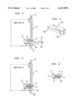
- FIG. 1 shows a prior art circuit pack inserted into a mounting rack with its insertion/extraction lever shoen in its stored position
- FIG. 1A shows a small molded part that is mounted on a circuit pack and is used to hold the insertion/locking lever in its stored position
- FIG. 1B shows an insertion/extraction lever
- FIG. 2 shows the prior art circuit pack with its insertion/extraction lever in use to extract the circuit pack from a mounting rack
- FIG. 3 is the same as FIG. 1 but shows the novel locking clip about to be inserted
- FIG. 4 is a three-dimensional view of the novel locking clip, showing it in greater detail
- FIG. 5 is the same as FIG. 1 but shows the novel locking clip fully inserted to prevent the use of the insertion/extraction lever to remove a circuit pack from a mounting rack;
- FIG. 6 is the same as FIG. 1 B but showing the novel locking clip inserted in the small molded part.
- FIGS. 1 and 2 are shown a prior art circuit pack 10 inserted into a prior art mounting rack.
- Very few details of the mounting rack are shown in these Figures because they are so well-known in the prior art, and so as not to detract from the presentation of the present invention.
- electrical connectors in the rear of a mounting rack are not shown
- top and bottom edge guides in which circuit packs are slid are not shown
- details of the front plate of the mounting rack are not shown.
- no circuitry is shown on the representative circuit packs, and no rear edge electrical connectors on the circuit packs are shown.
- FIGS. 1, 3 and 5 are shown as side cutaway views to better show how parts fit together and interact.
- lever 12 is shown having its main upper part 12, above a hole 22, and a lower part 12a below hole 22 appearing as two separate parts, but they are really one lever 12 as shown in FIGS. 1B and 2.
- FIG. 1 a simplified prior art circuit pack 10 with which the novel locking clip functions.
- On circuit pack 10 is typically mounted a number of electronic components (not shown).
- a circuit pack 10 is inserted into an open slot (not shown) of a mounting rack, and at the rear of each slot is an electrical connector (not shown) into which mating electrical connectors (not shown) on end 11 of circuit pack 10 are inserted in a mating engagement in a matter well-known in the art.
- the mounting rack (not shown) has a front surface 24 (shown only partially) through which circuit packs 10 are inserted into slots in the mounting rack, and with the edge of which the circuit pack levers cooperate to insert/extract the circuit packs 10. This insertion/extraction operation is described in greater detail further in this Detailed Description.
- Closure clip 13 Attached to circuit pack 10 is a closure clip 13 as shown.
- Closure clip 13 is also shown and described in greater detail with reference to FIG. 1B.
- Clip 13 is made of a durable, flexible material, such as nylon, and is used to hold a lever 12 in the position shown in FIG. 1. This is accomplished by a hook end 17 of closure clip 13 which extends through a hole 22 through lever 12 and catches the outer surface of lever 12 so that lever 12 cannot be lifted upward to extract circuit pack 10 from the mounting rack until hook end 17 is moved out of the way by an externally applied force F1.
- Closure clip 13 has two holes 14 there through that are used to fasten clip 13 to the edge of circuit pack 10 as shown using rivets (not shown).
- Lever 12 is rotatably fastened to circuit pack 10 by a pin 19.
- Lever 12 is shown and described in greater detail with reference to FIG. 1B.
- FIG. 1 there is a top portion 21 of lever 12 that is located outside of mounting rack front plate 24 when circuit pack 10 is fully inserted into the mounting rack.
- a downward force F1 is applied to hook end 17 of clip 13 to move flexible hook end 17 downward away from the edge of hole 22 through lever 12.
- lever 12 is released and an outward force can be applied to lower end 18 of lever 12 that will swing lever 12 outward and upward as shown in FIG. 2.
- lever 12 As lever 12 is rotated outward its upper element 21 pushes against the front of plate 24 of the mounting rack thereby creating a camming force which helps extract circuit pack 10 from the electrical connector in the rear of the mounting rack.
- lever 12 When circuit pack 10 is inserted into the mounting rack, lever 12 is first rotated outward as shown in FIG. 2. This provides clearance for upper element 20 of lever 12 to pass inside the mounting rack as circuit pack 10 is inserted and initially engages the electrical connector at the rear of the mounting rack.
- lever 12 As lever 12 is rotated downward its upper element 20 contacts the inner surface of front plate 24 of the mounting rack and thereby creates a camming force to fully seat the electrical contacts (not shown) on end 11 of circuit pack 10 into full engagement with mating electrical contacts (not shown) located at the rear of the mounting rack.
- Lever 12 is then rotated downward until it is locked by hook end 17 of closure clip 13 as shown a FIG. 1.
- FIG. 1A shows closure clip 13 by itself for ease of understanding.
- Clip 13 is made of a durable, flexible material, such as nylon because it has an arm 16 with locking hook 17 that must be capable of being flexed many times without breaking as circuit pack 10 is repeatedly inserted into and extracted from a mounting rack.
- Flexible arm 16 extends beyond the main portion of clip 13, as shown, so that it can extend through hole 22 through lever 12 as shown in FIGS. 1, 3 and 5.
- the top surface of locking hook 17 has a slanted surface which permits arm 16 to be deflected downward as lever 12 is lowered into its normally closed position, and locking hook 17 passes through hole 22 in lever 12. As locking hook 17 passes completely through hole 22, arm. 16 is able to move upward and hook 17 again catches the edge of hole 22 through lever 12 as shown in FIGS. 1, 3 and 5.
- FIG. 1B shows insertion/extraction lever 12 by itself.
- Lever 12 has a hole 19 that is used to rotatably fasten the lever to circuit pack 10 as shown in FIGS. 1, 2, 3 and 5, in a manner well-known and art.
- Lever 12 also includes upper end elements or extensions 20 and 21 which are respectively used to provide an insertion camming force and an extraction camming force to circuit pack 10 as previously described.
- Lever 12 also has a hole 22 through its lower end through which arm 16 of closure clip 13 passes when lever 12 is rotated into its normally closed position as shown in FIGS. 1, 3 and 5.
- FIG. 2 is the same as FIG. 1 except lever 12 has been released by depressing locking hook 17 of closure clip 13 downward, as previously described, until its locking hook 17 clears the top edge of hole 22, and lever 12 is shown swung part way outward and upward.
- upper element 21 of lever 12 is camming against the outer surface 24 of the mounting rack and is pulling circuit pack 10 in the direction of the arrow, out of the mounting rack until the circuit pack 10 edge connector (not shown) is disconnected from the mating connector (not shown) at the rear of the mounting rack. Circuit pack 10 is then manually withdrawn the remainder of the way from the mounting rack.
- lever 12 is first rotated outward as shown in FIG. 2.
- FIG. 3 is the same as FIG. 1, showing circuit pack 10 fully inserted into the mounting rack and lever 12 fully lowered to its normally closed position as has been previously described with reference to FIG. 1.
- space 15 under flexible arm 16 of closure clip 13 (described with reference to FIG. 1A) is in coaxial alignment with hole 22 through lever 12. It is into these two coaxially aligned spaces that the novel locking clip 23 of the present invention is inserted as indicated by the arrow adjacent to hole 22. Locking clip 23 is shown and described in detail with reference to FIG. 4 in the next paragraph.
- FIG. 4 shows an isometric view of locking clip 23 in accordance with the teaching of the preferred embodiment of the invention.
- Clip 23 has a forward portion 23A which has a tapered end 23B. Tapered end 23B aids in the insertion of locking clip 23 below arm 16 of closure clip 13 and into space 15 of closure clip 13.
- Locking clip 23 also has a rear portion 23C that is narrower than forward portion 23A to aid in removal of closure clip 13. However, rear portion 23C extends downward more than forward portion 23A and is used to set the maximum distance that locking clip 23 may travel into space 15 in closure clip 13.
- FIG. 5 is the same as FIG. 3 except locking clip 23 is shown fully inserted through hole 22 and into space 15 below arm 16 of closure clip 13.
- locking clip 23 When locking clip 23 is fully inserted, as shown in FIG. 5, it is very unobtrusive and is basically seen only by persons knowing where to look and knowing what to look for.
- rear end 23C of locking clip 23 prevents it traveling any further into space 15 below arm 16 than shown in FIG. 5.
- locking clip 23 When locking clip 23 is in place, as shown. it prevents a downward force on hook end 17 of arm 16 of closure clip 13 from deflecting arm 16 downward so that hook end 17 clears the upper edge of lever 12 and permits the lever to be rotated outward to extract circuit pack 10 from the mounting rack as previously described with reference to FIG. 2.
- a pair of tweezers, or similar small grasping tool must be used to reach in through the lower part of hole 22 through lever 12 and under arm 16 to grasp either side of rear portion 23C of locking clip 23. With the tweezers holding locking clip 23 it is extracted. With locking clip 23 extracted, lever 12 can again be released to remove circuit card 10 from the mounting rack as has been described with reference to FIG. 2.
- FIG. 6 shows only closure clip 13 with locking clip 23 inserted into space 15 below arm 16 for ease in understanding how locking clip 23 blocks any downward motion of arm 16 of closure clip 13. As described in the previous and other paragraphs this prevents any downward motion of hook end 17 from releasing lever 12 to rotate and extract circuit pack 10.
Abstract
Description
Claims (17)
Priority Applications (1)
| Application Number | Priority Date | Filing Date | Title |
|---|---|---|---|
| US09/257,846 US6147878A (en) | 1999-02-25 | 1999-02-25 | Secure latch locking clip |
Applications Claiming Priority (1)
| Application Number | Priority Date | Filing Date | Title |
|---|---|---|---|
| US09/257,846 US6147878A (en) | 1999-02-25 | 1999-02-25 | Secure latch locking clip |
Publications (1)
| Publication Number | Publication Date |
|---|---|
| US6147878A true US6147878A (en) | 2000-11-14 |
Family
ID=22978018
Family Applications (1)
| Application Number | Title | Priority Date | Filing Date |
|---|---|---|---|
| US09/257,846 Expired - Fee Related US6147878A (en) | 1999-02-25 | 1999-02-25 | Secure latch locking clip |
Country Status (1)
| Country | Link |
|---|---|
| US (1) | US6147878A (en) |
Cited By (14)
| Publication number | Priority date | Publication date | Assignee | Title |
|---|---|---|---|---|
| US20020089821A1 (en) * | 2000-11-10 | 2002-07-11 | Acard Technology Corporation | Automated disk-ejection apparatus and disk array having the same |
| US6483717B1 (en) * | 2000-05-02 | 2002-11-19 | Hewlett-Packard Company | Switch integral to a latch assembly |
| US20030031187A1 (en) * | 2001-08-10 | 2003-02-13 | Peter Heffernan | External storage for modular computer systems |
| GB2379092A (en) * | 2001-08-10 | 2003-02-26 | Sun Microsystems Inc | Ejection/injection lever for computer module |
| US6592195B2 (en) * | 2000-12-29 | 2003-07-15 | International Business Machines Corporation | Combination computer access cover and component removal tool |
| US20050220799A1 (en) * | 2001-12-12 | 2005-10-06 | Sitkovsky Michael V | Methods for using extracellular adenosine inhibitors and adenosine receptor inhibitors to enhance immune response and inflammation |
| US20060227520A1 (en) * | 2005-04-06 | 2006-10-12 | Lin-Wei Chang | Card retention device |
| US20070002550A1 (en) * | 2005-06-30 | 2007-01-04 | Dell Products L.P. | Component cam handle |
| US20070047180A1 (en) * | 2005-08-04 | 2007-03-01 | Wirtzberger Paul A | Electronic system having a release control and method |
| US20070095569A1 (en) * | 2005-10-28 | 2007-05-03 | International Business Machines Corporation | Enhanced blind-mated input/output card cassette packaging concept |
| US20120212923A1 (en) * | 2011-02-18 | 2012-08-23 | Hon Hai Precision Industry Co., Ltd. | Display unit having self-locking structure to fix display thereof |
| US20190206446A1 (en) * | 2016-11-15 | 2019-07-04 | Fujitsu Limited | Method for controlling information processing apparatus |
| US10383242B1 (en) * | 2018-11-21 | 2019-08-13 | Inventec (Pudong) Technology Corporation | Electronic device |
| WO2019195002A1 (en) * | 2018-04-03 | 2019-10-10 | Microsoft Technology Licensing, Llc | Locking mechanisms in separable and repairable devices |
Citations (6)
| Publication number | Priority date | Publication date | Assignee | Title |
|---|---|---|---|---|
| US4064551A (en) * | 1976-11-29 | 1977-12-20 | Northern Telecom Limited | Apparatus for insertion and withdrawal of printed circuit boards into and from mounting frames |
| US4301494A (en) * | 1979-09-28 | 1981-11-17 | Wescom, Inc. | Printed circuit board faceplate assembly |
| US4569001A (en) * | 1983-11-28 | 1986-02-04 | Northern Telecom Limited | Mounting for line cards on circuit boards in telecommunications apparatus |
| US5191970A (en) * | 1991-09-27 | 1993-03-09 | At&T Bell Laboratories | Apparatus for equipment unit protection switching |
| US5373133A (en) * | 1991-09-27 | 1994-12-13 | At&T Corp. | Equipment unit latch and associated switch |
| US5504456A (en) * | 1994-02-09 | 1996-04-02 | Psc, Inc. | Low noise wide band amplifier |
-
1999
- 1999-02-25 US US09/257,846 patent/US6147878A/en not_active Expired - Fee Related
Patent Citations (6)
| Publication number | Priority date | Publication date | Assignee | Title |
|---|---|---|---|---|
| US4064551A (en) * | 1976-11-29 | 1977-12-20 | Northern Telecom Limited | Apparatus for insertion and withdrawal of printed circuit boards into and from mounting frames |
| US4301494A (en) * | 1979-09-28 | 1981-11-17 | Wescom, Inc. | Printed circuit board faceplate assembly |
| US4569001A (en) * | 1983-11-28 | 1986-02-04 | Northern Telecom Limited | Mounting for line cards on circuit boards in telecommunications apparatus |
| US5191970A (en) * | 1991-09-27 | 1993-03-09 | At&T Bell Laboratories | Apparatus for equipment unit protection switching |
| US5373133A (en) * | 1991-09-27 | 1994-12-13 | At&T Corp. | Equipment unit latch and associated switch |
| US5504456A (en) * | 1994-02-09 | 1996-04-02 | Psc, Inc. | Low noise wide band amplifier |
Cited By (35)
| Publication number | Priority date | Publication date | Assignee | Title |
|---|---|---|---|---|
| US6483717B1 (en) * | 2000-05-02 | 2002-11-19 | Hewlett-Packard Company | Switch integral to a latch assembly |
| US20020089821A1 (en) * | 2000-11-10 | 2002-07-11 | Acard Technology Corporation | Automated disk-ejection apparatus and disk array having the same |
| US6836406B2 (en) * | 2000-11-10 | 2004-12-28 | Acard Technology Corporation | Automated disk-ejection apparatus and disk array having the same |
| US6592195B2 (en) * | 2000-12-29 | 2003-07-15 | International Business Machines Corporation | Combination computer access cover and component removal tool |
| US20030048614A1 (en) * | 2001-08-10 | 2003-03-13 | Garnett Paul J. | Removable media |
| GB2379092A (en) * | 2001-08-10 | 2003-02-26 | Sun Microsystems Inc | Ejection/injection lever for computer module |
| US20030030991A1 (en) * | 2001-08-10 | 2003-02-13 | Riddiford Martin P. | Support module ejection mechanism |
| US20030030993A1 (en) * | 2001-08-10 | 2003-02-13 | Kitchen James Robert | Module ejection mechanism |
| GB2379092B (en) * | 2001-08-10 | 2003-09-24 | Sun Microsystems Inc | Computer system module injection/ejection mechanism |
| US6762934B2 (en) | 2001-08-10 | 2004-07-13 | Sun Microsystems, Inc. | Module ejection mechanism |
| US20030031187A1 (en) * | 2001-08-10 | 2003-02-13 | Peter Heffernan | External storage for modular computer systems |
| US6912132B2 (en) * | 2001-08-10 | 2005-06-28 | Sun Microsystems, Inc. | Support module ejection mechanism |
| US7245632B2 (en) | 2001-08-10 | 2007-07-17 | Sun Microsystems, Inc. | External storage for modular computer systems |
| US6980427B2 (en) | 2001-08-10 | 2005-12-27 | Sun Microsystems, Inc. | Removable media |
| US20050220799A1 (en) * | 2001-12-12 | 2005-10-06 | Sitkovsky Michael V | Methods for using extracellular adenosine inhibitors and adenosine receptor inhibitors to enhance immune response and inflammation |
| US11471528B2 (en) | 2001-12-12 | 2022-10-18 | The Government of the United States of America as represented by the Secretary of the Department | Methods for using extracellular adenosine inhibitors and adenosine receptor inhibitors to enhance immune response and inflammation |
| US8716301B2 (en) | 2001-12-12 | 2014-05-06 | The United States Of America, As Represented By The Secretary, Department Of Health And Human Services | Methods for using extracellular adenosine inhibitors and adenosine receptor inhibitors to enhance immune response and inflammation |
| US10314908B2 (en) | 2001-12-12 | 2019-06-11 | The United States of America as represented by the Secretary of the Department of | Methods for using extracellular adenosine inhibitors and adenosine receptor inhibitors to enhance immune response and inflammation |
| US9415105B2 (en) | 2001-12-12 | 2016-08-16 | The United States Of America, As Represented By The Secretary, Department Of Health And Human Services | Methods for using extracellular adenosine inhibitors and adenosine receptor inhibitors to enhance immune response and inflammation |
| US8080554B2 (en) * | 2001-12-12 | 2011-12-20 | The United States Of America As Represented By The Secretary Of The Department Of Health And Human Services | Methods for using extracellular adenosine inhibitors and adenosine receptor inhibitors to enhance immune response and inflammation |
| US20060227520A1 (en) * | 2005-04-06 | 2006-10-12 | Lin-Wei Chang | Card retention device |
| US7209365B2 (en) * | 2005-04-06 | 2007-04-24 | Inventec Corporation | Card retention device |
| US20070002550A1 (en) * | 2005-06-30 | 2007-01-04 | Dell Products L.P. | Component cam handle |
| US7295447B2 (en) * | 2005-06-30 | 2007-11-13 | Dell Products L.P. | Component cam handle |
| US20070047180A1 (en) * | 2005-08-04 | 2007-03-01 | Wirtzberger Paul A | Electronic system having a release control and method |
| US7791865B2 (en) * | 2005-08-04 | 2010-09-07 | Hewlett-Packard Development Company, L.P. | Electronic system having a release control and method |
| US7378603B2 (en) * | 2005-10-28 | 2008-05-27 | International Business Machines Corporation | Enhanced blind-mated input/output card cassette packaging concept |
| US20070095569A1 (en) * | 2005-10-28 | 2007-05-03 | International Business Machines Corporation | Enhanced blind-mated input/output card cassette packaging concept |
| US20120212923A1 (en) * | 2011-02-18 | 2012-08-23 | Hon Hai Precision Industry Co., Ltd. | Display unit having self-locking structure to fix display thereof |
| US20190206446A1 (en) * | 2016-11-15 | 2019-07-04 | Fujitsu Limited | Method for controlling information processing apparatus |
| US10424344B2 (en) * | 2016-11-15 | 2019-09-24 | Fujitsu Limited | Method of controlling information processing apparatus |
| US10482926B2 (en) | 2016-11-15 | 2019-11-19 | Fujitsu Limited | Information processing apparatus |
| WO2019195002A1 (en) * | 2018-04-03 | 2019-10-10 | Microsoft Technology Licensing, Llc | Locking mechanisms in separable and repairable devices |
| US11419228B2 (en) | 2018-04-03 | 2022-08-16 | Microsoft Technology Licensing, Llc | Locking mechanisms in separable and repairable devices |
| US10383242B1 (en) * | 2018-11-21 | 2019-08-13 | Inventec (Pudong) Technology Corporation | Electronic device |
Similar Documents
| Publication | Publication Date | Title |
|---|---|---|
| US6147878A (en) | Secure latch locking clip | |
| US6129572A (en) | Electrical connector with latch to retain IC card | |
| US6185106B1 (en) | Printed circuit board extractor tool operated latch | |
| US6185103B1 (en) | Releasable disk drive for electronic devices | |
| US4975073A (en) | Insertion and extraction aid for printed circuit card | |
| US5428507A (en) | Front panels for rack-mounted printed circuit boards | |
| US6203076B1 (en) | Fold-down handle device | |
| JPS60244720A (en) | Paper storing equipment | |
| EP3591770B1 (en) | Network port cover module and network port locking device having same | |
| CA2251590C (en) | Reduced-encumbrance anti-theft case, particularly for compact disks, musicassettes, videocassettes and the like | |
| US20150159412A1 (en) | Self-locking inject/eject latch | |
| US3228740A (en) | Modular drawer handle | |
| WO2001031152A1 (en) | Opener for a magnetic latch in an anti-theft device for cassettes | |
| US6680851B1 (en) | Positive latching combination handle and insertion/removal tool method and apparatus | |
| KR100500242B1 (en) | Locking apparatus for battery pack | |
| JP2720690B2 (en) | Circuit board attachment / detachment mechanism | |
| US11412634B2 (en) | Self-locking and foldable ejector arm | |
| JP3361486B2 (en) | Product display case locking device and its unlocking device | |
| JPH04268686A (en) | Ic card extraction mechanism | |
| JP2751482B2 (en) | Equipment for testing printed circuit boards | |
| JP2663958B2 (en) | Insertion / extraction mechanism for electronic circuit package | |
| JP2003288549A (en) | Drawing-out tool for compact flash card | |
| CA1260239A (en) | Extractor tool for printed circuit cards | |
| KR100452724B1 (en) | carrier device of hard disk drive | |
| JPS61259600A (en) | Insertion and withdrawal of package |
Legal Events
| Date | Code | Title | Description |
|---|---|---|---|
| AS | Assignment |
Owner name: LUCENT TECHNOLOGIES, INC., NEW JERSEY Free format text: ASSIGNMENT OF ASSIGNORS INTEREST;ASSIGNOR:HESELTON, DONALD E.;REEL/FRAME:009802/0736 Effective date: 19990224 |
|
| FEPP | Fee payment procedure |
Free format text: PAYOR NUMBER ASSIGNED (ORIGINAL EVENT CODE: ASPN); ENTITY STATUS OF PATENT OWNER: LARGE ENTITY |
|
| AS | Assignment |
Owner name: THE CHASE MANHATTAN BANK, AS COLLATERAL AGENT, TEX Free format text: CONDITIONAL ASSIGNMENT OF AND SECURITY INTEREST IN PATENT RIGHTS;ASSIGNOR:LUCENT TECHNOLOGIES INC. (DE CORPORATION);REEL/FRAME:011722/0048 Effective date: 20010222 |
|
| REMI | Maintenance fee reminder mailed | ||
| LAPS | Lapse for failure to pay maintenance fees | ||
| STCH | Information on status: patent discontinuation |
Free format text: PATENT EXPIRED DUE TO NONPAYMENT OF MAINTENANCE FEES UNDER 37 CFR 1.362 |
|
| FP | Lapsed due to failure to pay maintenance fee |
Effective date: 20041114 |
|
| AS | Assignment |
Owner name: LUCENT TECHNOLOGIES INC., NEW JERSEY Free format text: TERMINATION AND RELEASE OF SECURITY INTEREST IN PATENT RIGHTS;ASSIGNOR:JPMORGAN CHASE BANK, N.A. (FORMERLY KNOWN AS THE CHASE MANHATTAN BANK), AS ADMINISTRATIVE AGENT;REEL/FRAME:018590/0287 Effective date: 20061130 |