US6148250A - Altitude detection by use of planar approximation of a region of ground surface - Google Patents
Altitude detection by use of planar approximation of a region of ground surface Download PDFInfo
- Publication number
- US6148250A US6148250A US09/246,456 US24645699A US6148250A US 6148250 A US6148250 A US 6148250A US 24645699 A US24645699 A US 24645699A US 6148250 A US6148250 A US 6148250A
- Authority
- US
- United States
- Prior art keywords
- altitude
- ground surface
- flying object
- regions
- distance
- Prior art date
- Legal status (The legal status is an assumption and is not a legal conclusion. Google has not performed a legal analysis and makes no representation as to the accuracy of the status listed.)
- Expired - Fee Related
Links
Images
Classifications
-
- G—PHYSICS
- G01—MEASURING; TESTING
- G01C—MEASURING DISTANCES, LEVELS OR BEARINGS; SURVEYING; NAVIGATION; GYROSCOPIC INSTRUMENTS; PHOTOGRAMMETRY OR VIDEOGRAMMETRY
- G01C11/00—Photogrammetry or videogrammetry, e.g. stereogrammetry; Photographic surveying
- G01C11/04—Interpretation of pictures
- G01C11/06—Interpretation of pictures by comparison of two or more pictures of the same area
-
- G—PHYSICS
- G01—MEASURING; TESTING
- G01C—MEASURING DISTANCES, LEVELS OR BEARINGS; SURVEYING; NAVIGATION; GYROSCOPIC INSTRUMENTS; PHOTOGRAMMETRY OR VIDEOGRAMMETRY
- G01C5/00—Measuring height; Measuring distances transverse to line of sight; Levelling between separated points; Surveyors' levels
- G01C5/005—Measuring height; Measuring distances transverse to line of sight; Levelling between separated points; Surveyors' levels altimeters for aircraft
-
- G—PHYSICS
- G06—COMPUTING; CALCULATING OR COUNTING
- G06T—IMAGE DATA PROCESSING OR GENERATION, IN GENERAL
- G06T7/00—Image analysis
- G06T7/70—Determining position or orientation of objects or cameras
-
- H—ELECTRICITY
- H04—ELECTRIC COMMUNICATION TECHNIQUE
- H04N—PICTORIAL COMMUNICATION, e.g. TELEVISION
- H04N13/00—Stereoscopic video systems; Multi-view video systems; Details thereof
- H04N13/20—Image signal generators
- H04N13/204—Image signal generators using stereoscopic image cameras
- H04N13/239—Image signal generators using stereoscopic image cameras using two 2D image sensors having a relative position equal to or related to the interocular distance
-
- G—PHYSICS
- G06—COMPUTING; CALCULATING OR COUNTING
- G06T—IMAGE DATA PROCESSING OR GENERATION, IN GENERAL
- G06T2207/00—Indexing scheme for image analysis or image enhancement
- G06T2207/10—Image acquisition modality
- G06T2207/10004—Still image; Photographic image
- G06T2207/10012—Stereo images
-
- H—ELECTRICITY
- H04—ELECTRIC COMMUNICATION TECHNIQUE
- H04N—PICTORIAL COMMUNICATION, e.g. TELEVISION
- H04N13/00—Stereoscopic video systems; Multi-view video systems; Details thereof
- H04N13/10—Processing, recording or transmission of stereoscopic or multi-view image signals
-
- H—ELECTRICITY
- H04—ELECTRIC COMMUNICATION TECHNIQUE
- H04N—PICTORIAL COMMUNICATION, e.g. TELEVISION
- H04N13/00—Stereoscopic video systems; Multi-view video systems; Details thereof
- H04N13/10—Processing, recording or transmission of stereoscopic or multi-view image signals
- H04N13/189—Recording image signals; Reproducing recorded image signals
-
- H—ELECTRICITY
- H04—ELECTRIC COMMUNICATION TECHNIQUE
- H04N—PICTORIAL COMMUNICATION, e.g. TELEVISION
- H04N13/00—Stereoscopic video systems; Multi-view video systems; Details thereof
- H04N13/20—Image signal generators
- H04N13/204—Image signal generators using stereoscopic image cameras
- H04N13/207—Image signal generators using stereoscopic image cameras using a single 2D image sensor
- H04N13/221—Image signal generators using stereoscopic image cameras using a single 2D image sensor using the relative movement between cameras and objects
-
- H—ELECTRICITY
- H04—ELECTRIC COMMUNICATION TECHNIQUE
- H04N—PICTORIAL COMMUNICATION, e.g. TELEVISION
- H04N13/00—Stereoscopic video systems; Multi-view video systems; Details thereof
- H04N13/20—Image signal generators
- H04N13/296—Synchronisation thereof; Control thereof
-
- H—ELECTRICITY
- H04—ELECTRIC COMMUNICATION TECHNIQUE
- H04N—PICTORIAL COMMUNICATION, e.g. TELEVISION
- H04N13/00—Stereoscopic video systems; Multi-view video systems; Details thereof
- H04N2013/0074—Stereoscopic image analysis
- H04N2013/0081—Depth or disparity estimation from stereoscopic image signals
Definitions
- the present invention relates to an altitude detecting apparatus for a flying object and more particularly to an altitude detecting apparatus for a flying object flying at a relatively low altitude.
- an altimeter is an essential apparatus.
- a technique as spraying agricultural chemical by means of an unmanned helicopter has come into a stage of practical use.
- a remote control in which an operator employs a radio-control of the helicopter by visual observation
- the other is an autonomous control in which the helicopter flies or makes a landing and the like autonomously without the help of an operator.
- the primary object of using the unmanned helicopter is to save labor, it is desirable that the unmanned helicopter is autonomously controlled without the help of a skilled operator. Therefore, for this type of unmanned helicopter, an altimeter offering high precision altitude data is indispensable.
- altimeters such as an altimeter in which an altitude is obtained by transforming the difference of atmospheric pressure into altitude, an altimeter in which an altitude is calculated from a reflecting time when laser beam, radio wave, supersonic wave and like is transmitted to the ground surface, an altimeter in which an altitude is found based on positional information transmitted from positioning satellites such as D-GPS, an altimeter in which an altitude is obtained from acceleration and other kinds.
- these altimeters Taking a measuring accuracy of ground altitude, a reflecting characteristic of object on ground, an environment under which the altimeter is used and the like into consideration, these altimeters have merits and demerits respectively. Few altimeters satisfy conditions suitable to an altimeter for a flying object flying at low altitude.
- an object of the present invention to provide an altitude detecting apparatus capable of accurately detecting an altitude of a flying object without relying upon information to know an actual moving distance or information difficult to measure, such as an angle of depression.
- the present invention comprises a pair of stereoscopic cameras mounted on said flying object for taking a stereoscopic image of a ground surface under the flying object, a stereoscopic processing section for processing a pair of images imaged by the cameras and for calculating a distance data of the ground surface, and an altitude calculating section for creating a configuration of the ground surface based on the distance data of a plurality of measuring points on the ground surface so as to calculate an altitude of the flying object to the ground surface.
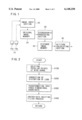
- FIG. 1 is a schematic block diagram of an altitude detecting apparatus according to the present invention
- FIG. 2 is a flowchart showing a flow of control of a process for deleting peculiar points
- FIG. 3 is a flowchart showing a flow of control of a process for calculating an altitude
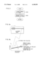
- FIG. 4a is an explanatory view showing a distance image on a coordinate having a horizontal axis i and a vertical axis j;
- FIG. 4b is an explanatory view showing a series of distance data expressed on a real space coordinate having a horizontal axis X showing a horizontal position and a longitudinal axis Z showing a distance.
- FIG. 1 shows a construction of an altitude detecting apparatus mounted on a flying object such as a helicopter which flies at a relatively low altitude.
- the apparatus comprises a pair of stereoscopic cameras 10 for taking three-dimensional image of a scenery below the flying object, an image input section 20 for making an input process of the image taken by the cameras 10, an original image memory 25 for storing an image processed in the image input section 20 as an original image, a stereoscopic processing section 30 for producing distance distribution information (distance image) from the original image by a stereo-matching, a distance image memory 35 for storing the distance image, and an altitude calculating section 40 for calculating a ground altitude from distance information of a plurality of detecting points.
- the foregoing parts, hereinafter, will be explained in more detail.
- the stereoscopic cameras 10 are two CCD cameras 10a, 10b which operate synchronously with each other and whose shutter speeds are variably controlled.
- One CCD camera 10a is used as a primary camera for imaging a reference image and the other CCD camera 10b is used as a subsidiary camera for imaging a comparison image. Further, these two cameras are disposed with a specified base length and their optical axes are arranged in parallel with each other.
- the image input section 20 comprises an analogue interface having a gain control amplifier, an A/D converter for converting analogue data from the CCD cameras 10a, 10b into digital image data and a high integrated FPGA (Flexible Programmable Gate Array) having miscellaneous image processing functions such as a LOG conversion table to make a logarithmic conversion with respect to bright and shadow portions of image. That is to say, in the image input section 20, after inputting image signals from the CCD cameras 10a, 10b in order by a gain adjustment, image corrections such as improving contrasts of low brightness portions by the LOG conversion are performed and then thus corrected image signals are converted into digital image data having a given brightness. After that, those image signals are sent to the original image memory 25 for storing.
- FPGA Flexible Programmable Gate Array
- the stereoscopic processing section 30 is constituted of a high integrated FPGA containing a city-block distance calculating circuit, a deviation detecting circuit and the like. With respect to two images stored in the original image memory 25, the reference image and the comparison image, the stereo matching is performed for each small region of respective two images to obtain three-dimensional image information (distance images) expressed in numbers.
- a city-block distance between a small region of the reference image and a corresponding small region of the comparison image is calculated and then in the deviation detecting circuit, it is checked whether or not these two small regions agree by evaluating minimum and maximum values of the calculated city-block distance. If this checking condition is satisfied and the city-block distance becomes minimum, the deviation amount of picture element at this moment is a distance information of the subject small region of the reference image. Thus obtained distance information is stored in the distance image memory 35.
- Detailed processes of the stereo matching are described in Japanese Patent Application Laid-open No. Toku-Kai-Hei 5-114099 filed by the applicant of the present invention.
- the altitude calculating section 40 is constituted of an RISC processor and the like.
- the RISC (Reduced Instrumentation Set Computer) processor performs a recognition process at high speeds based on the distance distribution information obtained from the distance image. That is, in the altitude calculating section 40, assuming a plane or a curved surface from distance information of many points on the ground, the length of a perpendicular line from the flying object to the plane or the curved surface is defined to be a ground altitude. In this embodiment, the ground surface is detected as a plane from the distance information of multiple points on the ground and the length of a perpendicular line from the flying object down to that plane is obtained as a ground altitude. In order to speed up the calculation, the processes are substantially simplified.
- a step S100 the distance image is read and peculiar points whose values are largely apart from the value of maximum frequency are deleted from the overall distance image.
- the process at this step S100 is a preprocess for securing an uneven-data deleting filter process which will be described hereinafter at a step S400.
- this distance image is divided into small regions or blocks having a distance data (deviation amount of picture element), each of which is composed of 8 (laterally) ⁇ 4 (longitudinally) picture elements.
- this distance image is divided into 25 medium regions each of which is composed of 80 (laterally) ⁇ 40 (longitudinally) picture elements. Respective medium regions include 100 (10 ⁇ 10) small regions and a histogram of deviation amount is prepared for these respective medium regions.
- a histogram of deviation amount is prepared for these respective medium regions.
- the program goes to a step S200 where a plurality of sampled regions are selected in the distance image and the position of the sampled regions on the image surface is corrected to the position having no distortion of a lens.
- a plurality of sampled regions are selected in the distance image and the position of the sampled regions on the image surface is corrected to the position having no distortion of a lens.
- 357 blocks of small region composed of 8 (laterally) ⁇ 4 (longitudinally) are selected from the image, that is, laterally 21 blocks for every 16 picture elements and longitudinally 17 blocks for every 8 picture elements.
- a distance R between the position of the distance image and a point of intersection of the optical axis and the image surface is corrected according to a correction value D expressed in the following formula (1).
- A, B and C are correction coefficients determined by lens manufactures or by experiments.
- a three-dimensional coordinate of respective sampled small regions in the real space is obtained from the corrected position and the distance data of each sampled region on the CCD surface.
- an uneven-plane deleting filter process for deleting picture elements not constituting the plane from the distance image is performed. In this process, as shown in FIGS. 4a and 4b, taking a note of a line on the image coordinate (i axis laterally, j axis vertically), a series of data is obtained on the real space coordinate (X axis laterally, Z axis longitudinally).
- this series of data is approximated to a linear equation according to the least square method, as shown in FIG. 4b.
- only data within a specified range (shown by slashes) are used for obtaining a plane and data out of the specified range are deleted. This process is repeated by scanning from top to bottom to delete the distance information not constituting a plane as peculiar points from the distance image.
- an altitude calculating process is performed as shown in a flowchart of FIG. 3.
- an equation of plane as shown in the following equation (2) is established based on groups of data of coordinates (X, Y, Z) transformed from the image space into the real space by use of the least square method.
- the program goes to a step S600 where the length h of the perpendicular line from the camera to the plane is obtained according to the following formula (3).
- This length h is a ground altitude.
Landscapes
- Engineering & Computer Science (AREA)
- Physics & Mathematics (AREA)
- General Physics & Mathematics (AREA)
- Multimedia (AREA)
- Radar, Positioning & Navigation (AREA)
- Remote Sensing (AREA)
- Signal Processing (AREA)
- Computer Vision & Pattern Recognition (AREA)
- Theoretical Computer Science (AREA)
- Image Processing (AREA)
- Measurement Of Optical Distance (AREA)
- Image Analysis (AREA)
- Length Measuring Devices By Optical Means (AREA)
Abstract
A three-dimensional image of a ground surface taken by a stereoscopic camera is converted to a distance image in a stereoscopic processing section. In an altitude calculating section, after peculiar points contained in the distance image are deleted and further the lens distortion is deleted from the distance image, the distance image is transferred to a real space coordinate. Then, an equation approximating to a plane is obtained from data of the distance image and a length of a perpendicular line to the plane is calculated as a ground altitude.
Description
1. Field of the Invention
The present invention relates to an altitude detecting apparatus for a flying object and more particularly to an altitude detecting apparatus for a flying object flying at a relatively low altitude.
2. Prior Arts
When a flying object flies at a low altitude, or when it makes a take off or a landing, an altimeter is an essential apparatus. In recent years, such a technique as spraying agricultural chemical by means of an unmanned helicopter has come into a stage of practical use. In this case, there are two ways in controlling the unmanned helicopter. One is a remote control in which an operator employs a radio-control of the helicopter by visual observation and the other is an autonomous control in which the helicopter flies or makes a landing and the like autonomously without the help of an operator. In the former case, it needs a high skill to continue to monitor an altitude of the helicopter by eye observation or to make a landing safely from a remote place. Further, since the primary object of using the unmanned helicopter is to save labor, it is desirable that the unmanned helicopter is autonomously controlled without the help of a skilled operator. Therefore, for this type of unmanned helicopter, an altimeter offering high precision altitude data is indispensable.
There are many kinds of altimeters such as an altimeter in which an altitude is obtained by transforming the difference of atmospheric pressure into altitude, an altimeter in which an altitude is calculated from a reflecting time when laser beam, radio wave, supersonic wave and like is transmitted to the ground surface, an altimeter in which an altitude is found based on positional information transmitted from positioning satellites such as D-GPS, an altimeter in which an altitude is obtained from acceleration and other kinds. Taking a measuring accuracy of ground altitude, a reflecting characteristic of object on ground, an environment under which the altimeter is used and the like into consideration, these altimeters have merits and demerits respectively. Few altimeters satisfy conditions suitable to an altimeter for a flying object flying at low altitude.
In order to satisfy such conditions, it is particularly important that the altimeter is free from the reflecting characteristic of an object on ground. With these in mind, a technique in which an altitude is measured by processing images taken by cameras from the flying object, is most promising. As an example of a technique of detecting altitude by images, there is a prior art disclosed in Japanese Patent Application No. Toku-Kai-Shou 62-88914. In this prior art, an altitude is obtained based on the comparison of the movement of an object in an image area with an actual distance to that area.
However, according to this prior art of measuring altitude based on image, since the actual distance to the area must be known, a map including the imaged area is needed and also a specified mark must be imaged in the area. Further, an angle of depression with respect to the center of field of view must be known and this angle of depression is measured indirectly by a gyro compass and the like, thereby the measuring accuracy is exacerbated.
In view of the defects of the prior arts, it is an object of the present invention to provide an altitude detecting apparatus capable of accurately detecting an altitude of a flying object without relying upon information to know an actual moving distance or information difficult to measure, such as an angle of depression.
To achieve the object, the present invention comprises a pair of stereoscopic cameras mounted on said flying object for taking a stereoscopic image of a ground surface under the flying object, a stereoscopic processing section for processing a pair of images imaged by the cameras and for calculating a distance data of the ground surface, and an altitude calculating section for creating a configuration of the ground surface based on the distance data of a plurality of measuring points on the ground surface so as to calculate an altitude of the flying object to the ground surface.
FIG. 1 is a schematic block diagram of an altitude detecting apparatus according to the present invention;
FIG. 2 is a flowchart showing a flow of control of a process for deleting peculiar points;
FIG. 3 is a flowchart showing a flow of control of a process for calculating an altitude;
FIG. 4a is an explanatory view showing a distance image on a coordinate having a horizontal axis i and a vertical axis j; and
FIG. 4b is an explanatory view showing a series of distance data expressed on a real space coordinate having a horizontal axis X showing a horizontal position and a longitudinal axis Z showing a distance.
Reference will hereinafter be made to the accompanying drawings in order to facilitate understanding of the present invention.
FIG. 1 shows a construction of an altitude detecting apparatus mounted on a flying object such as a helicopter which flies at a relatively low altitude. The apparatus comprises a pair of stereoscopic cameras 10 for taking three-dimensional image of a scenery below the flying object, an image input section 20 for making an input process of the image taken by the cameras 10, an original image memory 25 for storing an image processed in the image input section 20 as an original image, a stereoscopic processing section 30 for producing distance distribution information (distance image) from the original image by a stereo-matching, a distance image memory 35 for storing the distance image, and an altitude calculating section 40 for calculating a ground altitude from distance information of a plurality of detecting points. The foregoing parts, hereinafter, will be explained in more detail.
The stereoscopic cameras 10 are two CCD cameras 10a, 10b which operate synchronously with each other and whose shutter speeds are variably controlled. One CCD camera 10a is used as a primary camera for imaging a reference image and the other CCD camera 10b is used as a subsidiary camera for imaging a comparison image. Further, these two cameras are disposed with a specified base length and their optical axes are arranged in parallel with each other.
The image input section 20 comprises an analogue interface having a gain control amplifier, an A/D converter for converting analogue data from the CCD cameras 10a, 10b into digital image data and a high integrated FPGA (Flexible Programmable Gate Array) having miscellaneous image processing functions such as a LOG conversion table to make a logarithmic conversion with respect to bright and shadow portions of image. That is to say, in the image input section 20, after inputting image signals from the CCD cameras 10a, 10b in order by a gain adjustment, image corrections such as improving contrasts of low brightness portions by the LOG conversion are performed and then thus corrected image signals are converted into digital image data having a given brightness. After that, those image signals are sent to the original image memory 25 for storing.
The stereoscopic processing section 30 is constituted of a high integrated FPGA containing a city-block distance calculating circuit, a deviation detecting circuit and the like. With respect to two images stored in the original image memory 25, the reference image and the comparison image, the stereo matching is performed for each small region of respective two images to obtain three-dimensional image information (distance images) expressed in numbers.
That is, in the city-block distance calculating circuit, a city-block distance between a small region of the reference image and a corresponding small region of the comparison image is calculated and then in the deviation detecting circuit, it is checked whether or not these two small regions agree by evaluating minimum and maximum values of the calculated city-block distance. If this checking condition is satisfied and the city-block distance becomes minimum, the deviation amount of picture element at this moment is a distance information of the subject small region of the reference image. Thus obtained distance information is stored in the distance image memory 35. Detailed processes of the stereo matching are described in Japanese Patent Application Laid-open No. Toku-Kai-Hei 5-114099 filed by the applicant of the present invention.
The altitude calculating section 40 is constituted of an RISC processor and the like. The RISC (Reduced Instrumentation Set Computer) processor performs a recognition process at high speeds based on the distance distribution information obtained from the distance image. That is, in the altitude calculating section 40, assuming a plane or a curved surface from distance information of many points on the ground, the length of a perpendicular line from the flying object to the plane or the curved surface is defined to be a ground altitude. In this embodiment, the ground surface is detected as a plane from the distance information of multiple points on the ground and the length of a perpendicular line from the flying object down to that plane is obtained as a ground altitude. In order to speed up the calculation, the processes are substantially simplified.
Further, since the distances to multiple points in the image are measured and these distance information is used for calculation, not only a plane but also an up-and-down surface, a stairs-like terrain or the like, can be recognized over the wide range with good accuracy.
Next, a process of calculating an altitude in the altitude calculating section 40 will be described with reference to flowcharts shown in FIGS. 2 and 3.
Generally, in case where the ground surface is detected as a plane from the distance information of multiple points, if distance information not constituting the plane is contained therein, this information has a large effect on the detection of altitude. In case where noises or projection-like objects are detected, these noises or objects are expressed as peculiar points having apparently different values from other coherent points. Therefore, according to the process of deleting peculiar points in this embodiment, first these peculiar points are deleted from the distance image and further when the coordinate system is transformed from the image space to the actual space, the distance data belonging to different series of distance data are deleted. Using the distance data from which the peculiar points are deleted, a plane is created from the distance data of multiple points in the real space coordinate system.
Specifically, in the flowchart shown in FIG. 2, at a step S100 the distance image is read and peculiar points whose values are largely apart from the value of maximum frequency are deleted from the overall distance image. The process at this step S100 is a preprocess for securing an uneven-data deleting filter process which will be described hereinafter at a step S400. In case of the distance image having a picture size composed of 400 (laterally) ×200 (longitudinally) picture elements, for example this distance image is divided into small regions or blocks having a distance data (deviation amount of picture element), each of which is composed of 8 (laterally)×4 (longitudinally) picture elements. Furthermore, this distance image is divided into 25 medium regions each of which is composed of 80 (laterally)×40 (longitudinally) picture elements. Respective medium regions include 100 (10×10) small regions and a histogram of deviation amount is prepared for these respective medium regions. When compared with the distance data having a maximum frequency in this histogram, if the distance data exceed a specified range (±1 of the distance data of the maximum frequency), the deviation amount of the block is let null to delete this peculiar point.
Then, the program goes to a step S200 where a plurality of sampled regions are selected in the distance image and the position of the sampled regions on the image surface is corrected to the position having no distortion of a lens. For example, 357 blocks of small region composed of 8 (laterally)×4 (longitudinally) are selected from the image, that is, laterally 21 blocks for every 16 picture elements and longitudinally 17 blocks for every 8 picture elements. A distance R between the position of the distance image and a point of intersection of the optical axis and the image surface is corrected according to a correction value D expressed in the following formula (1).
D=A·R.sup.5 +B·R.sup.3 +C·R (1)
where A, B and C are correction coefficients determined by lens manufactures or by experiments.
Then, at a step S300 a three-dimensional coordinate of respective sampled small regions in the real space is obtained from the corrected position and the distance data of each sampled region on the CCD surface. Further, at a step S400 an uneven-plane deleting filter process for deleting picture elements not constituting the plane from the distance image is performed. In this process, as shown in FIGS. 4a and 4b, taking a note of a line on the image coordinate (i axis laterally, j axis vertically), a series of data is obtained on the real space coordinate (X axis laterally, Z axis longitudinally).
Then, this series of data is approximated to a linear equation according to the least square method, as shown in FIG. 4b. At this time, only data within a specified range (shown by slashes) are used for obtaining a plane and data out of the specified range are deleted. This process is repeated by scanning from top to bottom to delete the distance information not constituting a plane as peculiar points from the distance image.
Then, after deleting the irrespective distance information, an altitude calculating process is performed as shown in a flowchart of FIG. 3. First, at a step S500 an equation of plane as shown in the following equation (2) is established based on groups of data of coordinates (X, Y, Z) transformed from the image space into the real space by use of the least square method.
ax+by+cz=1 (2)
Next, solving the matric equations, respective coefficients a, b and c are obtained.
Then, the program goes to a step S600 where the length h of the perpendicular line from the camera to the plane is obtained according to the following formula (3). This length h is a ground altitude.
h=1/(a.sup.2 +b.sup.2 +c.sup.2).sup.1/2 (3).
While the presently preferred embodiment of the present invention has been shown and described, it is to be understood that this disclosure is for the purpose of illustration and that various changes and modifications may be made without departing from the scope of the invention as set forth in the appended claims.
Claims (5)
1. An altitude detecting apparatus for detecting an altitude of a flying object, comprising:
a pair of stereoscopic cameras mounted on said flying object for taking a stereoscopic image of a ground surface under said flying object;
a stereoscopic processing section for processing a pair of images by said cameras and for calculating a distance data of said ground surface; and
an altitude calculating section for creating a configuration of said ground surface based on said distance data of a plurality of measuring points on said ground surface so as to calculate an altitude of said flying object to said ground surface;
wherein said stereoscopic processing section obtains distance data over a succession of regions of the ground surface, each of said regions being characterized by lateral and longitudinal coordinates identifying points of the data associated with movement of the flying object; and
said altitude calculating section is operative to characterize the data of distance between the flying object and the ground surface by a best-fit plane for each of said regions, the altitude being calculated along a line from the object to the plane for each of the succession of said regions of the around surface.
2. The apparatus according to claim 1, further comprising:
a correcting means for correcting a distortion of lenses of said cameras so as to make said distance data more accurate, said correcting means being operative to adjust locations of points of the data on said plane by a mathematical formulation employing a set of correction coefficients.
3. The apparatus according to claim 1, wherein said altitude calculating section calculates a length of said line as a perpendicular line to said plane in a respective one of said regions as an altitude of said flying object to said ground surface.
4. The apparatus according to claim 3, further comprising:
a distance data deleting means for approximating a series of said distance data to a straight line, and for deleting a portion of said distance data falling outside of a specified range established around said straight line and being regarded as not constituting a part of said plane.
5. A method, employing an altitude detecting apparatus, for detecting an altitude of a flying object, comprising steps of:
mounting a pair of stereoscopic cameras on said flying object for taking a stereoscopic image of a ground surface under said flying object;
processing, by means of a stereoscopic processing section, a pair of images produced by said cameras, and calculating distance data of said ground surface from said flying object;
creating, by means of an altitude calculating section, a configuration of said ground surface based on said distance data of a plurality of measuring points on said ground surface;
calculating, by use of said measuring points, an altitude of said flying object relative to said ground surface;
wherein said processing step includes obtaining distance data over a succession of regions of the ground surface, each of said regions being characterized by lateral and longitudinal coordinates identifying points of the data associated with movement of the flying object; and
said calculating step includes characterizing the data of distance between the flying object and the ground surface by a best-fit plane for each of said regions, the altitude being calculated along a line from the object to the plane for each of the succession of said regions of the ground surface.
Applications Claiming Priority (2)
| Application Number | Priority Date | Filing Date | Title |
|---|---|---|---|
| JP03623298A JP3850541B2 (en) | 1998-02-18 | 1998-02-18 | Advanced measuring device |
| JP10-036232 | 1998-02-18 |
Publications (1)
| Publication Number | Publication Date |
|---|---|
| US6148250A true US6148250A (en) | 2000-11-14 |
Family
ID=12464040
Family Applications (1)
| Application Number | Title | Priority Date | Filing Date |
|---|---|---|---|
| US09/246,456 Expired - Fee Related US6148250A (en) | 1998-02-18 | 1999-02-09 | Altitude detection by use of planar approximation of a region of ground surface |
Country Status (4)
| Country | Link |
|---|---|
| US (1) | US6148250A (en) |
| EP (1) | EP0937963B1 (en) |
| JP (1) | JP3850541B2 (en) |
| DE (1) | DE69925057T2 (en) |
Cited By (11)
| Publication number | Priority date | Publication date | Assignee | Title |
|---|---|---|---|---|
| US20010055063A1 (en) * | 2000-05-26 | 2001-12-27 | Honda Giken Kogyo Kabushiki Kaisha | Position detection apparatus, position detection method and position detection program |
| US6694228B2 (en) | 2002-05-09 | 2004-02-17 | Sikorsky Aircraft Corporation | Control system for remotely operated vehicles for operational payload employment |
| US6714663B1 (en) * | 1999-11-09 | 2004-03-30 | Lockheed Martin Corp. | Method and software-implemented apparatus for ground plane estimation in multi-dimensional data |
| CN101493325B (en) * | 2009-03-09 | 2010-11-10 | 清华大学 | Laser mapping system |
| US20130151040A1 (en) * | 2011-05-21 | 2013-06-13 | Christopher T. Allen | Low-altitude altimeter and method |
| US20130215234A1 (en) * | 2012-02-16 | 2013-08-22 | Electronics And Telecommunications Research Institute | Method and apparatus for stereo matching |
| CN105606073A (en) * | 2016-01-11 | 2016-05-25 | 谭圆圆 | Unmanned aerial vehicle processing system and flight state data processing method thereof |
| US9429953B1 (en) | 2015-08-25 | 2016-08-30 | Skycatch, Inc. | Autonomously landing an unmanned aerial vehicle |
| US9738399B2 (en) * | 2015-07-29 | 2017-08-22 | Hon Hai Precision Industry Co., Ltd. | Unmanned aerial vehicle control method and unmanned aerial vehicle using same |
| US20220136863A1 (en) * | 2020-11-03 | 2022-05-05 | Everdrone Ab | Method for calibrating an altitude sensing stereo vision device of a uav |
| CN116912720A (en) * | 2023-09-12 | 2023-10-20 | 北京宝隆泓瑞科技有限公司 | Method for judging whether repeated identification of unmanned aerial vehicle image target occurs |
Families Citing this family (13)
| Publication number | Priority date | Publication date | Assignee | Title |
|---|---|---|---|---|
| JP2002228575A (en) * | 2001-02-01 | 2002-08-14 | Asahi Eng Co Ltd | Corrosion diagnostic system for tank steel plate |
| JP4532171B2 (en) | 2004-06-01 | 2010-08-25 | 富士重工業株式会社 | 3D object recognition device |
| JP4771797B2 (en) * | 2004-11-26 | 2011-09-14 | 株式会社デンソーアイティーラボラトリ | Distance measuring device and distance measuring method |
| FR2881534B1 (en) * | 2005-02-01 | 2007-04-20 | Airbus Sas | METHOD AND DEVICE FOR DETERMINING THE WIDTH OF A SAFETY CORRIDOR FOR AN AIRCRAFT, AND METHOD AND SYSTEM FOR SECURING AUTOMATIC LOW ALTITUDE FLIGHT OF AN AIRCRAFT |
| JP5113990B2 (en) * | 2005-05-24 | 2013-01-09 | オリンパス株式会社 | Endoscope device for measurement |
| KR20110080775A (en) * | 2010-01-07 | 2011-07-13 | 한국항공우주연구원 | Apparatus and method for height measurement |
| CN104574342B (en) * | 2013-10-14 | 2017-06-23 | 株式会社理光 | The noise recognizing method and Noise Identification device of parallax depth image |
| WO2016059930A1 (en) | 2014-10-17 | 2016-04-21 | ソニー株式会社 | Device, method, and program |
| CN104835164B (en) * | 2015-05-11 | 2017-07-28 | 京东方科技集团股份有限公司 | A kind of processing method and processing device of binocular camera depth image |
| JP6759850B2 (en) * | 2016-08-22 | 2020-09-23 | 株式会社リコー | Information processing system, information processing device and program |
| CN108447090B (en) * | 2016-12-09 | 2021-12-21 | 株式会社理光 | Object posture estimation method and device and electronic equipment |
| US10989797B2 (en) * | 2018-04-25 | 2021-04-27 | Bae Systems Information And Electronic Systems Integrations Inc. | Passive altimeter system for a platform and method thereof |
| IL278930A (en) * | 2020-11-23 | 2022-06-01 | Israel Aerospace Ind Ltd | Location identification based on terrain model with distance measurement |
Citations (10)
| Publication number | Priority date | Publication date | Assignee | Title |
|---|---|---|---|---|
| US4081214A (en) * | 1976-07-06 | 1978-03-28 | The United States Of America As Represented By The Secretary Of The Navy | Low altitude optical altimeter |
| JPS6288914A (en) * | 1985-10-16 | 1987-04-23 | Nec Corp | Altitude measuring equipment |
| US4689748A (en) * | 1979-10-09 | 1987-08-25 | Messerschmitt-Bolkow-Blohm Gesellschaft Mit Beschrankter Haftung | Device for aircraft and spacecraft for producing a digital terrain representation |
| US4825393A (en) * | 1986-04-23 | 1989-04-25 | Hitachi, Ltd. | Position measuring method |
| US5023712A (en) * | 1989-03-07 | 1991-06-11 | Mitsubishi Denki K.K. | Tracking distance-measuring equipment system with means for setting a window and means for sampling image signals at predetermined time intervals |
| US5410346A (en) * | 1992-03-23 | 1995-04-25 | Fuji Jukogyo Kabushiki Kaisha | System for monitoring condition outside vehicle using imaged picture by a plurality of television cameras |
| US5716032A (en) * | 1996-04-22 | 1998-02-10 | United States Of America As Represented By The Secretary Of The Army | Unmanned aerial vehicle automatic landing system |
| US5915033A (en) * | 1996-09-26 | 1999-06-22 | Fuji Electric Co., Ltd. | Method for correcting detected distance values |
| US5922031A (en) * | 1995-11-21 | 1999-07-13 | Sextant Avionique | Low-altitude piloting method |
| US5991437A (en) * | 1996-07-12 | 1999-11-23 | Real-Time Geometry Corporation | Modular digital audio system having individualized functional modules |
Family Cites Families (1)
| Publication number | Priority date | Publication date | Assignee | Title |
|---|---|---|---|---|
| JPH05317528A (en) * | 1992-05-22 | 1993-12-03 | Yanmar Agricult Equip Co Ltd | Model aircraft for spraying insecticide or the like |
-
1998
- 1998-02-18 JP JP03623298A patent/JP3850541B2/en not_active Expired - Fee Related
-
1999
- 1999-02-09 US US09/246,456 patent/US6148250A/en not_active Expired - Fee Related
- 1999-02-17 DE DE69925057T patent/DE69925057T2/en not_active Expired - Fee Related
- 1999-02-17 EP EP99301175A patent/EP0937963B1/en not_active Expired - Lifetime
Patent Citations (10)
| Publication number | Priority date | Publication date | Assignee | Title |
|---|---|---|---|---|
| US4081214A (en) * | 1976-07-06 | 1978-03-28 | The United States Of America As Represented By The Secretary Of The Navy | Low altitude optical altimeter |
| US4689748A (en) * | 1979-10-09 | 1987-08-25 | Messerschmitt-Bolkow-Blohm Gesellschaft Mit Beschrankter Haftung | Device for aircraft and spacecraft for producing a digital terrain representation |
| JPS6288914A (en) * | 1985-10-16 | 1987-04-23 | Nec Corp | Altitude measuring equipment |
| US4825393A (en) * | 1986-04-23 | 1989-04-25 | Hitachi, Ltd. | Position measuring method |
| US5023712A (en) * | 1989-03-07 | 1991-06-11 | Mitsubishi Denki K.K. | Tracking distance-measuring equipment system with means for setting a window and means for sampling image signals at predetermined time intervals |
| US5410346A (en) * | 1992-03-23 | 1995-04-25 | Fuji Jukogyo Kabushiki Kaisha | System for monitoring condition outside vehicle using imaged picture by a plurality of television cameras |
| US5922031A (en) * | 1995-11-21 | 1999-07-13 | Sextant Avionique | Low-altitude piloting method |
| US5716032A (en) * | 1996-04-22 | 1998-02-10 | United States Of America As Represented By The Secretary Of The Army | Unmanned aerial vehicle automatic landing system |
| US5991437A (en) * | 1996-07-12 | 1999-11-23 | Real-Time Geometry Corporation | Modular digital audio system having individualized functional modules |
| US5915033A (en) * | 1996-09-26 | 1999-06-22 | Fuji Electric Co., Ltd. | Method for correcting detected distance values |
Cited By (18)
| Publication number | Priority date | Publication date | Assignee | Title |
|---|---|---|---|---|
| US6714663B1 (en) * | 1999-11-09 | 2004-03-30 | Lockheed Martin Corp. | Method and software-implemented apparatus for ground plane estimation in multi-dimensional data |
| US20010055063A1 (en) * | 2000-05-26 | 2001-12-27 | Honda Giken Kogyo Kabushiki Kaisha | Position detection apparatus, position detection method and position detection program |
| US7239339B2 (en) * | 2000-05-26 | 2007-07-03 | Honda Giken Kogyo Kabushiki Kaisha | Position detection apparatus, position detection method and position detection program |
| US6694228B2 (en) | 2002-05-09 | 2004-02-17 | Sikorsky Aircraft Corporation | Control system for remotely operated vehicles for operational payload employment |
| CN101493325B (en) * | 2009-03-09 | 2010-11-10 | 清华大学 | Laser mapping system |
| US20140058593A1 (en) * | 2011-05-21 | 2014-02-27 | University Of Kansas | Low-altitude altimeter and method |
| US8583296B2 (en) * | 2011-05-21 | 2013-11-12 | University Of Kansas | Low-altitude altimeter and method |
| US20130151040A1 (en) * | 2011-05-21 | 2013-06-13 | Christopher T. Allen | Low-altitude altimeter and method |
| US9008869B2 (en) * | 2011-05-21 | 2015-04-14 | University Of Kansas | Low-altitude altimeter and method |
| US20130215234A1 (en) * | 2012-02-16 | 2013-08-22 | Electronics And Telecommunications Research Institute | Method and apparatus for stereo matching |
| US9738399B2 (en) * | 2015-07-29 | 2017-08-22 | Hon Hai Precision Industry Co., Ltd. | Unmanned aerial vehicle control method and unmanned aerial vehicle using same |
| US9429953B1 (en) | 2015-08-25 | 2016-08-30 | Skycatch, Inc. | Autonomously landing an unmanned aerial vehicle |
| WO2017034595A1 (en) * | 2015-08-25 | 2017-03-02 | Skycatch, Inc. | Autonomously landing an unmanned aerial vehicle |
| CN105606073A (en) * | 2016-01-11 | 2016-05-25 | 谭圆圆 | Unmanned aerial vehicle processing system and flight state data processing method thereof |
| US20220136863A1 (en) * | 2020-11-03 | 2022-05-05 | Everdrone Ab | Method for calibrating an altitude sensing stereo vision device of a uav |
| US11703355B2 (en) * | 2020-11-03 | 2023-07-18 | Everdrone Ab | Method for calibrating an altitude sensing stereo vision device of a UAV |
| CN116912720A (en) * | 2023-09-12 | 2023-10-20 | 北京宝隆泓瑞科技有限公司 | Method for judging whether repeated identification of unmanned aerial vehicle image target occurs |
| CN116912720B (en) * | 2023-09-12 | 2023-12-05 | 北京宝隆泓瑞科技有限公司 | Method for judging whether repeated identification of unmanned aerial vehicle image target occurs |
Also Published As
| Publication number | Publication date |
|---|---|
| DE69925057D1 (en) | 2005-06-09 |
| JPH11230745A (en) | 1999-08-27 |
| EP0937963A2 (en) | 1999-08-25 |
| JP3850541B2 (en) | 2006-11-29 |
| EP0937963B1 (en) | 2005-05-04 |
| EP0937963A3 (en) | 2002-11-20 |
| DE69925057T2 (en) | 2006-03-02 |
Similar Documents
| Publication | Publication Date | Title |
|---|---|---|
| US6148250A (en) | Altitude detection by use of planar approximation of a region of ground surface | |
| US5606627A (en) | Automated analytic stereo comparator | |
| Glira et al. | Rigorous strip adjustment of UAV-based laserscanning data including time-dependent correction of trajectory errors | |
| Hu et al. | Understanding the rational function model: methods and applications | |
| KR102028324B1 (en) | Synthetic Aperture Radar Image Enhancement Method and Calculating Coordinates Method | |
| JPH1151650A (en) | Three-dimensional self-position recognizing device for mobile body | |
| CN111486864B (en) | Multi-source sensor combined calibration method based on three-dimensional regular octagon structure | |
| JPH07170443A (en) | Overall image pickup device mounted on aircraft | |
| CN113340272B (en) | Ground target real-time positioning method based on micro-group of unmanned aerial vehicle | |
| Elbahnasawy et al. | Multi-sensor integration onboard a UAV-based mobile mapping system for agricultural management | |
| JP2004245741A (en) | Aerial photographic survey method | |
| CN110780313A (en) | Unmanned aerial vehicle visible light stereo measurement acquisition modeling method | |
| Wang et al. | Geometric calibration for the aerial line scanning camera Gfxj | |
| Heipke et al. | The evaluation of MEOSS airborne three-line scanner imagery: processing chain and results | |
| US4669048A (en) | Computer-controlled evaluation of aerial stereo images | |
| JP2003083745A (en) | Imaging apparatus mounted to aircraft, and aircraft imaging data processing apparatus | |
| KR100952136B1 (en) | Method for correcting position and dircction elements of camera, and method for 3d-structure measurement using single oblique photograph | |
| GB2573090A (en) | Calibration of object position-measuring apparatus | |
| JPH08292019A (en) | Calibration method for article detecting device | |
| JP2002188917A (en) | Attitude angle detecting device for flight vehicle | |
| Hlotov et al. | The proposal of determining the focal length of a non-metric digital camera for UAV | |
| JPH10153426A (en) | Topography measuring device | |
| Futamura et al. | High resolution DEM generation from ALOS PRISM data-algorithm development and evaluation | |
| CN117665841B (en) | Geographic space information acquisition mapping method and device | |
| JPS6280768A (en) | Stereoscopic image processing system |
Legal Events
| Date | Code | Title | Description |
|---|---|---|---|
| AS | Assignment |
Owner name: FUJI JUKOGYO KABUSHIKI KAISHA, JAPAN Free format text: ASSIGNMENT OF ASSIGNORS INTEREST;ASSIGNORS:SANEYOSHI, KEIJI;TSUCHIYA, HIDEAKI;REEL/FRAME:011226/0005 Effective date: 19981023 |
|
| FEPP | Fee payment procedure |
Free format text: PAYOR NUMBER ASSIGNED (ORIGINAL EVENT CODE: ASPN); ENTITY STATUS OF PATENT OWNER: LARGE ENTITY |
|
| FPAY | Fee payment |
Year of fee payment: 4 |
|
| REMI | Maintenance fee reminder mailed | ||
| LAPS | Lapse for failure to pay maintenance fees | ||
| STCH | Information on status: patent discontinuation |
Free format text: PATENT EXPIRED DUE TO NONPAYMENT OF MAINTENANCE FEES UNDER 37 CFR 1.362 |
|
| FP | Lapsed due to failure to pay maintenance fee |
Effective date: 20081114 |