US6148871A - Woven fabric with flat film warp yarns - Google Patents
Woven fabric with flat film warp yarns Download PDFInfo
- Publication number
- US6148871A US6148871A US09/184,487 US18448798A US6148871A US 6148871 A US6148871 A US 6148871A US 18448798 A US18448798 A US 18448798A US 6148871 A US6148871 A US 6148871A
- Authority
- US
- United States
- Prior art keywords
- yarns
- flat film
- warp yarns
- film warp
- weft
- Prior art date
- Legal status (The legal status is an assumption and is not a legal conclusion. Google has not performed a legal analysis and makes no representation as to the accuracy of the status listed.)
- Expired - Fee Related
Links
Images
Classifications
-
- B—PERFORMING OPERATIONS; TRANSPORTING
- B26—HAND CUTTING TOOLS; CUTTING; SEVERING
- B26D—CUTTING; DETAILS COMMON TO MACHINES FOR PERFORATING, PUNCHING, CUTTING-OUT, STAMPING-OUT OR SEVERING
- B26D1/00—Cutting through work characterised by the nature or movement of the cutting member or particular materials not otherwise provided for; Apparatus or machines therefor; Cutting members therefor
- B26D1/01—Cutting through work characterised by the nature or movement of the cutting member or particular materials not otherwise provided for; Apparatus or machines therefor; Cutting members therefor involving a cutting member which does not travel with the work
- B26D1/02—Cutting through work characterised by the nature or movement of the cutting member or particular materials not otherwise provided for; Apparatus or machines therefor; Cutting members therefor involving a cutting member which does not travel with the work having a stationary cutting member
- B26D1/03—Cutting through work characterised by the nature or movement of the cutting member or particular materials not otherwise provided for; Apparatus or machines therefor; Cutting members therefor involving a cutting member which does not travel with the work having a stationary cutting member with a plurality of cutting members
- B26D1/035—Cutting through work characterised by the nature or movement of the cutting member or particular materials not otherwise provided for; Apparatus or machines therefor; Cutting members therefor involving a cutting member which does not travel with the work having a stationary cutting member with a plurality of cutting members for thin material, e.g. for sheets, strips or the like
-
- B—PERFORMING OPERATIONS; TRANSPORTING
- B65—CONVEYING; PACKING; STORING; HANDLING THIN OR FILAMENTARY MATERIAL
- B65H—HANDLING THIN OR FILAMENTARY MATERIAL, e.g. SHEETS, WEBS, CABLES
- B65H35/00—Delivering articles from cutting or line-perforating machines; Article or web delivery apparatus incorporating cutting or line-perforating devices, e.g. adhesive tape dispensers
- B65H35/02—Delivering articles from cutting or line-perforating machines; Article or web delivery apparatus incorporating cutting or line-perforating devices, e.g. adhesive tape dispensers from or with longitudinal slitters or perforators
-
- D—TEXTILES; PAPER
- D03—WEAVING
- D03D—WOVEN FABRICS; METHODS OF WEAVING; LOOMS
- D03D15/00—Woven fabrics characterised by the material, structure or properties of the fibres, filaments, yarns, threads or other warp or weft elements used
- D03D15/20—Woven fabrics characterised by the material, structure or properties of the fibres, filaments, yarns, threads or other warp or weft elements used characterised by the material of the fibres or filaments constituting the yarns or threads
- D03D15/208—Woven fabrics characterised by the material, structure or properties of the fibres, filaments, yarns, threads or other warp or weft elements used characterised by the material of the fibres or filaments constituting the yarns or threads cellulose-based
- D03D15/217—Woven fabrics characterised by the material, structure or properties of the fibres, filaments, yarns, threads or other warp or weft elements used characterised by the material of the fibres or filaments constituting the yarns or threads cellulose-based natural from plants, e.g. cotton
-
- D—TEXTILES; PAPER
- D03—WEAVING
- D03D—WOVEN FABRICS; METHODS OF WEAVING; LOOMS
- D03D15/00—Woven fabrics characterised by the material, structure or properties of the fibres, filaments, yarns, threads or other warp or weft elements used
- D03D15/20—Woven fabrics characterised by the material, structure or properties of the fibres, filaments, yarns, threads or other warp or weft elements used characterised by the material of the fibres or filaments constituting the yarns or threads
- D03D15/283—Woven fabrics characterised by the material, structure or properties of the fibres, filaments, yarns, threads or other warp or weft elements used characterised by the material of the fibres or filaments constituting the yarns or threads synthetic polymer-based, e.g. polyamide or polyester fibres
-
- D—TEXTILES; PAPER
- D03—WEAVING
- D03D—WOVEN FABRICS; METHODS OF WEAVING; LOOMS
- D03D15/00—Woven fabrics characterised by the material, structure or properties of the fibres, filaments, yarns, threads or other warp or weft elements used
- D03D15/40—Woven fabrics characterised by the material, structure or properties of the fibres, filaments, yarns, threads or other warp or weft elements used characterised by the structure of the yarns or threads
- D03D15/44—Woven fabrics characterised by the material, structure or properties of the fibres, filaments, yarns, threads or other warp or weft elements used characterised by the structure of the yarns or threads with specific cross-section or surface shape
- D03D15/46—Flat yarns, e.g. tapes or films
-
- D—TEXTILES; PAPER
- D03—WEAVING
- D03J—AUXILIARY WEAVING APPARATUS; WEAVERS' TOOLS; SHUTTLES
- D03J1/00—Auxiliary apparatus combined with or associated with looms
- D03J1/02—Auxiliary apparatus combined with or associated with looms for treating warp, e.g. cleaning, moistening
-
- D—TEXTILES; PAPER
- D10—INDEXING SCHEME ASSOCIATED WITH SUBLASSES OF SECTION D, RELATING TO TEXTILES
- D10B—INDEXING SCHEME ASSOCIATED WITH SUBLASSES OF SECTION D, RELATING TO TEXTILES
- D10B2201/00—Cellulose-based fibres, e.g. vegetable fibres
- D10B2201/01—Natural vegetable fibres
- D10B2201/02—Cotton
-
- D—TEXTILES; PAPER
- D10—INDEXING SCHEME ASSOCIATED WITH SUBLASSES OF SECTION D, RELATING TO TEXTILES
- D10B—INDEXING SCHEME ASSOCIATED WITH SUBLASSES OF SECTION D, RELATING TO TEXTILES
- D10B2201/00—Cellulose-based fibres, e.g. vegetable fibres
- D10B2201/20—Cellulose-derived artificial fibres
- D10B2201/22—Cellulose-derived artificial fibres made from cellulose solutions
- D10B2201/24—Viscose
-
- D—TEXTILES; PAPER
- D10—INDEXING SCHEME ASSOCIATED WITH SUBLASSES OF SECTION D, RELATING TO TEXTILES
- D10B—INDEXING SCHEME ASSOCIATED WITH SUBLASSES OF SECTION D, RELATING TO TEXTILES
- D10B2211/00—Protein-based fibres, e.g. animal fibres
- D10B2211/01—Natural animal fibres, e.g. keratin fibres
- D10B2211/02—Wool
-
- D—TEXTILES; PAPER
- D10—INDEXING SCHEME ASSOCIATED WITH SUBLASSES OF SECTION D, RELATING TO TEXTILES
- D10B—INDEXING SCHEME ASSOCIATED WITH SUBLASSES OF SECTION D, RELATING TO TEXTILES
- D10B2321/00—Fibres made from polymers obtained by reactions only involving carbon-to-carbon unsaturated bonds
- D10B2321/02—Fibres made from polymers obtained by reactions only involving carbon-to-carbon unsaturated bonds polyolefins
- D10B2321/021—Fibres made from polymers obtained by reactions only involving carbon-to-carbon unsaturated bonds polyolefins polyethylene
-
- D—TEXTILES; PAPER
- D10—INDEXING SCHEME ASSOCIATED WITH SUBLASSES OF SECTION D, RELATING TO TEXTILES
- D10B—INDEXING SCHEME ASSOCIATED WITH SUBLASSES OF SECTION D, RELATING TO TEXTILES
- D10B2331/00—Fibres made from polymers obtained otherwise than by reactions only involving carbon-to-carbon unsaturated bonds, e.g. polycondensation products
- D10B2331/02—Fibres made from polymers obtained otherwise than by reactions only involving carbon-to-carbon unsaturated bonds, e.g. polycondensation products polyamides
-
- D—TEXTILES; PAPER
- D10—INDEXING SCHEME ASSOCIATED WITH SUBLASSES OF SECTION D, RELATING TO TEXTILES
- D10B—INDEXING SCHEME ASSOCIATED WITH SUBLASSES OF SECTION D, RELATING TO TEXTILES
- D10B2331/00—Fibres made from polymers obtained otherwise than by reactions only involving carbon-to-carbon unsaturated bonds, e.g. polycondensation products
- D10B2331/04—Fibres made from polymers obtained otherwise than by reactions only involving carbon-to-carbon unsaturated bonds, e.g. polycondensation products polyesters, e.g. polyethylene terephthalate [PET]
-
- D—TEXTILES; PAPER
- D10—INDEXING SCHEME ASSOCIATED WITH SUBLASSES OF SECTION D, RELATING TO TEXTILES
- D10B—INDEXING SCHEME ASSOCIATED WITH SUBLASSES OF SECTION D, RELATING TO TEXTILES
- D10B2503/00—Domestic or personal
- D10B2503/06—Bed linen
-
- D—TEXTILES; PAPER
- D10—INDEXING SCHEME ASSOCIATED WITH SUBLASSES OF SECTION D, RELATING TO TEXTILES
- D10B—INDEXING SCHEME ASSOCIATED WITH SUBLASSES OF SECTION D, RELATING TO TEXTILES
- D10B2505/00—Industrial
- D10B2505/08—Upholstery, mattresses
Definitions
- the present invention relates generally to textiles and apparatus for producing textiles, and relates more specifically to textiles woven from threads formed from film sheets and apparatus for producing such fabrics.
- Fabrics used as functional decorative coverings are typically woven fabrics comprising yarns of cotton, polyester, or cotton polyester blends.
- the materials are chosen based on the need for such fabrics to be attractive in appearance and texture, durable, stain resistant, and printable. Many factors can influence the ultimate properties of the fabric; these can include the material from which the yarns are formed, the weight of the yarns, the configuration of the yarns (e.g., multifilament, spun, cabled, etc.), and the weave density.
- thread count can be particularly important.
- a "percale" fabric (regarded in the industry as a highly desirable fabric for sheets and other bedding) typically has a thread count of at least 180 yarns per square inch. At such a thread count, fabrics tend to be quite soft, strong and relatively opaque, thereby providing a highly desirable fabric.
- the textile fabric of the present invention comprises a plurality of weft yarns extending generally in a weft direction and a plurality of flat film warp yarns extending generally in a warp direction.
- the warp yarns are interwoven with the weft yarns in a series of identical repeating units of a predetermined weave pattern.
- the flat film warp yarns which are preferably between about 10 and 40 ⁇ m in thickness and 0.010 and 0.025 inches in width, are preferably interwoven with the weft yarns such that, in each of the identical repeating units, the weft yarns are interwoven as coupled pairs, such that a first yarn of each of the coupled pairs follows the same interweaving pattern relative to each of the flat film warp yarns as a second yarn of that pair.
- This configuration known as a "double-pick" configuration, can produce a fabric that has acceptable appearance and feel through enhanced cover factor, but at a considerably lower cost than typical textile fabrics of comparable weight because of the presence of the flat film warp yarns.
- the flat film warp yarns can be produced with a slitting apparatus of the present invention, which comprises: a support frame; a plurality of substantially planar cutting blades, each of which includes opposed cutting edges and opposed ends; a mounting structure for mounting the cutting blades to the support frame; and a feed roll attached to the support frame and configured to feed film in a downstream direction over the exposed cutting edges of the blades.
- the mounting structure is configured to mount the cutting blades in substantially aligned, parallel and spaced apart relationship, wherein the blades are mounted such that each blade has one of its cutting edges exposed for cutting, and wherein the cutting edges of adjacent blades are spaced apart from each other between about 0.010 inches and 0.025 inches.
- the blades are mounted in a blade cartridge, in which the blades are separated by spacers, each of which is recessed from the cutting edges to enable the film to be cut.
- the spacers and blades are mounted within a blade receiving compartment with one cutting edge of each blade exposed. It is preferred that both the blades and spacers have two planes of symmetry such that the cutting edges and ends thereof are substantially identical. This configuration can enable the cutting blades to be reoriented into one of four orientations within the cartridge and still be used for cutting, thereby enabling either cutting edges to be used irrespective of which end of the cutting blade extends in the downstream direction.
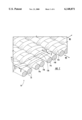
- FIG. 1 is an enlarged perspective view of a portion of a fabric of the present invention.
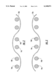
- FIG. 2 is a section view of the fabric of FIG. 1 taken along lines 2--2 of FIG. 1.
- FIG. 3 is a section view of the fabric of FIG. 1 taken along lines 3--3 of FIG. 1.
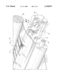
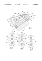
- FIG. 4 is a partial perspective view of an apparatus for slitting thin film into yarns according to the present invention.
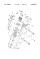
- FIG. 5 is an exploded view of the cutting blade cartridge, mounting block and clamping block of the apparatus of FIG. 4.
- FIG. 6 is an enlarged section view of the assembled blade cartridge, mounting block and clamping block of FIG. 5.
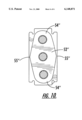
- FIG. 7 is a section view of a blade and spacer of a blade cartridge of FIG. 6.
- FIG. 8 is an alternative embodiment of a blade and spacer arrangement.
- FIG. 9 is a prior art cutting blade and spacer configuration.
- FIG. 10 is another alternative embodiment of a blade and spacer arrangement.
- the fabric 10 includes a plurality of flat film warp yarns 12 extending in a warp direction (designated in FIG. 1 at WA), and further includes a plurality of weft yarns 14 extending in a weft direction (designated in FIG. 1 at WE) that is generally perpendicular to the warp direction. As can be seen in FIG. 1, the weft yarns 14 are interwoven with the flat film warp yarns 12 to form the fabric 10.
- the flat film warp yarns 12 are formed of a flat polymeric thin film.
- the width of each flat film warp yarn 12 is typically between about 0.025 and 0.010 inches, with a width of between about 0.020 and 0.014 inches being preferred.
- the thickness of each flat film warp yarn 12 is between about 20 and 40 ⁇ m, with a thickness of between about 25 and 30 ⁇ m being preferred.
- the flat film warp yarns 12 are formed of a polymeric material.
- Exemplary polymeric materials include polyester, polyethylene, nylon, and blends thereof, with a blend of polyester and polyethylene being preferred. More preferably, the flat film warp yarns 12 are formed of a polyester/polyethylene blend comprising between about 70 to 90 percent polyester and between about 30 to 10 percent polyethylene by weight. These yarns are typically formed of a transparent or translucent polymeric material. Also, the material may include a gloss reducing agent, such as TiO 2 , as well as other fillers.
- the film from which the flat film warp yarns 12 are formed can be made by virtually any method of film forming known to those skilled in this art.
- the film is formed by an extrusion process that causes the polymer chains in the film to be generally aligned in the direction of extrusion. This alignment can add strength to the film in the direction of extrusion, which corresponds to the length dimension of the flat film warp yarns.
- the film may be formed through a blowing process known to those skilled in this art.
- the weft yarns 14 can comprise natural yarns, such as cotton or wool, or synthetic yarns, such as polyester, rayon, nylon, and polypropylene, and blends thereof.
- the weft yarns 14 may be, for example, monofilament or multifilament yarns, and may be spun, cabled, or twisted, or of any other form known to those skilled in this art to be suitable for textile fabrics.
- Such yarns preferably, have a "cotton count" (i.e., the measure of the weight in pounds of 840 yards of the yarn) of 4/1 to 47/1.
- the weft yarns 14 are preferably spun from staple fiber (as opposed to continuous filament yarns.)
- the flat film warp yarns 12 and weft yarns 14 are preferably interwoven in a "double pick" weave, in which each flat film warp yarn 12 passes over a pair of coupled weft yarns 14 (exemplified by weft yarns 14a, 14b), then passes under the next adjacent pair of coupled weft yarns 14 (exemplified by weft yarns 14c, 14d).
- Adjacent flat film warp yarns 12 alternatively pass over and under adjacent coupled pairs of weft yarns 14; for example, the flat film weft yarn 12a passes over the weft yarns 14a, 14b and under the weft yarns 14c, 14d, while the adjacent flat film warp yarn 12b passes under the weft yarns 14a, 14b and over the weft yarns 14c, 14d.
- the fabric 10 is interwoven such that between about forty to seventy flat film warp yarns 12 and approximately 50 to 120 weft yarns 14 are present per square inch of fabric. More preferably, between about fifty and sixty flat film warp yarns 12 and sixty to eighty weft yarns 14 are present per square inch of fabric.
- double picked weave pattern is preferred for some embodiments, single picked weave patterns may also be used.
- double picked yarns are illustrated herein as a plain weave, other weave patterns, such as twills, satins and sateens, may be employed with the present invention.
- the inclusion of the flat film warp yarns 12 can reduce the number of total yarns present per square inch of fabric while maintaining an acceptable texture and fabric appearance.
- a flat film warp yarn 12 formed of 80 percent polyester and 20 percent polyethylene and having a width of 0.020 inches and a thickness of 25 ⁇ m is employed, such a flat film yarn is approximately 3.5 times greater in width than a spun yarn of equal weight.
- fewer warp yarns can be included than for a typical fabric to provide the same "coverage" and barrier (light and batting) properties within the plane of the fabric.
- some additional weft yarns may be desired to increase the weight, (and, in turn, the quality) of the fabric.
- the use of a double-picked weaving pattern provides an unsatisfactory appearance to a fabric, as coupled adjacent weft yarns tend to "pair" with each other; this pairing can create wide spacing between coupled weft yarn pairs and cause a striated appearance.
- the width of the flat film warp yarns 12 tends to match that of the paired weft yearns 14 and thus lends a more balanced (i.e., less striated) look to the fabric 10.
- the coverage provided by the flat film warp yarns 12 causes them to reflect more light than conventional yarns, which also tends to mask the pairing of the weft yarns 14.
- the resulting fabric 10 can have an acceptable appearance and feel at a reduced cost. It may be advantageous to subject the fabric 10 to a surface treatment, such as calendering or sanforizing, as doing so may soften rough edges of the flat film warp yarns 12.
- the flat film warp yarns 12 can also impart a "chintzed" look to the fabric (ie., the fabric has the appearance of polished cotton). Because the flat film warp yarns 12 are formed of a polymeric film, the chintzed appearance may be less prone to fading or otherwise subsiding (i.e. may be more "permanent") than that of prior fabrics.
- the flat film warp yarns 12 of the fabric 10 can be formed from a wider sheet of film in a one-step slitting process.
- the slitting process can be carried out with a slitting apparatus such as that designated at 20 in FIG. 4.
- the slitting apparatus 20 comprises a feed roll 22 over which a thin polymeric film 23 is wrapped, a blade cartridge frame 24 that houses a blade cartridge 26, and a loon beam 28.
- the film 23 is unrolled from the feed roll 22 and passes over the blade cartridge 26, which cuts the film 23 into a plurality of flat film warp yarns 12 that are received on the loom beam 28.
- the flat film warp yarns 12 can be fed into a loom for weaving with weft yarns 14.
- FIG. 5 illustrates the interrelationship of the components of the slitting apparatus 20, including a frame block 30, a clamping block 40, and the blade cartridge 26.
- the frame block 30 includes a floor 32 which is covered by a protective elastomeric pad 33, and further includes an upright panel 34 that extends upwardly from the front edge of the floor 32.
- the clamping block 40 is positioned on the opposite side of the frame block 30 from the upright panel 34.
- the upright panel 34 includes a recess 36 that faces the clamping block 40; likewise, the clamping block 40 includes a recess 42 that faces the upright panel 34.
- the upright panel 34 and clamping block 40 include, respectively, apertures 38, 44 that receive bolts 45 for tightening the clamping block 40 into place.
- apertures 38, 44 that receive bolts 45 for tightening the clamping block 40 into place.
- the blade cartridge 26 includes a plurality of blades 46, each of which is held in spaced apart relation from adjacent blades 46 with spacers 52.
- Each blade 46 (typically about 0.004 inches in thickness) has a pair of cutting edges 48a, 48b along its longer sides and end projections 47a, 47b extending away from either end, such that two planes of symmetry are present: one bisecting the cutting blade 46 lengthwise; and the other bisecting the cutting blade 46 widthwise.
- Each blade 46 also includes an internal cutout area 50.
- Each spacer 52 is somewhat oblong, with parallel opposed edges 53 and rounded ends 54, and includes three interior apertures 56. Like the cutting blades 46, each spacer 52 has two planes of symmetry bisecting the spacer 52 lengthwise and widthwise perpendicular to the plane of the spacer 52. Illustratively and preferably, the spacers 52 are between about 0.010 and 0.040 inches in thickness such that the cutting edges 48a, 48b of the blades 46 are spaced about 0.020 to 0.050 inches apart. Together, the spacers 52 and blades 46 can be sufficiently numerous that, when assembled, the cartridge 26 can be of virtually any length, including up to and beyond 120 inches as needed.
- the blades 46 and spacers 52 are mounted on mounting rods 58a, 58b, 58c, each of which extends through the apertures 56 of the spacers 52 and the cutout portions 50 of the blades 46.
- the cutting blades 46 are in substantially parallel, substantially aligned, spaced apart relationship.
- substantially aligned means that the perimeter of each blade 46 is substantially aligned with the perimeters of adjacent blades in the direction normal to the plane of the blade 46.
- the mounting rods 58a, 58b, 58c are held in place with nuts 60 attached at each end thereof.
- other mounting structures for the cutting blades such as a mounting block with slots to receive the blades, may also be used with the present invention.
- the blade cartridge 26 is secured in place in the blade cartridge frame 24. This is completed by positioning the blade cartridge 26 therein such that end projections 47a of the blades 46 extend within the recess 36 of the upright panel 34, and the end projections 47b of the blades 46 extend within the recess 42 of the clamping block 40. The cutting edges 48b of the blades 46 rest upon the pad 33. The clamping block 40 is then secured to the frame block 30 through tightening of the bolts 45.
- the cutting edges 48a are exposed and therefore able to cut film 23 into flat film warp yarns 12 as it passes over the blades 46 (see FIG. 6) in a general downstream direction D; the width of the flat film yarns 12 is dependent on the distance between cutting edges 48a of adjacent blades 46.
- each spacer 52 is configured such that its edges 53 and ends 54 are recessed from the cutting edges 48a, 48b and end projections 47a, 47b such that either cutting edge 48a, 48b of each blade 46 can be completely exposed when the blade cartridge 26 is mounted in the blade cartridge compartment 43.
- the film 23 can be cut without interference from the spacers 52 irrespective of the orientation of the blade 46 within the blade cartridge 26.
- the rounded ends 54 provide a smooth, nondamaging surface for the film to slide upon after slitting. Therefore, either cutting edge 48a, 48b can be used to cut the film 23, and can be used irrespective of which blade end 47a, 47b is positioned within the recess 36. Consequently, the blades 46 can be used twice as long as a prior art spacer illustrated in FIG. 9, in which the portions of the cutting edges 48a', 48b' near the end 47a' cannot be used.
- the spacers 52 are of sufficient size to support the cutting edges 48a, 48b without undue deflection during slitting.
- the spacer, designated at 52' is a truncated diamond shape, with the wedge-shaped end 54' being recessed such that the spacer 52' fails to interfere with the film 23 as it is cut, but being configured to support the cutting edges of the attached blade.
- the comers 57 of the spacer 52' are preferably rounded somewhat to provide a proper sliding surface for the film after slitting.
- the spacer 52" is a diamond shape with rounded ends 54" and comers 55".
- the slitting apparatus 20 of the present invention can be modified such that it is connected with and provides flat film warp yarns directly to the weaving process.
- the blade cartridge 26 would be mounted onto one end of a loom, and the flat film warp yarns 12, after being slit by the blades 46, would be fed directly into a fabric during weaving.
- the slitting apparatus 20 can be used to produce flat film weft yarns 12 for the fabric 10 in a simple, inexpensive operation.
- flat film warp yarns 12 can be produced at a far lower cost than spun yarns of corresponding size and weight.
- the fabric 10 can be produced considerably less expensively than a corresponding fabric employing spun yarns in place of the flat film warp yarns 12.
- a textile fabric was constructed from slit film warp yarns interwoven with spun weft yarns.
- the warp yarns were cut from a polymer film 25 ⁇ m thick formed of a blend of 80% polyester/20% polyethylene. Slitting was performed at a feed rate of 35 yards/minute on a slitting apparatus such as that illustrated in FIGS. 4 through 7, with the cutting blades mounted 0.020 inches apart.
- the warp yarns were then interwoven in a "double pick" weave pattern with weft yarns formed of 37/1 spun blend of 50% polyester and 50% cotton. After weaving, the fabric was calendered at a speed of 30 yards/minute at room temperature. The finished fabric was observed to have an acceptable appearance and feel.
Abstract
Description
Claims (21)
Priority Applications (8)
| Application Number | Priority Date | Filing Date | Title |
|---|---|---|---|
| US09/184,487 US6148871A (en) | 1998-11-02 | 1998-11-02 | Woven fabric with flat film warp yarns |
| PCT/US1999/022846 WO2000026453A2 (en) | 1998-11-02 | 1999-10-04 | Woven fabric with flat film warp yarns and apparatus for forming same |
| AU65050/99A AU751535B2 (en) | 1998-11-02 | 1999-10-04 | Woven fabric with flat film warp yarns and apparatus for forming same |
| CA002346947A CA2346947A1 (en) | 1998-11-02 | 1999-10-04 | Woven fabric with flat film warp yarns and apparatus for forming same |
| AT99953012T ATE256210T1 (en) | 1998-11-02 | 1999-10-04 | FABRIC WITH WEFT THREAD MADE OF FOIL TAPE AND DEVICE FOR SHAPING THE SAME |
| DE69913561T DE69913561D1 (en) | 1998-11-02 | 1999-10-04 | FABRIC WITH FILM STRAPS AND DEVICE FOR SHAPING THE SAME |
| EP99953012A EP1127180B1 (en) | 1998-11-02 | 1999-10-04 | Woven fabric with flat film warp yarns and apparatus for forming same |
| JP2000579820A JP2002529606A (en) | 1998-11-02 | 1999-10-04 | Woven fabric made of flat film warp and apparatus for forming flat film warp |
Applications Claiming Priority (1)
| Application Number | Priority Date | Filing Date | Title |
|---|---|---|---|
| US09/184,487 US6148871A (en) | 1998-11-02 | 1998-11-02 | Woven fabric with flat film warp yarns |
Publications (1)
| Publication Number | Publication Date |
|---|---|
| US6148871A true US6148871A (en) | 2000-11-21 |
Family
ID=22677084
Family Applications (1)
| Application Number | Title | Priority Date | Filing Date |
|---|---|---|---|
| US09/184,487 Expired - Fee Related US6148871A (en) | 1998-11-02 | 1998-11-02 | Woven fabric with flat film warp yarns |
Country Status (8)
| Country | Link |
|---|---|
| US (1) | US6148871A (en) |
| EP (1) | EP1127180B1 (en) |
| JP (1) | JP2002529606A (en) |
| AT (1) | ATE256210T1 (en) |
| AU (1) | AU751535B2 (en) |
| CA (1) | CA2346947A1 (en) |
| DE (1) | DE69913561D1 (en) |
| WO (1) | WO2000026453A2 (en) |
Cited By (22)
| Publication number | Priority date | Publication date | Assignee | Title |
|---|---|---|---|---|
| US20050191923A1 (en) * | 2003-11-18 | 2005-09-01 | Sun Isle Casual Furniture, Llc | Woven articles from synthetic self twisted yarns |
| US20090260707A1 (en) * | 2008-04-22 | 2009-10-22 | Arun Pal Aneja | Woven Textile Fabric with Cotton/Microdenier Filament Bundle Blend |
| US20120253501A1 (en) * | 2011-03-31 | 2012-10-04 | Springs Creative Products Group, Llc | System and a method for manufacturing substrates for coated fabrics |
| WO2013173035A1 (en) | 2012-05-17 | 2013-11-21 | Honeywell International Inc. | Hybrid fiber unidirectional tape and composite laminates |
| US20140000749A1 (en) * | 2010-10-19 | 2014-01-02 | Tape Weaving Sweden Ab | Method and means for measured control of tape-like warps for shedding and taking-up operations |
| WO2014197050A2 (en) | 2013-03-15 | 2014-12-11 | Honeywell International Inc. | Stab and ballistic resistant articles and the process of making |
| US9131790B2 (en) | 2013-08-15 | 2015-09-15 | Aavn, Inc. | Proliferated thread count of a woven textile by simultaneous insertion within a single pick insertion event of a loom apparatus multiple adjacent parallel yarns drawn from a multi-pick yarn package |
| US9394634B2 (en) | 2014-03-20 | 2016-07-19 | Arun Agarwal | Woven shielding textile impervious to visible and ultraviolet electromagnetic radiation |
| US9474395B2 (en) * | 2015-03-25 | 2016-10-25 | Skr Home Fashion, Inc. | Percale bedding system |
| US9493892B1 (en) | 2012-08-15 | 2016-11-15 | Arun Agarwal | Proliferated thread count of a woven textile by simultaneous insertion within a single pick insertion event of a loom apparatus multiple adjacent parallel yarns drawn from a multi-pick yarn package |
| WO2017048790A1 (en) | 2015-09-17 | 2017-03-23 | Honeywell International Inc. | Low porosity high strength uhmwpe fabrics |
| US9708736B2 (en) | 2014-05-29 | 2017-07-18 | Arun Agarwal | Production of high cotton number or low denier core spun yarn for weaving of reactive fabric and enhanced bedding |
| WO2017180387A1 (en) | 2016-04-15 | 2017-10-19 | Honeywell International Inc. | Blister free composite materials molding |
| US20170313035A1 (en) * | 2016-04-27 | 2017-11-02 | Toyo Tire & Rubber Co., Ltd. | Method of forming topping sheet and apparatus thereof |
| US10443159B2 (en) | 2013-08-15 | 2019-10-15 | Arun Agarwal | Proliferated thread count of a woven textile by simultaneous insertion within a single pick insertion event of a loom apparatus multiple adjacent parallel yarns drawn from a multi-pick yarn package |
| US10443161B1 (en) * | 2018-04-14 | 2019-10-15 | Ronak Rajendra Gupta | High thread/ yarn count woven textile fabric and process of preparation thereof |
| US10456950B2 (en) | 2016-04-27 | 2019-10-29 | Toyo Tire Corporation | Method of forming topping sheet and apparatus thereof |
| US10808337B2 (en) | 2013-08-15 | 2020-10-20 | Arun Agarwal | Proliferated thread count of a woven textile by simultaneous insertion within a single pick insertion event of a loom apparatus multiple adjacent parallel yarns drawn from a multi-pick yarn package |
| US11168414B2 (en) | 2013-08-15 | 2021-11-09 | Arun Agarwal | Selective abrading of a surface of a woven textile fabric with proliferated thread count based on simultaneous insertion within a single pick insertion event of a loom apparatus multiple adjacent parallel yarns drawn from a multi-pick yarn package |
| US11225733B2 (en) | 2018-08-31 | 2022-01-18 | Arun Agarwal | Proliferated thread count of a woven textile by simultaneous insertion within a single pick insertion event of a loom apparatus multiple adjacent parallel yarns drawn from a multi-pick yarn package |
| US11359311B2 (en) | 2013-08-15 | 2022-06-14 | Arun Agarwal | Proliferated thread count of a woven textile by simultaneous insertion within a single pick insertion event of a loom apparatus multiple adjacent parallel yarns drawn from a multi-pick yarn package |
| WO2022212686A1 (en) * | 2021-03-31 | 2022-10-06 | Cooley Group Holdings, Inc. | Composite structures and methods of preparation |
Citations (38)
| Publication number | Priority date | Publication date | Assignee | Title |
|---|---|---|---|---|
| US2533996A (en) * | 1947-11-07 | 1950-12-12 | Us Rubber Co | Fabric slitting machine |
| US2740443A (en) * | 1950-12-23 | 1956-04-03 | William R Brown | Cigarette making and cutting machine |
| US3110905A (en) * | 1961-09-26 | 1963-11-19 | Lees & Sons Co James | Tufted pile fabric comprising a flat woven synthetic plastic backing |
| US3283788A (en) * | 1964-04-07 | 1966-11-08 | Phillips Petroleum Co | Production of woven thermoplastic fabrics |
| US3317366A (en) * | 1962-05-18 | 1967-05-02 | Beaunit Corp | Woven polyester carpet backing and tufted carpet incorporating the same |
| US3327468A (en) * | 1964-07-27 | 1967-06-27 | Hercules Inc | Decorative textile strand and fabric embodying same |
| US3336645A (en) * | 1964-03-10 | 1967-08-22 | Mirsky Alexander | Method and apparatus for preparing warp by dividing sheet material longitudinally |
| US3398220A (en) * | 1964-06-26 | 1968-08-20 | Parker Pace Corp | Process for converting a web of synthetic material into bulk yarns |
| NL6801496A (en) * | 1967-05-03 | 1968-11-04 | ||
| US3503106A (en) * | 1968-06-27 | 1970-03-31 | Avisun Corp | Continuous techniques for making flat woven synthetic fabrics |
| GB1236011A (en) * | 1967-03-07 | 1971-06-16 | Creators Ltd | Improvements in or relating to weaving |
| US3604474A (en) * | 1969-04-22 | 1971-09-14 | Haruo Kamei | Scrubbing bath towel |
| US3611699A (en) * | 1968-03-08 | 1971-10-12 | Eastman Kodak Co | Fibrous yarn product |
| US3626989A (en) * | 1968-12-04 | 1971-12-14 | Alberton Ltd | Weaving method and apparatus |
| US3712344A (en) * | 1968-07-23 | 1973-01-23 | V Kovacec | Strip cutting unit for looms |
| US3789469A (en) * | 1972-02-15 | 1974-02-05 | Fuji Spinning Co Ltd | Yarn treating method |
| FR2259926A1 (en) * | 1974-01-31 | 1975-08-29 | Standard Oil Co | |
| US3918135A (en) * | 1973-09-17 | 1975-11-11 | Hercules Inc | Methods of making fabrics from synthetic tapes |
| US3971279A (en) * | 1975-09-22 | 1976-07-27 | Wright William T | Copy trimmer machine |
| DE2657506A1 (en) * | 1976-12-18 | 1978-06-22 | Messerschmitt Boelkow Blohm | Web cutting bar for dividing material into strips - has row of slits in transverse bar to hold blades parallel to passing web |
| US4107371A (en) * | 1977-10-25 | 1978-08-15 | Johnson & Johnson | Woven fabric that is relatively stiff in one direction and relatively flexible in the other |
| US4107827A (en) * | 1975-01-03 | 1978-08-22 | Chemiefaser Lenzing Aktiengesellschaft | Apparatus for producing synthetic fibers |
| US4118842A (en) * | 1977-07-08 | 1978-10-10 | Champion International Corporation | Weave-de-weave process |
| US4120223A (en) * | 1976-11-15 | 1978-10-17 | Windmoller & Holscher | Apparatus for making tapes |
| US4137614A (en) * | 1976-03-11 | 1979-02-06 | Du Pont Of Canada Limited | Preparation of a warp beam wound with flexible tapes |
| DE3137825A1 (en) * | 1980-09-27 | 1982-05-19 | Barmag Barmer Maschinenfabrik Ag, 5630 Remscheid | Monoaxially oriented laminated-film ribbons |
| US4384018A (en) * | 1982-01-25 | 1983-05-17 | Wayn-Tex Inc. | Secondary carpet backing fabric |
| US4422359A (en) * | 1981-10-07 | 1983-12-27 | The Dow Chemical Company | Adjustable slitter blade holder |
| US4466163A (en) * | 1981-05-11 | 1984-08-21 | Long Barry W | Wide fabric manufacturing method and apparatus |
| US4674380A (en) * | 1986-01-29 | 1987-06-23 | David Hecht | Apparatus for cutting ribbon |
| JPS6392750A (en) * | 1986-10-03 | 1988-04-23 | ダイヤテツクス株式会社 | Carpet base cloth and its production |
| US4819528A (en) * | 1987-12-03 | 1989-04-11 | Essex Manufacturing Company | Ribbon cutting apparatus having multiple, independently driven groups of cutting blades |
| EP0340992A1 (en) * | 1988-05-02 | 1989-11-08 | E.I. Du Pont De Nemours And Company | Woven fabric from splittable ribbons |
| US4947897A (en) * | 1986-04-07 | 1990-08-14 | E. I. Du Pont De Nemours And Company | Method for producing a fabric made from thermoplastic melt impregnated tow |
| US5054524A (en) * | 1988-06-14 | 1991-10-08 | Nippon Seiko K.K. | Solid-color weave pattern belt |
| US5121885A (en) * | 1991-01-02 | 1992-06-16 | Chipman Donald I | Sheet fabric slitter and reroller |
| JP2739302B2 (en) * | 1995-05-23 | 1998-04-15 | 株式会社安岡金銀糸 | Twisted yarn for foil woven and knitted fabric |
| US5902658A (en) * | 1997-08-15 | 1999-05-11 | Wyman; Oliver A. | Dimensionally stable, water impervious rug underlay with double sided pressure sensitive adhesive and protective peelable liners |
Family Cites Families (5)
| Publication number | Priority date | Publication date | Assignee | Title |
|---|---|---|---|---|
| FR892703A (en) * | 1942-09-12 | 1944-05-17 | Goebel Ag | Method and device for making narrow reels of paper |
| DE1927899B2 (en) * | 1969-05-31 | 1972-08-03 | Rheinstahl Ag, 4300 Essen | DEVICE FOR CUTTING TAPES FROM A ROLL OF PLASTIC FILM |
| IE46289B1 (en) * | 1977-01-11 | 1983-04-20 | Newell Co Inc | Synthetic plastics sheets for use in window shades |
| DE9015910U1 (en) * | 1990-11-22 | 1991-02-07 | Maschinenfabrik Goebel Gmbh, 6100 Darmstadt, De | |
| DE19720322C1 (en) * | 1997-05-15 | 1998-05-14 | Saechsisches Textilforsch Inst | Separator parting bands into tapes or fibres which are particularly thin |
-
1998
- 1998-11-02 US US09/184,487 patent/US6148871A/en not_active Expired - Fee Related
-
1999
- 1999-10-04 WO PCT/US1999/022846 patent/WO2000026453A2/en active IP Right Grant
- 1999-10-04 CA CA002346947A patent/CA2346947A1/en not_active Abandoned
- 1999-10-04 DE DE69913561T patent/DE69913561D1/en not_active Expired - Lifetime
- 1999-10-04 EP EP99953012A patent/EP1127180B1/en not_active Expired - Lifetime
- 1999-10-04 AU AU65050/99A patent/AU751535B2/en not_active Ceased
- 1999-10-04 JP JP2000579820A patent/JP2002529606A/en active Pending
- 1999-10-04 AT AT99953012T patent/ATE256210T1/en not_active IP Right Cessation
Patent Citations (38)
| Publication number | Priority date | Publication date | Assignee | Title |
|---|---|---|---|---|
| US2533996A (en) * | 1947-11-07 | 1950-12-12 | Us Rubber Co | Fabric slitting machine |
| US2740443A (en) * | 1950-12-23 | 1956-04-03 | William R Brown | Cigarette making and cutting machine |
| US3110905A (en) * | 1961-09-26 | 1963-11-19 | Lees & Sons Co James | Tufted pile fabric comprising a flat woven synthetic plastic backing |
| US3317366A (en) * | 1962-05-18 | 1967-05-02 | Beaunit Corp | Woven polyester carpet backing and tufted carpet incorporating the same |
| US3336645A (en) * | 1964-03-10 | 1967-08-22 | Mirsky Alexander | Method and apparatus for preparing warp by dividing sheet material longitudinally |
| US3283788A (en) * | 1964-04-07 | 1966-11-08 | Phillips Petroleum Co | Production of woven thermoplastic fabrics |
| US3398220A (en) * | 1964-06-26 | 1968-08-20 | Parker Pace Corp | Process for converting a web of synthetic material into bulk yarns |
| US3327468A (en) * | 1964-07-27 | 1967-06-27 | Hercules Inc | Decorative textile strand and fabric embodying same |
| GB1236011A (en) * | 1967-03-07 | 1971-06-16 | Creators Ltd | Improvements in or relating to weaving |
| NL6801496A (en) * | 1967-05-03 | 1968-11-04 | ||
| US3611699A (en) * | 1968-03-08 | 1971-10-12 | Eastman Kodak Co | Fibrous yarn product |
| US3503106A (en) * | 1968-06-27 | 1970-03-31 | Avisun Corp | Continuous techniques for making flat woven synthetic fabrics |
| US3712344A (en) * | 1968-07-23 | 1973-01-23 | V Kovacec | Strip cutting unit for looms |
| US3626989A (en) * | 1968-12-04 | 1971-12-14 | Alberton Ltd | Weaving method and apparatus |
| US3604474A (en) * | 1969-04-22 | 1971-09-14 | Haruo Kamei | Scrubbing bath towel |
| US3789469A (en) * | 1972-02-15 | 1974-02-05 | Fuji Spinning Co Ltd | Yarn treating method |
| US3918135A (en) * | 1973-09-17 | 1975-11-11 | Hercules Inc | Methods of making fabrics from synthetic tapes |
| FR2259926A1 (en) * | 1974-01-31 | 1975-08-29 | Standard Oil Co | |
| US4107827A (en) * | 1975-01-03 | 1978-08-22 | Chemiefaser Lenzing Aktiengesellschaft | Apparatus for producing synthetic fibers |
| US3971279A (en) * | 1975-09-22 | 1976-07-27 | Wright William T | Copy trimmer machine |
| US4137614A (en) * | 1976-03-11 | 1979-02-06 | Du Pont Of Canada Limited | Preparation of a warp beam wound with flexible tapes |
| US4120223A (en) * | 1976-11-15 | 1978-10-17 | Windmoller & Holscher | Apparatus for making tapes |
| DE2657506A1 (en) * | 1976-12-18 | 1978-06-22 | Messerschmitt Boelkow Blohm | Web cutting bar for dividing material into strips - has row of slits in transverse bar to hold blades parallel to passing web |
| US4118842A (en) * | 1977-07-08 | 1978-10-10 | Champion International Corporation | Weave-de-weave process |
| US4107371A (en) * | 1977-10-25 | 1978-08-15 | Johnson & Johnson | Woven fabric that is relatively stiff in one direction and relatively flexible in the other |
| DE3137825A1 (en) * | 1980-09-27 | 1982-05-19 | Barmag Barmer Maschinenfabrik Ag, 5630 Remscheid | Monoaxially oriented laminated-film ribbons |
| US4466163A (en) * | 1981-05-11 | 1984-08-21 | Long Barry W | Wide fabric manufacturing method and apparatus |
| US4422359A (en) * | 1981-10-07 | 1983-12-27 | The Dow Chemical Company | Adjustable slitter blade holder |
| US4384018A (en) * | 1982-01-25 | 1983-05-17 | Wayn-Tex Inc. | Secondary carpet backing fabric |
| US4674380A (en) * | 1986-01-29 | 1987-06-23 | David Hecht | Apparatus for cutting ribbon |
| US4947897A (en) * | 1986-04-07 | 1990-08-14 | E. I. Du Pont De Nemours And Company | Method for producing a fabric made from thermoplastic melt impregnated tow |
| JPS6392750A (en) * | 1986-10-03 | 1988-04-23 | ダイヤテツクス株式会社 | Carpet base cloth and its production |
| US4819528A (en) * | 1987-12-03 | 1989-04-11 | Essex Manufacturing Company | Ribbon cutting apparatus having multiple, independently driven groups of cutting blades |
| EP0340992A1 (en) * | 1988-05-02 | 1989-11-08 | E.I. Du Pont De Nemours And Company | Woven fabric from splittable ribbons |
| US5054524A (en) * | 1988-06-14 | 1991-10-08 | Nippon Seiko K.K. | Solid-color weave pattern belt |
| US5121885A (en) * | 1991-01-02 | 1992-06-16 | Chipman Donald I | Sheet fabric slitter and reroller |
| JP2739302B2 (en) * | 1995-05-23 | 1998-04-15 | 株式会社安岡金銀糸 | Twisted yarn for foil woven and knitted fabric |
| US5902658A (en) * | 1997-08-15 | 1999-05-11 | Wyman; Oliver A. | Dimensionally stable, water impervious rug underlay with double sided pressure sensitive adhesive and protective peelable liners |
Non-Patent Citations (1)
| Title |
|---|
| Rule 132 Declaration of Stephen Michael Hassell * |
Cited By (32)
| Publication number | Priority date | Publication date | Assignee | Title |
|---|---|---|---|---|
| US7476630B2 (en) * | 2003-11-18 | 2009-01-13 | Casual Living Worldwide, Inc. | Woven articles from synthetic self twisted yarns |
| US7892989B2 (en) | 2003-11-18 | 2011-02-22 | Casual Living Worldwide, Inc. | Woven articles from synthetic self twisted yarns |
| US20050191923A1 (en) * | 2003-11-18 | 2005-09-01 | Sun Isle Casual Furniture, Llc | Woven articles from synthetic self twisted yarns |
| US20090260707A1 (en) * | 2008-04-22 | 2009-10-22 | Arun Pal Aneja | Woven Textile Fabric with Cotton/Microdenier Filament Bundle Blend |
| US20140000749A1 (en) * | 2010-10-19 | 2014-01-02 | Tape Weaving Sweden Ab | Method and means for measured control of tape-like warps for shedding and taking-up operations |
| US9169584B2 (en) * | 2010-10-19 | 2015-10-27 | Tape Weaving Sweden Ab | Method and means for measured control of tape-like warps for shedding and taking-up operations |
| US20120253501A1 (en) * | 2011-03-31 | 2012-10-04 | Springs Creative Products Group, Llc | System and a method for manufacturing substrates for coated fabrics |
| WO2013173035A1 (en) | 2012-05-17 | 2013-11-21 | Honeywell International Inc. | Hybrid fiber unidirectional tape and composite laminates |
| US9493892B1 (en) | 2012-08-15 | 2016-11-15 | Arun Agarwal | Proliferated thread count of a woven textile by simultaneous insertion within a single pick insertion event of a loom apparatus multiple adjacent parallel yarns drawn from a multi-pick yarn package |
| WO2014197050A2 (en) | 2013-03-15 | 2014-12-11 | Honeywell International Inc. | Stab and ballistic resistant articles and the process of making |
| US9708737B2 (en) | 2013-08-15 | 2017-07-18 | Arun Agarwal | Proliferated thread count of a woven textile by simultaneous insertion within a single pick insertion event of a loom apparatus multiple adjacent parallel yarns drawn from a multi-pick yarn package |
| US10443159B2 (en) | 2013-08-15 | 2019-10-15 | Arun Agarwal | Proliferated thread count of a woven textile by simultaneous insertion within a single pick insertion event of a loom apparatus multiple adjacent parallel yarns drawn from a multi-pick yarn package |
| US9481950B2 (en) | 2013-08-15 | 2016-11-01 | Arun Agarwal | Proliferated thread count of a woven textile by simultaneous insertion within a single pick insertion event of a loom apparatus multiple adjacent parallel yarns drawn from a multi-pick yarn package |
| US11359311B2 (en) | 2013-08-15 | 2022-06-14 | Arun Agarwal | Proliferated thread count of a woven textile by simultaneous insertion within a single pick insertion event of a loom apparatus multiple adjacent parallel yarns drawn from a multi-pick yarn package |
| US11168414B2 (en) | 2013-08-15 | 2021-11-09 | Arun Agarwal | Selective abrading of a surface of a woven textile fabric with proliferated thread count based on simultaneous insertion within a single pick insertion event of a loom apparatus multiple adjacent parallel yarns drawn from a multi-pick yarn package |
| US9131790B2 (en) | 2013-08-15 | 2015-09-15 | Aavn, Inc. | Proliferated thread count of a woven textile by simultaneous insertion within a single pick insertion event of a loom apparatus multiple adjacent parallel yarns drawn from a multi-pick yarn package |
| US10808337B2 (en) | 2013-08-15 | 2020-10-20 | Arun Agarwal | Proliferated thread count of a woven textile by simultaneous insertion within a single pick insertion event of a loom apparatus multiple adjacent parallel yarns drawn from a multi-pick yarn package |
| US10472744B2 (en) | 2013-08-15 | 2019-11-12 | Arun Agarwal | Proliferated thread count of a woven textile by simultaneous insertion within a single pick insertion event of a loom apparatus multiple adjacent parallel yarns drawn from a multi-pick yarn package |
| US10066324B2 (en) | 2013-08-15 | 2018-09-04 | Arun Agarwal | Proliferated thread count of a woven textile by simultaneous insertion within a single pick insertion event of a loom apparatus multiple adjacent parallel yarns drawn from a multi-pick yarn package |
| US9394634B2 (en) | 2014-03-20 | 2016-07-19 | Arun Agarwal | Woven shielding textile impervious to visible and ultraviolet electromagnetic radiation |
| US9777411B2 (en) | 2014-03-20 | 2017-10-03 | Arun Agarwal | Woven shielding textile impervious to visible and ultraviolet electromagnetic radiation |
| US10428445B2 (en) | 2014-05-29 | 2019-10-01 | Arun Agarwal | Production of high cotton number or low denier core spun yarn for weaving of reactive fabric and enhanced bedding |
| US9708736B2 (en) | 2014-05-29 | 2017-07-18 | Arun Agarwal | Production of high cotton number or low denier core spun yarn for weaving of reactive fabric and enhanced bedding |
| US9474395B2 (en) * | 2015-03-25 | 2016-10-25 | Skr Home Fashion, Inc. | Percale bedding system |
| WO2017048790A1 (en) | 2015-09-17 | 2017-03-23 | Honeywell International Inc. | Low porosity high strength uhmwpe fabrics |
| WO2017180387A1 (en) | 2016-04-15 | 2017-10-19 | Honeywell International Inc. | Blister free composite materials molding |
| US10456950B2 (en) | 2016-04-27 | 2019-10-29 | Toyo Tire Corporation | Method of forming topping sheet and apparatus thereof |
| US20170313035A1 (en) * | 2016-04-27 | 2017-11-02 | Toyo Tire & Rubber Co., Ltd. | Method of forming topping sheet and apparatus thereof |
| US10538066B2 (en) * | 2016-04-27 | 2020-01-21 | Toyo Tire Corporation | Method of forming topping sheet and apparatus thereof |
| US10443161B1 (en) * | 2018-04-14 | 2019-10-15 | Ronak Rajendra Gupta | High thread/ yarn count woven textile fabric and process of preparation thereof |
| US11225733B2 (en) | 2018-08-31 | 2022-01-18 | Arun Agarwal | Proliferated thread count of a woven textile by simultaneous insertion within a single pick insertion event of a loom apparatus multiple adjacent parallel yarns drawn from a multi-pick yarn package |
| WO2022212686A1 (en) * | 2021-03-31 | 2022-10-06 | Cooley Group Holdings, Inc. | Composite structures and methods of preparation |
Also Published As
| Publication number | Publication date |
|---|---|
| EP1127180B1 (en) | 2003-12-10 |
| AU6505099A (en) | 2000-05-22 |
| WO2000026453A2 (en) | 2000-05-11 |
| ATE256210T1 (en) | 2003-12-15 |
| WO2000026453A3 (en) | 2000-09-28 |
| CA2346947A1 (en) | 2000-05-11 |
| EP1127180A2 (en) | 2001-08-29 |
| JP2002529606A (en) | 2002-09-10 |
| DE69913561D1 (en) | 2004-01-22 |
| AU751535B2 (en) | 2002-08-22 |
Similar Documents
| Publication | Publication Date | Title |
|---|---|---|
| US6148871A (en) | Woven fabric with flat film warp yarns | |
| US5618624A (en) | Formable, heat-stabilizable textile pile material | |
| US5654067A (en) | Formable, heat-stabilizable textile loop pile material | |
| US6537640B1 (en) | Pile fabric | |
| US3889305A (en) | Heat barrier textile material | |
| EP2642003B1 (en) | Fabric and clothing | |
| US20180080151A1 (en) | Performance fabrics and related articles | |
| US10323341B2 (en) | Highly air-permeable woven fabric resistant to washing | |
| US4384018A (en) | Secondary carpet backing fabric | |
| JPH09250050A (en) | Sound absorbing cloth and sound absorbing curtain | |
| US20170051440A1 (en) | Outdoor fabric | |
| US20070281158A1 (en) | UV and flame resistant textile polymer yarn | |
| US20030114063A1 (en) | Polyester hospitality fabrics | |
| US10221505B1 (en) | Textile products incorporating banana or raffia fiber and methods of fabricating the same | |
| US6211099B1 (en) | Substrate fabric | |
| MXPA01004421A (en) | Woven fabric with flat film warp yarns and apparatus for forming same | |
| EP4350060A1 (en) | Double raschel knitted fabric and upholstery material containing same | |
| CN113383120A (en) | Open mesh leno fabric, bag made therefrom and method of making leno fabric | |
| IE42077B1 (en) | Polyolefin ribbon yarn fabrics | |
| JP3072422B2 (en) | Interior fabric | |
| JP2022054364A (en) | Slip-suppressed pile fabric, and production method of the same | |
| CN113737353A (en) | Preparation method of multi-environment application comfortable home textile fabric | |
| JP2005232610A (en) | Composite slub yarn and method for producing the same and woven or knitted fabric | |
| CA1072311A (en) | Method of aftertreating woven textile | |
| JPH0313341B2 (en) |
Legal Events
| Date | Code | Title | Description |
|---|---|---|---|
| AS | Assignment |
Owner name: SPRING INDUSTRIES, INC., SOUTH CAROLINA Free format text: ASSIGNMENT OF ASSIGNORS INTEREST;ASSIGNORS:HASSELL, STEPHEN MICHAEL;WEBER, HAROLD FRANCIS;DUNN, RONALD LEEFATE;AND OTHERS;REEL/FRAME:009674/0622 Effective date: 19981214 |
|
| AS | Assignment |
Owner name: THE CHASE MANHATTAN BANK, AS COLLATERAL AGENT, NEW Free format text: SECURITY INTEREST;ASSIGNOR:SPRINGS INDUSTRIES, INC.;REEL/FRAME:012177/0667 Effective date: 20010905 |
|
| FPAY | Fee payment |
Year of fee payment: 4 |
|
| FEPP | Fee payment procedure |
Free format text: PAYER NUMBER DE-ASSIGNED (ORIGINAL EVENT CODE: RMPN); ENTITY STATUS OF PATENT OWNER: LARGE ENTITY Free format text: PAYOR NUMBER ASSIGNED (ORIGINAL EVENT CODE: ASPN); ENTITY STATUS OF PATENT OWNER: LARGE ENTITY |
|
| FEPP | Fee payment procedure |
Free format text: PAYOR NUMBER ASSIGNED (ORIGINAL EVENT CODE: ASPN); ENTITY STATUS OF PATENT OWNER: LARGE ENTITY |
|
| REMI | Maintenance fee reminder mailed | ||
| LAPS | Lapse for failure to pay maintenance fees | ||
| STCH | Information on status: patent discontinuation |
Free format text: PATENT EXPIRED DUE TO NONPAYMENT OF MAINTENANCE FEES UNDER 37 CFR 1.362 |
|
| FP | Lapsed due to failure to pay maintenance fee |
Effective date: 20081121 |