US6148938A - Wear resistant cutter insert structure and method - Google Patents
Wear resistant cutter insert structure and method Download PDFInfo
- Publication number
- US6148938A US6148938A US09/175,906 US17590698A US6148938A US 6148938 A US6148938 A US 6148938A US 17590698 A US17590698 A US 17590698A US 6148938 A US6148938 A US 6148938A
- Authority
- US
- United States
- Prior art keywords
- face
- primary
- tapered
- tapered ridge
- ridge
- Prior art date
- Legal status (The legal status is an assumption and is not a legal conclusion. Google has not performed a legal analysis and makes no representation as to the accuracy of the status listed.)
- Expired - Fee Related
Links
- 238000000034 method Methods 0.000 title claims abstract description 9
- 239000003082 abrasive agent Substances 0.000 claims abstract description 28
- 229910003460 diamond Inorganic materials 0.000 claims description 11
- 239000010432 diamond Substances 0.000 claims description 11
- 239000011435 rock Substances 0.000 claims description 11
- 238000005520 cutting process Methods 0.000 claims description 4
- 230000007423 decrease Effects 0.000 claims 2
- 239000000463 material Substances 0.000 description 8
- 238000005553 drilling Methods 0.000 description 6
- 230000015572 biosynthetic process Effects 0.000 description 5
- 230000003247 decreasing effect Effects 0.000 description 5
- 238000005755 formation reaction Methods 0.000 description 5
- 229910052582 BN Inorganic materials 0.000 description 4
- PZNSFCLAULLKQX-UHFFFAOYSA-N Boron nitride Chemical compound N#B PZNSFCLAULLKQX-UHFFFAOYSA-N 0.000 description 4
- 230000008859 change Effects 0.000 description 4
- 230000000712 assembly Effects 0.000 description 3
- 238000000429 assembly Methods 0.000 description 3
- 230000009471 action Effects 0.000 description 2
- 230000032798 delamination Effects 0.000 description 2
- 238000005096 rolling process Methods 0.000 description 2
- UONOETXJSWQNOL-UHFFFAOYSA-N tungsten carbide Chemical compound [W+]#[C-] UONOETXJSWQNOL-UHFFFAOYSA-N 0.000 description 2
- 229910052984 zinc sulfide Inorganic materials 0.000 description 2
- 230000004075 alteration Effects 0.000 description 1
- 230000000694 effects Effects 0.000 description 1
- 238000010438 heat treatment Methods 0.000 description 1
- 238000004519 manufacturing process Methods 0.000 description 1
- 230000002093 peripheral effect Effects 0.000 description 1
- 230000002028 premature Effects 0.000 description 1
- 230000009467 reduction Effects 0.000 description 1
- 230000004044 response Effects 0.000 description 1
- 238000006467 substitution reaction Methods 0.000 description 1
- 239000000758 substrate Substances 0.000 description 1
Images
Classifications
-
- E—FIXED CONSTRUCTIONS
- E21—EARTH DRILLING; MINING
- E21B—EARTH DRILLING, e.g. DEEP DRILLING; OBTAINING OIL, GAS, WATER, SOLUBLE OR MELTABLE MATERIALS OR A SLURRY OF MINERALS FROM WELLS
- E21B10/00—Drill bits
- E21B10/46—Drill bits characterised by wear resisting parts, e.g. diamond inserts
- E21B10/56—Button-type inserts
- E21B10/567—Button-type inserts with preformed cutting elements mounted on a distinct support, e.g. polycrystalline inserts
- E21B10/5673—Button-type inserts with preformed cutting elements mounted on a distinct support, e.g. polycrystalline inserts having a non planar or non circular cutting face
-
- E—FIXED CONSTRUCTIONS
- E21—EARTH DRILLING; MINING
- E21B—EARTH DRILLING, e.g. DEEP DRILLING; OBTAINING OIL, GAS, WATER, SOLUBLE OR MELTABLE MATERIALS OR A SLURRY OF MINERALS FROM WELLS
- E21B10/00—Drill bits
- E21B10/46—Drill bits characterised by wear resisting parts, e.g. diamond inserts
- E21B10/56—Button-type inserts
- E21B10/567—Button-type inserts with preformed cutting elements mounted on a distinct support, e.g. polycrystalline inserts
- E21B10/573—Button-type inserts with preformed cutting elements mounted on a distinct support, e.g. polycrystalline inserts characterised by support details, e.g. the substrate construction or the interface between the substrate and the cutting element
- E21B10/5735—Interface between the substrate and the cutting element
Definitions
- This invention relates generally to the art of earth boring and, more particularly, to a wear resistant cutter insert structure and method.
- An example of a drill bit used for drilling earth bore holes for the exploration and production of oil and gas and the like is a roller cone rock bit.
- This type of bit employs a multiplicity of rolling cone cutters, also known as rotary cone cutters, rotatably mounted on bearing pins extending from arms of the bit.
- the cutters are mounted on pins that extend downwardly and inwardly with respect to an axis through the bit axis so that conical sides of the cutters tend to roll on the bottom of a bore hole and contact an earth formation.
- a number of insert bits or compacts are disposed in the rolling cone cutters to drill the formations at the bottom of the bore hole. These insert bits tend to wear in those areas that engage the bottom and peripheral wall of the bore hole during the drilling operation.
- Each insert bit may include a superhard abrasive material bonded to a stud.
- Abrasive materials such as synthetic or natural diamond, cubic boron nitride, and wurtzite boron nitride are bonded to the stud to increase wear resistance of the insert bit.
- the abrasive material is often referred to as polycrystalline diamond, PDC, or sintered diamond.
- the stud may be comprised of a substrate material such as tungsten carbide.
- One of the factors limiting the wear resistance of the insert bit is the strength of the bond between the polycrystalline diamond and the stud. A weak bond results in decreased wear resistance and premature insert bit failure.
- a wear resistant cutter insert structure and method are provided that address disadvantages and problems associated with prior art cutter insert structures and methods.
- a cutter insert for a roller cone rock bit includes a stud having at least one face. The face has a primary tapered ridge and at least one secondary tapered ridge extending from the primary tapered ridge. A layer of abrasive material is disposed over the face and the primary and secondary tapered ridges.
- a method for fabricating a cutter insert for a roller cone rock bit includes providing a stud having at least one face.
- the face has a primary tapered ridge and at least one secondary tapered ridge extending from the primary tapered ridge.
- the method also includes applying a layer of abrasive material over the face and the primary and secondary tapered ridges.
- the invention provides several technical advantages.
- the invention provides a cutter insert for a roller cone rock bit with increased wear resistance.
- the cutter insert reduces the risk of polycrystalline diamond delamination over conventional cutter inserts by decreasing interfacial shear stresses between the polycrystalline diamond and the stud.
- Other technical advantages are readily apparent to one skilled in the art from the following figures, descriptions, and claims.
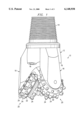
- FIG. 1 is an isometric drawing of a roller cone rock bit
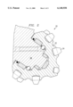
- FIG. 2 is a cross sectional drawing with portions broken away of a support arm of a cutter cone assembly of the roller cone rock bit of FIG. 1;
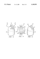
- FIG. 3 is an enlarged drawing of a cutter insert constructed according to the teachings of the present invention.
- FIG. 4 is an enlarged drawing of the cutter insert of FIG. 3 taken along line 4--4 of FIG. 3;
- FIG. 5 is an enlarged drawing of a cutter insert constructed according to the teachings of the present invention after application of polycrystalline diamond.
- FIGS. 1 through 5 of the drawings like numerals being used for like and corresponding parts of the various drawings.
- FIG. 1 illustrates an isometric view of a roller cone rock bit 10.
- Bit 10 includes a bit body 12 adapted to be connected at a pin or threaded connection 14 to a lower end of a rotary drill string (not explicitly shown). Threaded connection 14 and the corresponding threaded connection of the drill string are designed to allow for rotation of bit 10 in response to rotation of the drill string at the well surface (not explicitly shown).
- Bit body 12 includes a passage (not explicitly shown) that provides downward communication for drilling mud or the like passing downwardly through the drill string.
- the drilling mud exits through a number of nozzles 16 and is directed to the bottom of a bore hole and then passes upward in an annulus between a wall of the bore hole and the drill string, carrying cuttings and drilling debris upward and away from the bottom of the bore hole.
- Each support arm 18 rotatably supports a generally conical cutter cone assembly 20.
- Each cutter cone assembly 20 has a defined axis of rotation about which the cutter cone assembly 20 rotates.
- Each cutter cone assembly 20 includes a cutter cone 22.
- Cutter cone 22 includes a number of inserts 24 disposed in a surface of each cutter cone 22.
- Each insert 24 of each cutter cone 22 is generally of the same size; however, different sizes of inserts 24 may be incorporated.
- FIG. 2 illustrates a cross sectional view of the interconnection of one cutter cone assembly 20 and associated support arm 18.
- Each of support arms 18 has a bearing pin or spindle 26 attached to an end of support arm 18 that is opposite bit body 12.
- Cutter cone 22 of each cutter cone assembly 20 is mounted on spindle 26.
- Cutter cone assemblies 20 may sometimes be referred to as “rotary cone cutters” or “roller cone cutters.”
- the cutting action or drilling action of bit 10 occurs as cutter cone assemblies 20 are rolled around the bottom of the bore hole by the rotation of the drill string.
- Inserts 24 contact an earth formation as cutter cone assemblies 20 are rolled around the bottom of the bore hole and operate to scrape and gouge the earth formation.
- FIGS. 3 and 4 illustrate enlarged views of insert 24 constructed according to the teachings of the present invention.
- insert 24 includes a stud 28 including a leading face 30 and a trailing face 32.
- Stud 28 may be constructed from materials such as tungsten carbide.
- Leading face 30 is the surface of insert 24 in the direction of rotation of cutter cone assembly 20.
- Stud 28 also includes a crest face 34.
- Crest face 34 may have a rounded shape, as shown in FIG. 3, or may be formed in other shapes including, but not limited to, planar or pointed (not explicitly shown).
- FIG. 5 is an enlarged view of insert 24 constructed according to the teachings of the present invention after application of a wear resistant material to stud 28.
- the wear resistance of insert 24 may be improved by bonding a superhard abrasive material to certain wear areas of stud 28.
- This superhard abrasive material is often referred to as polycrystalline diamond, PDC, or sintered diamond and may include materials such as synthetic or natural diamond, cubic boron nitride, and wurtzite boron nitride.
- a number of primary tapered ridges 36 are integrally formed in leading face 30, trailing face 32, and crest face 34 of stud 28.
- Stud 28 also includes a number of secondary tapered ridges 38 integrally formed in leading face 30, trailing face 32, and crest face 34 extending from primary tapered ridges 36. As shown best in FIG. 5, a layer 40 of abrasive material is applied to leading face 30, trailing face 32, and crest face 34 covering primary tapered ridges 36 and secondary tapered ridges 38.
- the advantages of the present invention include reducing the effect of thermally-induced interfacial shear stresses created by bonding layer 40 of abrasive material to stud 28.
- Superhard abrasive materials may be bonded to stud 28 at high temperatures and high pressures. Due to different coefficients of thermal expansion between the superhard abrasive material and stud 28, thermally-induced shear stresses are created at an interface between the superhard abrasive material and stud 28. Because of the shear stresses between the superhard abrasive material and stud 28, the superhard abrasive material may delaminate upon impact with an earth formation, upon heating, or upon other disturbances to stud 28.
- thermal expansion is a function of length, temperature, and a coefficient of thermal expansion for a given material:
- Primary tapered ridges 36 and secondary tapered ridges 38 operate to reduce a bonding interface length, reflected by L in the above equation, between layer 40 of abrasive material and leading face 30, trailing face 32, and crest face 34 of stud 28.
- the reduction in bonding interface length between layer 40 of abrasive material and leading face 30, trailing face 32, and crest face 34 of stud 28 results in a decreased change in material length, reflected by ⁇ L in the above equation, of layer 40 of abrasive material and stud 28 during the high temperature and high pressure application of layer 40 of abrasive material to stud 28.
- the resulting decreased change in material length of layer 40 of abrasive material and stud 28 reduces the thermally-induced shear stresses that may cause delamination of layer 40 of abrasive material from stud 28. Therefore, the wear resistance of insert 24 is greater than the wear resistance of conventional inserts.
Abstract
A wear resistant cutter insert structure and method include a stud having at least one face. A primary tapered ridge and at least one secondary tapered ridge extending from the primary tapered ridge are formed in the face. A layer of abrasive material is disposed over the face covering the primary and secondary tapered ridges.
Description
This invention relates generally to the art of earth boring and, more particularly, to a wear resistant cutter insert structure and method.
An example of a drill bit used for drilling earth bore holes for the exploration and production of oil and gas and the like is a roller cone rock bit. This type of bit employs a multiplicity of rolling cone cutters, also known as rotary cone cutters, rotatably mounted on bearing pins extending from arms of the bit. The cutters are mounted on pins that extend downwardly and inwardly with respect to an axis through the bit axis so that conical sides of the cutters tend to roll on the bottom of a bore hole and contact an earth formation. A number of insert bits or compacts are disposed in the rolling cone cutters to drill the formations at the bottom of the bore hole. These insert bits tend to wear in those areas that engage the bottom and peripheral wall of the bore hole during the drilling operation.
Each insert bit may include a superhard abrasive material bonded to a stud. Abrasive materials such as synthetic or natural diamond, cubic boron nitride, and wurtzite boron nitride are bonded to the stud to increase wear resistance of the insert bit. The abrasive material is often referred to as polycrystalline diamond, PDC, or sintered diamond. The stud may be comprised of a substrate material such as tungsten carbide. One of the factors limiting the wear resistance of the insert bit is the strength of the bond between the polycrystalline diamond and the stud. A weak bond results in decreased wear resistance and premature insert bit failure.
Accordingly, a need has arisen for an improved wear resistant cutter insert structure and method that provides improved wear resistance.
In accordance with the teachings of the present invention, a wear resistant cutter insert structure and method are provided that address disadvantages and problems associated with prior art cutter insert structures and methods. According to one embodiment of the present invention, a cutter insert for a roller cone rock bit includes a stud having at least one face. The face has a primary tapered ridge and at least one secondary tapered ridge extending from the primary tapered ridge. A layer of abrasive material is disposed over the face and the primary and secondary tapered ridges.
According to another embodiment of the invention, a method for fabricating a cutter insert for a roller cone rock bit includes providing a stud having at least one face. The face has a primary tapered ridge and at least one secondary tapered ridge extending from the primary tapered ridge. The method also includes applying a layer of abrasive material over the face and the primary and secondary tapered ridges.
The invention provides several technical advantages. For example, the invention provides a cutter insert for a roller cone rock bit with increased wear resistance. In one embodiment of the invention, the cutter insert reduces the risk of polycrystalline diamond delamination over conventional cutter inserts by decreasing interfacial shear stresses between the polycrystalline diamond and the stud. Other technical advantages are readily apparent to one skilled in the art from the following figures, descriptions, and claims.
For a more complete understanding of the present invention and the advantages thereof, reference is now made to the following descriptions taken in connection with the accompanying drawings in which:
FIG. 1 is an isometric drawing of a roller cone rock bit;
FIG. 2 is a cross sectional drawing with portions broken away of a support arm of a cutter cone assembly of the roller cone rock bit of FIG. 1;
FIG. 3 is an enlarged drawing of a cutter insert constructed according to the teachings of the present invention;
FIG. 4 is an enlarged drawing of the cutter insert of FIG. 3 taken along line 4--4 of FIG. 3; and
FIG. 5 is an enlarged drawing of a cutter insert constructed according to the teachings of the present invention after application of polycrystalline diamond.
Embodiments of the present invention and its advantages are best understood by referring to FIGS. 1 through 5 of the drawings, like numerals being used for like and corresponding parts of the various drawings.
FIG. 1 illustrates an isometric view of a roller cone rock bit 10. Bit 10 includes a bit body 12 adapted to be connected at a pin or threaded connection 14 to a lower end of a rotary drill string (not explicitly shown). Threaded connection 14 and the corresponding threaded connection of the drill string are designed to allow for rotation of bit 10 in response to rotation of the drill string at the well surface (not explicitly shown). Bit body 12 includes a passage (not explicitly shown) that provides downward communication for drilling mud or the like passing downwardly through the drill string. The drilling mud exits through a number of nozzles 16 and is directed to the bottom of a bore hole and then passes upward in an annulus between a wall of the bore hole and the drill string, carrying cuttings and drilling debris upward and away from the bottom of the bore hole.
Depending downwardly from bit body 12 are three substantially similar support arms 18. Each support arm 18 rotatably supports a generally conical cutter cone assembly 20. Each cutter cone assembly 20 has a defined axis of rotation about which the cutter cone assembly 20 rotates. Each cutter cone assembly 20 includes a cutter cone 22. Cutter cone 22 includes a number of inserts 24 disposed in a surface of each cutter cone 22. Each insert 24 of each cutter cone 22 is generally of the same size; however, different sizes of inserts 24 may be incorporated.
FIG. 2 illustrates a cross sectional view of the interconnection of one cutter cone assembly 20 and associated support arm 18. Each of support arms 18 has a bearing pin or spindle 26 attached to an end of support arm 18 that is opposite bit body 12. Cutter cone 22 of each cutter cone assembly 20 is mounted on spindle 26. Cutter cone assemblies 20 may sometimes be referred to as "rotary cone cutters" or "roller cone cutters." In operation, the cutting action or drilling action of bit 10 occurs as cutter cone assemblies 20 are rolled around the bottom of the bore hole by the rotation of the drill string. Inserts 24 contact an earth formation as cutter cone assemblies 20 are rolled around the bottom of the bore hole and operate to scrape and gouge the earth formation.
FIGS. 3 and 4 illustrate enlarged views of insert 24 constructed according to the teachings of the present invention. As shown best in FIG. 4, insert 24 includes a stud 28 including a leading face 30 and a trailing face 32. Stud 28 may be constructed from materials such as tungsten carbide. Leading face 30 is the surface of insert 24 in the direction of rotation of cutter cone assembly 20. Stud 28 also includes a crest face 34. Crest face 34 may have a rounded shape, as shown in FIG. 3, or may be formed in other shapes including, but not limited to, planar or pointed (not explicitly shown).
FIG. 5 is an enlarged view of insert 24 constructed according to the teachings of the present invention after application of a wear resistant material to stud 28. The wear resistance of insert 24 may be improved by bonding a superhard abrasive material to certain wear areas of stud 28. This superhard abrasive material is often referred to as polycrystalline diamond, PDC, or sintered diamond and may include materials such as synthetic or natural diamond, cubic boron nitride, and wurtzite boron nitride. In accordance with an embodiment of the present invention, as shown best in FIG. 4, a number of primary tapered ridges 36 are integrally formed in leading face 30, trailing face 32, and crest face 34 of stud 28. Stud 28 also includes a number of secondary tapered ridges 38 integrally formed in leading face 30, trailing face 32, and crest face 34 extending from primary tapered ridges 36. As shown best in FIG. 5, a layer 40 of abrasive material is applied to leading face 30, trailing face 32, and crest face 34 covering primary tapered ridges 36 and secondary tapered ridges 38.
The advantages of the present invention include reducing the effect of thermally-induced interfacial shear stresses created by bonding layer 40 of abrasive material to stud 28. Superhard abrasive materials may be bonded to stud 28 at high temperatures and high pressures. Due to different coefficients of thermal expansion between the superhard abrasive material and stud 28, thermally-induced shear stresses are created at an interface between the superhard abrasive material and stud 28. Because of the shear stresses between the superhard abrasive material and stud 28, the superhard abrasive material may delaminate upon impact with an earth formation, upon heating, or upon other disturbances to stud 28.
In accordance with an embodiment of the present invention, by providing primary tapered ridges 36 and secondary tapered ridges 38 in leading face 30, trailing face 32, and crest face 34 of stud 28, thermally-induced shear stresses between layer 40 of abrasive material and stud 28 are decreased. As shown by the following equation, thermal expansion is a function of length, temperature, and a coefficient of thermal expansion for a given material:
ΔL=αLΔT
where L is length, ΔL is change in length, T is temperature, ΔT is change in temperature, and α is a coefficient of thermal expansion for a given material. Primary tapered ridges 36 and secondary tapered ridges 38 operate to reduce a bonding interface length, reflected by L in the above equation, between layer 40 of abrasive material and leading face 30, trailing face 32, and crest face 34 of stud 28. The reduction in bonding interface length between layer 40 of abrasive material and leading face 30, trailing face 32, and crest face 34 of stud 28 results in a decreased change in material length, reflected by ΔL in the above equation, of layer 40 of abrasive material and stud 28 during the high temperature and high pressure application of layer 40 of abrasive material to stud 28. The resulting decreased change in material length of layer 40 of abrasive material and stud 28 reduces the thermally-induced shear stresses that may cause delamination of layer 40 of abrasive material from stud 28. Therefore, the wear resistance of insert 24 is greater than the wear resistance of conventional inserts.
Although the embodiment of the invention described herein includes a number of primary tapered ridges 36 and secondary tapered ridges 38 in leading face 30, trailing face 32, and crest face 34 of stud 28, the number, location, taper direction, and orientation of primary tapered ridges 36 and secondary tapered ridges 38 in stud 28 may be altered while still providing the advantages described above.
Although the present invention and its advantages have been described in detail, it should be understood that various changes, substitutions, and alterations can be made therein without departing from the spirit and scope of the present invention as defined by the appended claims.
Claims (15)
1. A cutter insert for a roller cone rock bit comprising:
a stud having at least one face, the at least one face having a primary tapered ridge and at least two secondary tapered ridges extending from separate respective points on the primary tapered ridge; and
a layer of abrasive material disposed over the at least one face.
2. The cutter insert of claim 1, wherein the at least one secondary tapered ridge comprises a plurality of secondary tapered ridges extending from the primary tapered ridge.
3. The cutter insert of claim 2, wherein the primary tapered ridge comprises a height, wherein the plurality of secondary tapered ridges comprise a plurality of heights, and wherein the plurality of heights decreases as the height of the primary tapered ridge decreases.
4. The cutter insert of claim 2, wherein the plurality of secondary tapered ridges comprise a plurality of approximately uniformly spaced apart tapered ridges.
5. The cutter insert of claim 1, wherein the at least one face comprises a first face and a second face, the first face having a primary tapered ridge and at least one secondary tapered ridge extending from the primary tapered ridge in the first face, the second face having a primary tapered ridge.
6. The cutter insert of claim 5, wherein the second face comprises a secondary tapered ridge extending from the primary tapered ridge in the second face.
7. The cutter insert of claim 6, wherein the at least one secondary tapered ridge in the second face comprises a plurality of secondary tapered ridges extending from the primary tapered ridge in the second face.
8. The cutter insert of claim 5, wherein the at least one secondary tapered ridge in the first face comprises a plurality of secondary tapered ridges extending from the primary tapered ridge in the first face.
9. The cutter insert of claim 5, wherein an intersection of the first face and the second face forms a crest face, wherein the primary tapered ridge in the first face extends into the crest face.
10. The cutter insert of claim 1, wherein the layer of abrasive material comprises a uniform thickness on the at least one face.
11. The cutter insert of claim 1, wherein the primary tapered ridge comprises a rounded peak.
12. The cutter insert of claim 1, wherein the abrasive material comprises polycrystalline diamond.
13. A roller cone rock bit comprising:
a bit body;
a support arm extending from the bit body; and
a cutter cone coupled to the support arm, the cutter cone having at least one cutting element comprising:
a stud having at least one face, the at least one face having a primary tapered ridge and at least two secondary tapered ridges extending from separate respective points on the primary tapered ridge; and
a layer of abrasive material disposed over the at least one face.
14. A method for fabricating a cutting element for a roller cone rock bit comprising the steps of:
providing a stud having at least one face, the at least one face having a primary tapered ridge and at least two secondary tapered ridges extending from separate respective points on the primary tapered ridge; and
applying a layer of abrasive material over the at least one face.
15. A compact for a roller cone rock bit comprising:
first and second faces which are generally opposite to each other;
a plurality of primary ridges on said first and second faces;
a plurality of secondary ridges, extending from multiple points on the respective crests of said primary ridges; and
a layer of abrasive material disposed over said first and second faces.
Priority Applications (1)
| Application Number | Priority Date | Filing Date | Title |
|---|---|---|---|
| US09/175,906 US6148938A (en) | 1998-10-20 | 1998-10-20 | Wear resistant cutter insert structure and method |
Applications Claiming Priority (1)
| Application Number | Priority Date | Filing Date | Title |
|---|---|---|---|
| US09/175,906 US6148938A (en) | 1998-10-20 | 1998-10-20 | Wear resistant cutter insert structure and method |
Publications (1)
| Publication Number | Publication Date |
|---|---|
| US6148938A true US6148938A (en) | 2000-11-21 |
Family
ID=22642162
Family Applications (1)
| Application Number | Title | Priority Date | Filing Date |
|---|---|---|---|
| US09/175,906 Expired - Fee Related US6148938A (en) | 1998-10-20 | 1998-10-20 | Wear resistant cutter insert structure and method |
Country Status (1)
| Country | Link |
|---|---|
| US (1) | US6148938A (en) |
Cited By (12)
| Publication number | Priority date | Publication date | Assignee | Title |
|---|---|---|---|---|
| US6904984B1 (en) | 2003-06-20 | 2005-06-14 | Rock Bit L.P. | Stepped polycrystalline diamond compact insert |
| US20060249308A1 (en) * | 2003-02-11 | 2006-11-09 | Klaus Tank | Cutting element |
| US20090178856A1 (en) * | 2008-01-16 | 2009-07-16 | Smith International, Inc. | Drill Bit and Cutter Element Having a Fluted Geometry |
| US20100288564A1 (en) * | 2009-05-13 | 2010-11-18 | Baker Hughes Incorporated | Cutting element for use in a drill bit for drilling subterranean formations |
| US8500833B2 (en) | 2009-07-27 | 2013-08-06 | Baker Hughes Incorporated | Abrasive article and method of forming |
| US8757299B2 (en) | 2009-07-08 | 2014-06-24 | Baker Hughes Incorporated | Cutting element and method of forming thereof |
| GB2510341A (en) * | 2013-01-30 | 2014-08-06 | Nov Downhole Eurasia Ltd | A cutting element having a chamfered and grooved cutting edge |
| US8887839B2 (en) | 2009-06-25 | 2014-11-18 | Baker Hughes Incorporated | Drill bit for use in drilling subterranean formations |
| US8978788B2 (en) | 2009-07-08 | 2015-03-17 | Baker Hughes Incorporated | Cutting element for a drill bit used in drilling subterranean formations |
| US9217295B2 (en) * | 2008-04-21 | 2015-12-22 | Baker Hughes Incorporated | Cutting inserts, cones, earth-boring tools having grading features, and related methods |
| WO2017123562A1 (en) * | 2016-01-13 | 2017-07-20 | Schlumberger Technology Corporation | Angled chisel insert |
| US20220290502A1 (en) * | 2019-08-07 | 2022-09-15 | Mmc Ryotec Corporation | Drilling tip and drilling tool |
Citations (33)
| Publication number | Priority date | Publication date | Assignee | Title |
|---|---|---|---|---|
| US2066853A (en) * | 1933-07-18 | 1937-01-05 | Detachable Bit Corp | Heat treatment of cast drill bits |
| US4109737A (en) * | 1976-06-24 | 1978-08-29 | General Electric Company | Rotary drill bit |
| US4629373A (en) * | 1983-06-22 | 1986-12-16 | Megadiamond Industries, Inc. | Polycrystalline diamond body with enhanced surface irregularities |
| US4716975A (en) * | 1987-02-03 | 1988-01-05 | Strata Bit Corporation | Cutting element having a stud and cutting disk bonded thereto |
| US4764434A (en) * | 1987-06-26 | 1988-08-16 | Sandvik Aktiebolag | Diamond tools for rock drilling and machining |
| US4784023A (en) * | 1985-12-05 | 1988-11-15 | Diamant Boart-Stratabit (Usa) Inc. | Cutting element having composite formed of cemented carbide substrate and diamond layer and method of making same |
| US4984642A (en) * | 1989-05-17 | 1991-01-15 | Societe Industrielle De Combustible Nucleaire | Composite tool comprising a polycrystalline diamond active part |
| US5007207A (en) * | 1987-12-22 | 1991-04-16 | Cornelius Phaal | Abrasive product |
| US5037451A (en) * | 1988-08-31 | 1991-08-06 | Burnand Richard P | Manufacture of abrasive products |
| US5120327A (en) * | 1991-03-05 | 1992-06-09 | Diamant-Boart Stratabit (Usa) Inc. | Cutting composite formed of cemented carbide substrate and diamond layer |
| US5161335A (en) * | 1989-08-14 | 1992-11-10 | Debeers Industrial Diamond Division (Proprietary) Limited | Abrasive body |
| US5335738A (en) * | 1990-06-15 | 1994-08-09 | Sandvik Ab | Tools for percussive and rotary crushing rock drilling provided with a diamond layer |
| US5351772A (en) * | 1993-02-10 | 1994-10-04 | Baker Hughes, Incorporated | Polycrystalline diamond cutting element |
| US5355969A (en) * | 1993-03-22 | 1994-10-18 | U.S. Synthetic Corporation | Composite polycrystalline cutting element with improved fracture and delamination resistance |
| US5379854A (en) * | 1993-08-17 | 1995-01-10 | Dennis Tool Company | Cutting element for drill bits |
| US5469927A (en) * | 1992-12-10 | 1995-11-28 | Camco International Inc. | Cutting elements for rotary drill bits |
| US5472376A (en) * | 1992-12-23 | 1995-12-05 | Olmstead; Bruce R. | Tool component |
| US5484330A (en) * | 1993-07-21 | 1996-01-16 | General Electric Company | Abrasive tool insert |
| US5486137A (en) * | 1993-07-21 | 1996-01-23 | General Electric Company | Abrasive tool insert |
| US5494477A (en) * | 1993-08-11 | 1996-02-27 | General Electric Company | Abrasive tool insert |
| US5524719A (en) * | 1995-07-26 | 1996-06-11 | Dennis Tool Company | Internally reinforced polycrystalling abrasive insert |
| US5564511A (en) * | 1995-05-15 | 1996-10-15 | Frushour; Robert H. | Composite polycrystalline compact with improved fracture and delamination resistance |
| US5566779A (en) * | 1995-07-03 | 1996-10-22 | Dennis Tool Company | Insert for a drill bit incorporating a PDC layer having extended side portions |
| US5598750A (en) * | 1993-11-10 | 1997-02-04 | Camco Drilling Group Limited | Elements faced with superhard material |
| US5605198A (en) * | 1993-12-09 | 1997-02-25 | Baker Hughes Incorporated | Stress related placement of engineered superabrasive cutting elements on rotary drag bits |
| US5611649A (en) * | 1994-06-18 | 1997-03-18 | Camco Drilling Group Limited | Elements faced with superhard material |
| US5662720A (en) * | 1996-01-26 | 1997-09-02 | General Electric Company | Composite polycrystalline diamond compact |
| US5669271A (en) * | 1994-12-10 | 1997-09-23 | Camco Drilling Group Limited Of Hycalog | Elements faced with superhard material |
| US5709279A (en) * | 1995-05-18 | 1998-01-20 | Dennis; Mahlon Denton | Drill bit insert with sinusoidal interface |
| US5758733A (en) * | 1996-04-17 | 1998-06-02 | Baker Hughes Incorporated | Earth-boring bit with super-hard cutting elements |
| US5788001A (en) * | 1996-04-18 | 1998-08-04 | Camco Drilling Group Limited Of Hycalog | Elements faced with superhard material |
| US5862873A (en) * | 1995-03-24 | 1999-01-26 | Camco Drilling Group Limited | Elements faced with superhard material |
| US5906246A (en) * | 1996-06-13 | 1999-05-25 | Smith International, Inc. | PDC cutter element having improved substrate configuration |
-
1998
- 1998-10-20 US US09/175,906 patent/US6148938A/en not_active Expired - Fee Related
Patent Citations (37)
| Publication number | Priority date | Publication date | Assignee | Title |
|---|---|---|---|---|
| US2066853A (en) * | 1933-07-18 | 1937-01-05 | Detachable Bit Corp | Heat treatment of cast drill bits |
| US4109737A (en) * | 1976-06-24 | 1978-08-29 | General Electric Company | Rotary drill bit |
| US4629373A (en) * | 1983-06-22 | 1986-12-16 | Megadiamond Industries, Inc. | Polycrystalline diamond body with enhanced surface irregularities |
| US4784023A (en) * | 1985-12-05 | 1988-11-15 | Diamant Boart-Stratabit (Usa) Inc. | Cutting element having composite formed of cemented carbide substrate and diamond layer and method of making same |
| US4716975A (en) * | 1987-02-03 | 1988-01-05 | Strata Bit Corporation | Cutting element having a stud and cutting disk bonded thereto |
| US4764434A (en) * | 1987-06-26 | 1988-08-16 | Sandvik Aktiebolag | Diamond tools for rock drilling and machining |
| US5007207A (en) * | 1987-12-22 | 1991-04-16 | Cornelius Phaal | Abrasive product |
| US5037451A (en) * | 1988-08-31 | 1991-08-06 | Burnand Richard P | Manufacture of abrasive products |
| US4984642A (en) * | 1989-05-17 | 1991-01-15 | Societe Industrielle De Combustible Nucleaire | Composite tool comprising a polycrystalline diamond active part |
| US5161335A (en) * | 1989-08-14 | 1992-11-10 | Debeers Industrial Diamond Division (Proprietary) Limited | Abrasive body |
| US5335738A (en) * | 1990-06-15 | 1994-08-09 | Sandvik Ab | Tools for percussive and rotary crushing rock drilling provided with a diamond layer |
| US5120327A (en) * | 1991-03-05 | 1992-06-09 | Diamant-Boart Stratabit (Usa) Inc. | Cutting composite formed of cemented carbide substrate and diamond layer |
| US5469927A (en) * | 1992-12-10 | 1995-11-28 | Camco International Inc. | Cutting elements for rotary drill bits |
| US5472376A (en) * | 1992-12-23 | 1995-12-05 | Olmstead; Bruce R. | Tool component |
| US5351772A (en) * | 1993-02-10 | 1994-10-04 | Baker Hughes, Incorporated | Polycrystalline diamond cutting element |
| US5355969A (en) * | 1993-03-22 | 1994-10-18 | U.S. Synthetic Corporation | Composite polycrystalline cutting element with improved fracture and delamination resistance |
| US5486137A (en) * | 1993-07-21 | 1996-01-23 | General Electric Company | Abrasive tool insert |
| US5484330A (en) * | 1993-07-21 | 1996-01-16 | General Electric Company | Abrasive tool insert |
| US5494477A (en) * | 1993-08-11 | 1996-02-27 | General Electric Company | Abrasive tool insert |
| US5379854A (en) * | 1993-08-17 | 1995-01-10 | Dennis Tool Company | Cutting element for drill bits |
| US5499688A (en) * | 1993-08-17 | 1996-03-19 | Dennis Tool Company | PDC insert featuring side spiral wear pads |
| US5630479A (en) * | 1993-08-17 | 1997-05-20 | Dennis; Mahlon D. | Cutting element for drill bits |
| US5544713A (en) * | 1993-08-17 | 1996-08-13 | Dennis Tool Company | Cutting element for drill bits |
| US5598750A (en) * | 1993-11-10 | 1997-02-04 | Camco Drilling Group Limited | Elements faced with superhard material |
| US5605198A (en) * | 1993-12-09 | 1997-02-25 | Baker Hughes Incorporated | Stress related placement of engineered superabrasive cutting elements on rotary drag bits |
| US5611649A (en) * | 1994-06-18 | 1997-03-18 | Camco Drilling Group Limited | Elements faced with superhard material |
| US5622233A (en) * | 1994-06-18 | 1997-04-22 | Camco Drilling Group Limited, Of Hycalog | Elements faced with superhard materials |
| US5669271A (en) * | 1994-12-10 | 1997-09-23 | Camco Drilling Group Limited Of Hycalog | Elements faced with superhard material |
| US5862873A (en) * | 1995-03-24 | 1999-01-26 | Camco Drilling Group Limited | Elements faced with superhard material |
| US5564511A (en) * | 1995-05-15 | 1996-10-15 | Frushour; Robert H. | Composite polycrystalline compact with improved fracture and delamination resistance |
| US5709279A (en) * | 1995-05-18 | 1998-01-20 | Dennis; Mahlon Denton | Drill bit insert with sinusoidal interface |
| US5566779A (en) * | 1995-07-03 | 1996-10-22 | Dennis Tool Company | Insert for a drill bit incorporating a PDC layer having extended side portions |
| US5524719A (en) * | 1995-07-26 | 1996-06-11 | Dennis Tool Company | Internally reinforced polycrystalling abrasive insert |
| US5662720A (en) * | 1996-01-26 | 1997-09-02 | General Electric Company | Composite polycrystalline diamond compact |
| US5758733A (en) * | 1996-04-17 | 1998-06-02 | Baker Hughes Incorporated | Earth-boring bit with super-hard cutting elements |
| US5788001A (en) * | 1996-04-18 | 1998-08-04 | Camco Drilling Group Limited Of Hycalog | Elements faced with superhard material |
| US5906246A (en) * | 1996-06-13 | 1999-05-25 | Smith International, Inc. | PDC cutter element having improved substrate configuration |
Cited By (25)
| Publication number | Priority date | Publication date | Assignee | Title |
|---|---|---|---|---|
| US20060249308A1 (en) * | 2003-02-11 | 2006-11-09 | Klaus Tank | Cutting element |
| US8172011B2 (en) | 2003-02-11 | 2012-05-08 | Klaus Tank | Cutting element |
| US20050279534A1 (en) * | 2003-06-20 | 2005-12-22 | Roy Estes | Stepped polycrystalline diamond compact insert |
| US7140448B2 (en) | 2003-06-20 | 2006-11-28 | Ulterra Drilling Technologies, L.P. | Stepped polycrystalline diamond compact insert |
| US6904984B1 (en) | 2003-06-20 | 2005-06-14 | Rock Bit L.P. | Stepped polycrystalline diamond compact insert |
| US20090178856A1 (en) * | 2008-01-16 | 2009-07-16 | Smith International, Inc. | Drill Bit and Cutter Element Having a Fluted Geometry |
| US8028773B2 (en) * | 2008-01-16 | 2011-10-04 | Smith International, Inc. | Drill bit and cutter element having a fluted geometry |
| US9217295B2 (en) * | 2008-04-21 | 2015-12-22 | Baker Hughes Incorporated | Cutting inserts, cones, earth-boring tools having grading features, and related methods |
| US20100288564A1 (en) * | 2009-05-13 | 2010-11-18 | Baker Hughes Incorporated | Cutting element for use in a drill bit for drilling subterranean formations |
| US8887839B2 (en) | 2009-06-25 | 2014-11-18 | Baker Hughes Incorporated | Drill bit for use in drilling subterranean formations |
| US8978788B2 (en) | 2009-07-08 | 2015-03-17 | Baker Hughes Incorporated | Cutting element for a drill bit used in drilling subterranean formations |
| US9816324B2 (en) | 2009-07-08 | 2017-11-14 | Baker Hughes | Cutting element incorporating a cutting body and sleeve and method of forming thereof |
| US8757299B2 (en) | 2009-07-08 | 2014-06-24 | Baker Hughes Incorporated | Cutting element and method of forming thereof |
| US10309157B2 (en) | 2009-07-08 | 2019-06-04 | Baker Hughes Incorporated | Cutting element incorporating a cutting body and sleeve and an earth-boring tool including the cutting element |
| US9957757B2 (en) | 2009-07-08 | 2018-05-01 | Baker Hughes Incorporated | Cutting elements for drill bits for drilling subterranean formations and methods of forming such cutting elements |
| US8500833B2 (en) | 2009-07-27 | 2013-08-06 | Baker Hughes Incorporated | Abrasive article and method of forming |
| US9744646B2 (en) | 2009-07-27 | 2017-08-29 | Baker Hughes Incorporated | Methods of forming abrasive articles |
| US10012030B2 (en) | 2009-07-27 | 2018-07-03 | Baker Hughes, A Ge Company, Llc | Abrasive articles and earth-boring tools |
| US9174325B2 (en) | 2009-07-27 | 2015-11-03 | Baker Hughes Incorporated | Methods of forming abrasive articles |
| GB2510341A (en) * | 2013-01-30 | 2014-08-06 | Nov Downhole Eurasia Ltd | A cutting element having a chamfered and grooved cutting edge |
| US10000975B2 (en) | 2013-01-30 | 2018-06-19 | Nov Downhole Eurasia Limited | Cutting element |
| GB2510341B (en) * | 2013-01-30 | 2019-12-18 | Nov Downhole Eurasia Ltd | Cutting Element |
| WO2017123562A1 (en) * | 2016-01-13 | 2017-07-20 | Schlumberger Technology Corporation | Angled chisel insert |
| US11828108B2 (en) | 2016-01-13 | 2023-11-28 | Schlumberger Technology Corporation | Angled chisel insert |
| US20220290502A1 (en) * | 2019-08-07 | 2022-09-15 | Mmc Ryotec Corporation | Drilling tip and drilling tool |
Similar Documents
| Publication | Publication Date | Title |
|---|---|---|
| US6672406B2 (en) | Multi-aggressiveness cuttting face on PDC cutters and method of drilling subterranean formations | |
| US5469927A (en) | Cutting elements for rotary drill bits | |
| US5279375A (en) | Multidirectional drill bit cutter | |
| US9732562B2 (en) | Earth-boring tools having shaped cutting elements | |
| US9752387B2 (en) | Plow-shaped cutting elements for earth-boring tools, earth-boring tools including such cutting elements, and related methods | |
| US8434573B2 (en) | Degradation assembly | |
| US5890552A (en) | Superabrasive-tipped inserts for earth-boring drill bits | |
| US6123160A (en) | Drill bit with gage definition region | |
| US7000715B2 (en) | Rotary drill bits exhibiting cutting element placement for optimizing bit torque and cutter life | |
| EP0802301B1 (en) | Earth-boring bit with super-hard cutting elements | |
| CA2151899C (en) | Tool component | |
| US6401844B1 (en) | Cutter with complex superabrasive geometry and drill bits so equipped | |
| US6065552A (en) | Cutting elements with binderless carbide layer | |
| US6443249B2 (en) | Rotary drill bits for directional drilling exhibiting variable weight-on-bit dependent cutting characteristics | |
| US6206117B1 (en) | Drilling structure with non-axial gage | |
| US7152701B2 (en) | Cutting element structure for roller cone bit | |
| US6176333B1 (en) | Diamond cap cutting elements with flats | |
| US20080164072A1 (en) | Degradation Assembly | |
| US4607711A (en) | Rotary drill bit with cutting elements having a thin abrasive front layer | |
| US6148938A (en) | Wear resistant cutter insert structure and method | |
| US20060021802A1 (en) | Cutting elements and rotary drill bits including same | |
| US20070125579A1 (en) | Roller Cone Drill Bits With Enhanced Cutting Elements And Cutting Structures | |
| US20240093556A1 (en) | Cutting Elements with Ridged and Inclined Cutting Face | |
| GB2367578A (en) | Rotary drag bit with differing chamfer widths and backrakes | |
| CA2479337A1 (en) | Cutting element structure for roller cone bit |
Legal Events
| Date | Code | Title | Description |
|---|---|---|---|
| AS | Assignment |
Owner name: DRESSER INDUSTRIES, INC., TEXAS Free format text: ASSIGNMENT OF ASSIGNORS INTEREST;ASSIGNOR:BEATON, MICHAEL S.;REEL/FRAME:009543/0486 Effective date: 19980929 |
|
| REMI | Maintenance fee reminder mailed | ||
| LAPS | Lapse for failure to pay maintenance fees | ||
| STCH | Information on status: patent discontinuation |
Free format text: PATENT EXPIRED DUE TO NONPAYMENT OF MAINTENANCE FEES UNDER 37 CFR 1.362 |
|
| FP | Lapsed due to failure to pay maintenance fee |
Effective date: 20041121 |