US6150234A - Trench-diffusion corner rounding in a shallow-trench (STI) process - Google Patents
Trench-diffusion corner rounding in a shallow-trench (STI) process Download PDFInfo
- Publication number
- US6150234A US6150234A US09/465,151 US46515199A US6150234A US 6150234 A US6150234 A US 6150234A US 46515199 A US46515199 A US 46515199A US 6150234 A US6150234 A US 6150234A
- Authority
- US
- United States
- Prior art keywords
- trench
- substep
- hcl
- thermal anneal
- oxidation
- Prior art date
- Legal status (The legal status is an assumption and is not a legal conclusion. Google has not performed a legal analysis and makes no representation as to the accuracy of the status listed.)
- Expired - Lifetime
Links
Images


Classifications
-
- H—ELECTRICITY
- H01—ELECTRIC ELEMENTS
- H01L—SEMICONDUCTOR DEVICES NOT COVERED BY CLASS H10
- H01L21/00—Processes or apparatus adapted for the manufacture or treatment of semiconductor or solid state devices or of parts thereof
- H01L21/70—Manufacture or treatment of devices consisting of a plurality of solid state components formed in or on a common substrate or of parts thereof; Manufacture of integrated circuit devices or of parts thereof
- H01L21/71—Manufacture of specific parts of devices defined in group H01L21/70
- H01L21/76—Making of isolation regions between components
- H01L21/762—Dielectric regions, e.g. EPIC dielectric isolation, LOCOS; Trench refilling techniques, SOI technology, use of channel stoppers
- H01L21/76224—Dielectric regions, e.g. EPIC dielectric isolation, LOCOS; Trench refilling techniques, SOI technology, use of channel stoppers using trench refilling with dielectric materials
- H01L21/76232—Dielectric regions, e.g. EPIC dielectric isolation, LOCOS; Trench refilling techniques, SOI technology, use of channel stoppers using trench refilling with dielectric materials of trenches having a shape other than rectangular or V-shape, e.g. rounded corners, oblique or rounded trench walls
- H01L21/76235—Dielectric regions, e.g. EPIC dielectric isolation, LOCOS; Trench refilling techniques, SOI technology, use of channel stoppers using trench refilling with dielectric materials of trenches having a shape other than rectangular or V-shape, e.g. rounded corners, oblique or rounded trench walls trench shape altered by a local oxidation of silicon process step, e.g. trench corner rounding by LOCOS
Definitions
- the present invention concerns the fabrication of integrated circuits and pertains particularly to trench-diffusion corner rounding in a shallow-trench (STI) process.
- STI shallow-trench
- Shallow trench isolation is gradually replacing conventional local oxidation of silicon (LOCOS) process for the formation of an isolation structure as technology is evolving to submicron geometry.
- STI has various advantages over the conventional LOCOS process. For example, STI allows for the planarization of the isolation structure. This results in better control of critical dimension (CD) when defining a gate stack of a transistor. Better control of CD when defining the gate stack results in better control of CD in further processing steps which occur after the gate stack is defined.
- Shallow Trench Isolation is required because of its planarity, high packing density and low junction edge capacitance.
- a buffer oxide of 10 to 20 nanometers (nm) is thermally grown on wafer substrate.
- a nitride of approximately 200 nm is deposited and then patterned with lithography and etched down to silicon.
- An etch that is selective to silicon (etches mostly silicon) is then used to etch a trench into the silicon.
- a liner oxide is thermally grown to anneal out any damage to the silicon and passivate the silicon.
- an oxide that is considerably thicker than the trench depth is deposited.
- the wafer is then subjected to a chemical-mechanical (CMP) polishing that stops when it reaches the nitride.
- CMP chemical-mechanical
- the top corner of the trench is rounded in order to achieve stable device performance (no kink in the subthreshold slope), reduce inverse narrow width effects and maintain good gate oxide integrity and low junction leakage.
- CMP Chemo-Mechanical Polishing
- the pre-CMP rounding techniques have included Hydrogen annealing (S. Matsuda, et al., Novel Corner Rounding Process for Shallow Trench Isolation utilizing MSTS (Micro-Structure Transformation of Silicon), IEDM Technical Digest, pp. 137-140, 1998) and liner oxidation (see M. Nandakumar, et al., Shallow Trench Isolation for advanced VLSI CMOS Technologies, IEDM Technical Digest, pp. 133-136, 1998) that involves wet or dry oxidation at the proper temperature, time, ambient, and pre-clean.
- Hydrogen annealing S. Matsuda, et al., Novel Corner Rounding Process for Shallow Trench Isolation utilizing MSTS (Micro-Structure Transformation of Silicon), IEDM Technical Digest, pp. 137-140, 1998)
- liner oxidation see M. Nandakumar, et
- the post-CMP rounding techniques have involved high temperature wet oxidation, but if improperly designed can generate stress and lead to dislocation formation in the high stress areas. See F. Nouri, et al., An Optimized Shallow Trench Isolation for sub 0.18 ⁇ m ASIC Technologies, Proc. of Microelectronic Device Technology, SPIE Vol. 3506. pp. 156-166, 1998; and, C. P. Chang, et al., A Highly Manufacturable Corner Rounding Solution for 0.18 ⁇ m Shallow Trench Isolation, IEDM Technical Digest, pp. 661-664, 1997.
- an isolation structure on an integrated circuit is formed using a shallow trench isolation process.
- a trench is formed on a substrate.
- a thermal anneal is performed to oxidize exposed areas of the substrate to provide for round corners at a perimeter of the trench.
- the thermal anneal in performed in an ambient where a chlorine source is added to O 2 in order to minimize facets while creating the round corners. Oxidation time is lengthened by introducing an inert gas during the thermal anneal.
- the thermal anneal is performed at a temperature greater than 1050° C.
- Chlorine is introduced in a furnace oxidation in O 2 plus C 2 H 2 Cl 2 that decomposes to an equivalent 2% HCl.
- the inert gas introduced during oxidation to lengthen oxidation time is, for example, N 2 .
- the rounded corners at the perimeter of the trench increases the threshold voltage of the parasitic transistor at the corners of the trench.
- the rounded corners also allow for oxide at the corners to be thick enough to overcome immediate device failure and reliability issues.
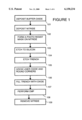
- FIG. 1 is a flowchart for a shallow trench isolation process in accordance with a preferred embodiment of the present invention.
- FIGS. 2, 3, 4, 5, 6, 7, 8 and 9 illustrate the shallow trench isolation process described in FIG. 1 in accordance with a preferred embodiment of the present invention.
- FIG. 1 is a flowchart for a shallow trench isolation process in accordance with a preferred embodiment of the present invention.
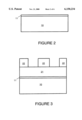
- a layer of buffer (pad) oxide 11 is formed on a substrate 10 of a semiconductor wafer.
- layer of buffer oxide 11 is formed by thermal oxidation of silicon to grow the oxide.
- the layer of buffer oxide is, for example, 10 to 20 nanometers (nm) thick.
- a layer of silicon nitride (Si 3 N 4 ) 21 is formed on top of layer of buffer oxide 11.
- layer of silicon nitride 21 is formed by low pressure chemical vapor deposition (LPCVD, SiH 2 Cl 2 +NH 3 •Dichlorosilane/Ammonia).
- LPCVD low pressure chemical vapor deposition
- SiH 2 Cl 2 +NH 3 •Dichlorosilane/Ammonia The layer of silicon nitride 21 is, for example, approximately 200 nm thick.
- a photoresist pattern 22 is formed on silicon nitride layer 21 using photolithography.
- a dry etch process is used to etch through nitride layer 21 and buffer oxide 11 to substrate 10.
- Etched areas 31 indicate locations in which trenches will be formed.
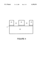
- trenches 51 are formed by, for example, performing a dry etch of the silicon wafer.
- the dry etch can be one or more steps to etch the silicon and smooth out the sidewall profile.
- trenches 51 are 0.25 microns wide and extend 0.3 microns below the surface of substrate 10.
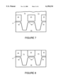
- a layer of liner oxide 61 is thermally grown to anneal out any damage to the sidewalls of trenches 51, to passivate the silicon on the sidewalls, and to provide round corners 42 within the substrate at the edges of the trenches 51.
- the liner oxide is thermally grown in a chlorine oxygen ambient, for example, within a furnace with quartz walls.
- chlorine is introduced in a furnace oxidation at 1075° C. in O 2 plus C 2 H 2 Cl 2 that decomposes to an equivalent 2% HCl.
- O 2 oxygen
- C 2 H 2 Cl 2 C 2 H 2 Cl 2
- improved top corner rounding has been observed.
- the 2% HCl reacts with O 2 to form 1% H 2 O in the furnace and acts to improve the top corner rounding compared to standard dry oxidation at the same temperature.
- Wet oxidation with a conventional pyrogenic torch (at 33% H 2 O) at 1075° C. rounds the corners, but does show more facets than the chlorine process.
- the time should be extended while keeping the oxide thickness the same.
- One way to extend the oxidation time for the same oxide thickness is to lower the temperature. However, when the temperature is lowered, the rounding of the corners suffers.
- Oxidizing for 12 minutes in 2% HCl+O 2 shows good rounding, but intermittent facets on some corners. Just reducing the HCl to 1% for the same conditions and time also shows the same intermittent facets. The more important change is increasing the time by oxidizing for 27 minutes by adding 16 slm of N 2 dilutes the HCl to 0.6%. This dilution slows down the oxidation rate, so that the same oxidation thickness is achieved in the previous cases, but in a longer time. This diluted HCl oxidation process shows less facets and similar rounding.
- the presence of the chlorine during the oxidation retards the (111) plane crystalline growth relative to the (100) plane.
- the advantages of the chlorine oxidation are well rounded corners which minimizes the consumption of the active area and minimize sharp facets.
- the chlorine oxidation process is also very manufacturable running in any state-of-the-art oxidation furnace without any special modification.
- Oxide layer 41 has a thickness of approximately 2 nm to 30 nm. The thickness is chosen for a particular process so that in resulting circuitry, a parasitic transistor at corners 42 has a higher threshold voltage, and gate oxide at corners 42 is thick enough to overcome immediate device failure and reliability issues.
- the degree of rounding for corners 42 can also be varied by changing how much the remaining portions of buffer oxide 11 are recessed under the remaining portions of silicon nitride layer 21, and by varying the amount of undercutting of buffer oxide 11 under silicon nitride layer 21.
- the process creates a very round top comer (radius of curvature of 50 nm).
- the process overcomes poor margin in the rounding process when only O 2 is used in the oxidation process. It is suspected that when a typical (dry) oxidation is performed (without chlorine) changes in the background H 2 O concentration (10-10 3 ppm concentration) change the morphology.
- the dry oxidation at 1150° C. shows facets on the (111) crystalline planes that make the corners less rounded. This occurs because the intrinsic oxidation growth rate on the (111) crystalline planes is faster than (100) crystalline planes for the linear oxidation rate.
- These facets add sharp features to the trench shape that may be detrimental to device performance and die yield, due to stress concentration and high electric fields.
- the key to minimizing facets is to minimize this growth difference and to find the proper ambient and oxidation temperature and time, as described above.
- trenches 51 are filled by high density plasma (HDP) oxide with a fill oxide 71 to a height considerably thicker than the trench depth.
- HDP oxide extends 0.4 micron above the top surface of the remaining portions of silicon nitride layer 21.
- a chemical mechanical polish (CMP) process is performed to polish fill oxide 71 until the height of fill oxide 71 is at the level of the remaining portions of silicon nitride layer 21.
- CMP chemical mechanical polish
- a step 109 illustrated by FIG. 9, the remaining portions of silicon nitride layer 12 and the remaining portions of buffer oxide 11 are stripped away, for example, by a wet etch using a"hot" phosphoric acid solution. This results in shallow trench isolation.
Abstract
Description
Claims (15)
Priority Applications (5)
| Application Number | Priority Date | Filing Date | Title |
|---|---|---|---|
| US09/465,151 US6150234A (en) | 1999-12-16 | 1999-12-16 | Trench-diffusion corner rounding in a shallow-trench (STI) process |
| PCT/US2000/042666 WO2001047010A2 (en) | 1999-12-16 | 2000-12-06 | Trench-diffusion corner rounding in a shallow-trench (sti) process |
| KR1020017010317A KR20010093338A (en) | 1999-12-16 | 2000-12-06 | Trench-diffusion corner rounding in a shallow-trench (sti) process |
| EP00992860A EP1208594A2 (en) | 1999-12-16 | 2000-12-06 | Trench-diffusion corner rounding in a shallow-trench (sti) process |
| JP2001547646A JP2003518741A (en) | 1999-12-16 | 2000-12-06 | Rounding of trench diffusion corners in shallow trench (STI) process |
Applications Claiming Priority (1)
| Application Number | Priority Date | Filing Date | Title |
|---|---|---|---|
| US09/465,151 US6150234A (en) | 1999-12-16 | 1999-12-16 | Trench-diffusion corner rounding in a shallow-trench (STI) process |
Publications (1)
| Publication Number | Publication Date |
|---|---|
| US6150234A true US6150234A (en) | 2000-11-21 |
Family
ID=23846683
Family Applications (1)
| Application Number | Title | Priority Date | Filing Date |
|---|---|---|---|
| US09/465,151 Expired - Lifetime US6150234A (en) | 1999-12-16 | 1999-12-16 | Trench-diffusion corner rounding in a shallow-trench (STI) process |
Country Status (5)
| Country | Link |
|---|---|
| US (1) | US6150234A (en) |
| EP (1) | EP1208594A2 (en) |
| JP (1) | JP2003518741A (en) |
| KR (1) | KR20010093338A (en) |
| WO (1) | WO2001047010A2 (en) |
Cited By (27)
| Publication number | Priority date | Publication date | Assignee | Title |
|---|---|---|---|---|
| US6232181B1 (en) * | 1999-10-21 | 2001-05-15 | United Microelectronics Corp. | Method of forming a flash memory |
| US6326283B1 (en) * | 2000-03-07 | 2001-12-04 | Vlsi Technology, Inc. | Trench-diffusion corner rounding in a shallow-trench (STI) process |
| US6472270B1 (en) * | 2001-03-06 | 2002-10-29 | Advanced Micro Devices, Inc. | Elimination of voids at the oxide/silicon interface in trench-based structures |
| US6486038B1 (en) | 2001-03-12 | 2002-11-26 | Advanced Micro Devices | Method for and device having STI using partial etch trench bottom liner |
| US6514822B2 (en) * | 2001-04-27 | 2003-02-04 | Advanced Micro Devices, Inc. | Method and system for reducing thinning of field isolation structures in a flash memory device |
| US6521510B1 (en) | 2001-03-23 | 2003-02-18 | Advanced Micro Devices, Inc. | Method for shallow trench isolation with removal of strained island edges |
| US6524929B1 (en) | 2001-02-26 | 2003-02-25 | Advanced Micro Devices, Inc. | Method for shallow trench isolation using passivation material for trench bottom liner |
| US6534379B1 (en) | 2001-03-26 | 2003-03-18 | Advanced Micro Devices, Inc. | Linerless shallow trench isolation method |
| US6559031B2 (en) * | 2000-09-25 | 2003-05-06 | Sanyo Electric Co., Ltd. | Method of fabricating semiconductor device having element isolation trench |
| US20040048483A1 (en) * | 2000-06-19 | 2004-03-11 | Heon Lee | Method to etch poly Si gate stacks with raised STI structure |
| WO2004059726A1 (en) | 2002-12-20 | 2004-07-15 | International Business Machines Corporation | Integrated antifuse structure for finfet and cmos devices |
| US6806164B2 (en) * | 2000-05-31 | 2004-10-19 | Oki Electric Industry Co., Ltd. | Semiconductor apparatus and method for fabricating the same |
| US20040214404A1 (en) * | 2003-01-27 | 2004-10-28 | Taishi Kubota | Manufacturing method of semiconductor device and oxidization method of semiconductor substrate |
| US6817903B1 (en) * | 2000-08-09 | 2004-11-16 | Cypress Semiconductor Corporation | Process for reducing leakage in an integrated circuit with shallow trench isolated active areas |
| US20050062127A1 (en) * | 2003-09-19 | 2005-03-24 | Zhihao Chen | Method to form shallow trench isolation with rounded upper corner for advanced semiconductor circuits |
| US6890859B1 (en) | 2001-08-10 | 2005-05-10 | Cypress Semiconductor Corporation | Methods of forming semiconductor structures having reduced defects, and articles and devices formed thereby |
| US20050112841A1 (en) * | 2003-11-24 | 2005-05-26 | Hynix Semiconductor Inc. | Method for isolating semiconductor devices |
| US20050142808A1 (en) * | 2003-12-26 | 2005-06-30 | Nec Electronics Corporation | Method for manufacturing semiconductor device |
| US20060166459A1 (en) * | 2005-01-26 | 2006-07-27 | Elpida Memory, Inc. | Semiconductor apparatus and method of producing the same |
| CN100416833C (en) * | 2005-03-10 | 2008-09-03 | 台湾积体电路制造股份有限公司 | Semiconductor component and its forming method |
| US20080227266A1 (en) * | 2007-03-14 | 2008-09-18 | Texas Instruments Inc. | Method of STI corner rounding using nitridation and high temperature thermal processing |
| CN100433291C (en) * | 2005-06-30 | 2008-11-12 | 茂德科技股份有限公司(新加坡子公司) | Use of chlorine to fabricate trench dielectric in integrated circuits |
| US20080315352A1 (en) * | 2007-06-22 | 2008-12-25 | Lim Hyun-Ju | Method of manufacturing semiconductor device |
| EP1394852A3 (en) * | 2002-08-30 | 2009-03-04 | Fujitsu Microelectronics Limited | Semiconductor device and method of fabricating the same |
| US8551877B2 (en) * | 2012-03-07 | 2013-10-08 | Tokyo Electron Limited | Sidewall and chamfer protection during hard mask removal for interconnect patterning |
| US8703577B1 (en) * | 2012-12-17 | 2014-04-22 | United Microelectronics Corp. | Method for fabrication deep trench isolation structure |
| CN104701155A (en) * | 2013-12-09 | 2015-06-10 | 中芯国际集成电路制造(上海)有限公司 | Gate oxide layer manufacturing method |
Families Citing this family (1)
| Publication number | Priority date | Publication date | Assignee | Title |
|---|---|---|---|---|
| JP2007035823A (en) * | 2005-07-26 | 2007-02-08 | Elpida Memory Inc | Trench forming method, semiconductor device and manufacturing method thereof |
Citations (7)
| Publication number | Priority date | Publication date | Assignee | Title |
|---|---|---|---|---|
| US5719085A (en) * | 1995-09-29 | 1998-02-17 | Intel Corporation | Shallow trench isolation technique |
| US5830797A (en) * | 1996-06-20 | 1998-11-03 | Cypress Semiconductor Corporation | Interconnect methods and apparatus |
| US5854505A (en) * | 1992-12-25 | 1998-12-29 | Sony Corporation | Process for forming silicon oxide film and gate oxide film for MOS transistors |
| US5895254A (en) * | 1997-10-09 | 1999-04-20 | United Microelectronics Corp. | Method of manufacturing shallow trench isolation structure |
| US5920779A (en) * | 1997-05-21 | 1999-07-06 | United Microelectronics Corp. | Differential gate oxide thickness by nitrogen implantation for mixed mode and embedded VLSI circuits |
| US5970363A (en) * | 1997-12-18 | 1999-10-19 | Advanced Micro Devices, Inc. | Shallow trench isolation formation with improved trench edge oxide |
| US6001706A (en) * | 1997-12-08 | 1999-12-14 | Chartered Semiconductor Manufacturing, Ltd. | Method for making improved shallow trench isolation for semiconductor integrated circuits |
Family Cites Families (3)
| Publication number | Priority date | Publication date | Assignee | Title |
|---|---|---|---|---|
| US4735824A (en) * | 1985-05-31 | 1988-04-05 | Kabushiki Kaisha Toshiba | Method of manufacturing an MOS capacitor |
| US5891809A (en) * | 1995-09-29 | 1999-04-06 | Intel Corporation | Manufacturable dielectric formed using multiple oxidation and anneal steps |
| US5863827A (en) * | 1997-06-03 | 1999-01-26 | Texas Instruments Incorporated | Oxide deglaze before sidewall oxidation of mesa or trench |
-
1999
- 1999-12-16 US US09/465,151 patent/US6150234A/en not_active Expired - Lifetime
-
2000
- 2000-12-06 KR KR1020017010317A patent/KR20010093338A/en not_active Application Discontinuation
- 2000-12-06 WO PCT/US2000/042666 patent/WO2001047010A2/en not_active Application Discontinuation
- 2000-12-06 EP EP00992860A patent/EP1208594A2/en not_active Withdrawn
- 2000-12-06 JP JP2001547646A patent/JP2003518741A/en active Pending
Patent Citations (7)
| Publication number | Priority date | Publication date | Assignee | Title |
|---|---|---|---|---|
| US5854505A (en) * | 1992-12-25 | 1998-12-29 | Sony Corporation | Process for forming silicon oxide film and gate oxide film for MOS transistors |
| US5719085A (en) * | 1995-09-29 | 1998-02-17 | Intel Corporation | Shallow trench isolation technique |
| US5830797A (en) * | 1996-06-20 | 1998-11-03 | Cypress Semiconductor Corporation | Interconnect methods and apparatus |
| US5920779A (en) * | 1997-05-21 | 1999-07-06 | United Microelectronics Corp. | Differential gate oxide thickness by nitrogen implantation for mixed mode and embedded VLSI circuits |
| US5895254A (en) * | 1997-10-09 | 1999-04-20 | United Microelectronics Corp. | Method of manufacturing shallow trench isolation structure |
| US6001706A (en) * | 1997-12-08 | 1999-12-14 | Chartered Semiconductor Manufacturing, Ltd. | Method for making improved shallow trench isolation for semiconductor integrated circuits |
| US5970363A (en) * | 1997-12-18 | 1999-10-19 | Advanced Micro Devices, Inc. | Shallow trench isolation formation with improved trench edge oxide |
Non-Patent Citations (14)
| Title |
|---|
| A. Chatterjee, et al. Integration of unit processing in a shalow trench isolation module for a 0.25 m complementary metal oxide semiconductor technology , J. Vac. Technol. B 15(6) Nov./Dec. 1977, pp. 1936 1942. * |
| A. Chatterjee, et al. Integration of unit processing in a shalow trench isolation module for a 0.25 μm complementary metal-oxide semiconductor technology, J. Vac. Technol. B 15(6) Nov./Dec. 1977, pp. 1936-1942. |
| B. E. Deal, et al., Kinetics of the Thermal Oxidation of Silicon in O 2 /H 2 O and O 2 /Cl 2 Mixtures , J. Electrochem. Soc. vol. 125, p. 339 346, 1978. * |
| B. E. Deal, et al., Kinetics of the Thermal Oxidation of Silicon in O2 /H2 O and O2 /Cl2 Mixtures, J. Electrochem. Soc. vol. 125, p. 339-346, 1978. |
| C. P. Chang, et al., A Highly Manufacturable Corner Rounding Solution for 0.18 m Shallow Trench Isolation , IEDM Technical Digest, pp. 661 664, 1997. * |
| C. P. Chang, et al., A Highly Manufacturable Corner Rounding Solution for 0.18 μm Shallow Trench Isolation, IEDM Technical Digest, pp. 661-664, 1997. |
| Dah Bin Kao, Two Dimensional Oxidation Effects in Silicon Experiments and Theory , Ph.D. Thesis, Stanford, Jun. 1986. * |
| Dah-Bin Kao, Two Dimensional Oxidation Effects in Silicon Experiments and Theory, Ph.D. Thesis, Stanford, Jun. 1986. |
| K. Ishimaru, et al. Trench Isolation Technology with 1 m Depth n and p wells for A Full CMOS SRAM Cell with j.4 m n /p Spacing , 1994 Symposium on VLSI Technology Digest of Technical Papers. * |
| K. Ishimaru, et al. Trench Isolation Technology with 1μm Depth n- and p-wells for A Full-CMOS SRAM Cell with j.4 μm n+/p+ Spacing, 1994 Symposium on VLSI Technology Digest of Technical Papers. |
| P. Pan et al., Trench Corner Rounding by Using Rapid Thermal Oxidation in NF 3 /O 2 / Ar ambient ECA Fall Meeting 1994, Extending Abstract, p. 748 749. * |
| P. Pan et al., Trench Corner Rounding by Using Rapid Thermal Oxidation in NF3 /O2 /Ar ambientECA Fall Meeting 1994, Extending Abstract, p. 748-749. |
| S. Matsuda, et al., Novel Corner Rounding Process for Shallow Trench Isolation utilizing MSTS ( Micro Structure Transformation of Silicon ),IEDM Technical Digest, pp. 137 140, 1988. * |
| S. Matsuda, et al., Novel Corner Rounding Process for Shallow Trench Isolation utilizing MSTS (Micro-Structure Transformation of Silicon),IEDM Technical Digest, pp. 137-140, 1988. |
Cited By (37)
| Publication number | Priority date | Publication date | Assignee | Title |
|---|---|---|---|---|
| US6232181B1 (en) * | 1999-10-21 | 2001-05-15 | United Microelectronics Corp. | Method of forming a flash memory |
| US6326283B1 (en) * | 2000-03-07 | 2001-12-04 | Vlsi Technology, Inc. | Trench-diffusion corner rounding in a shallow-trench (STI) process |
| US6806164B2 (en) * | 2000-05-31 | 2004-10-19 | Oki Electric Industry Co., Ltd. | Semiconductor apparatus and method for fabricating the same |
| US20040048483A1 (en) * | 2000-06-19 | 2004-03-11 | Heon Lee | Method to etch poly Si gate stacks with raised STI structure |
| US7153781B2 (en) | 2000-06-19 | 2006-12-26 | Infineon Technologies Ag | Method to etch poly Si gate stacks with raised STI structure |
| US6817903B1 (en) * | 2000-08-09 | 2004-11-16 | Cypress Semiconductor Corporation | Process for reducing leakage in an integrated circuit with shallow trench isolated active areas |
| US6559031B2 (en) * | 2000-09-25 | 2003-05-06 | Sanyo Electric Co., Ltd. | Method of fabricating semiconductor device having element isolation trench |
| US6524929B1 (en) | 2001-02-26 | 2003-02-25 | Advanced Micro Devices, Inc. | Method for shallow trench isolation using passivation material for trench bottom liner |
| US6747333B1 (en) | 2001-02-26 | 2004-06-08 | Advanced Micro Devices, Inc. | Method and apparatus for STI using passivation material for trench bottom liner |
| US6472270B1 (en) * | 2001-03-06 | 2002-10-29 | Advanced Micro Devices, Inc. | Elimination of voids at the oxide/silicon interface in trench-based structures |
| US6486038B1 (en) | 2001-03-12 | 2002-11-26 | Advanced Micro Devices | Method for and device having STI using partial etch trench bottom liner |
| US6521510B1 (en) | 2001-03-23 | 2003-02-18 | Advanced Micro Devices, Inc. | Method for shallow trench isolation with removal of strained island edges |
| US6534379B1 (en) | 2001-03-26 | 2003-03-18 | Advanced Micro Devices, Inc. | Linerless shallow trench isolation method |
| US6514822B2 (en) * | 2001-04-27 | 2003-02-04 | Advanced Micro Devices, Inc. | Method and system for reducing thinning of field isolation structures in a flash memory device |
| US6890859B1 (en) | 2001-08-10 | 2005-05-10 | Cypress Semiconductor Corporation | Methods of forming semiconductor structures having reduced defects, and articles and devices formed thereby |
| EP1394852A3 (en) * | 2002-08-30 | 2009-03-04 | Fujitsu Microelectronics Limited | Semiconductor device and method of fabricating the same |
| WO2004059726A1 (en) | 2002-12-20 | 2004-07-15 | International Business Machines Corporation | Integrated antifuse structure for finfet and cmos devices |
| CN100401498C (en) * | 2003-01-27 | 2008-07-09 | 尔必达存储器株式会社 | Manufacturing method of semiconductor device and oxidization method of semiconductor substrate |
| US7163871B2 (en) * | 2003-01-27 | 2007-01-16 | Elpida Memory, Inc. | Manufacturing method of semiconductor device and oxidization method of semiconductor substrate |
| US20040214404A1 (en) * | 2003-01-27 | 2004-10-28 | Taishi Kubota | Manufacturing method of semiconductor device and oxidization method of semiconductor substrate |
| US20050062127A1 (en) * | 2003-09-19 | 2005-03-24 | Zhihao Chen | Method to form shallow trench isolation with rounded upper corner for advanced semiconductor circuits |
| US6917093B2 (en) * | 2003-09-19 | 2005-07-12 | Texas Instruments Incorporated | Method to form shallow trench isolation with rounded upper corner for advanced semiconductor circuits |
| US20050208732A1 (en) * | 2003-09-19 | 2005-09-22 | Zhihao Chen | Method to form shallow trench isolation with rounded upper corner for advanced semiconductor circuits |
| US7504339B2 (en) * | 2003-09-19 | 2009-03-17 | Texas Instruments Incorporated | Method to form shallow trench isolation with rounded upper corner for advanced semiconductor circuits |
| US20050112841A1 (en) * | 2003-11-24 | 2005-05-26 | Hynix Semiconductor Inc. | Method for isolating semiconductor devices |
| US20050142808A1 (en) * | 2003-12-26 | 2005-06-30 | Nec Electronics Corporation | Method for manufacturing semiconductor device |
| US7279376B2 (en) * | 2003-12-26 | 2007-10-09 | Nec Electronics Corporation | Method for manufacturing semiconductor device |
| US20060166459A1 (en) * | 2005-01-26 | 2006-07-27 | Elpida Memory, Inc. | Semiconductor apparatus and method of producing the same |
| CN100416833C (en) * | 2005-03-10 | 2008-09-03 | 台湾积体电路制造股份有限公司 | Semiconductor component and its forming method |
| CN100433291C (en) * | 2005-06-30 | 2008-11-12 | 茂德科技股份有限公司(新加坡子公司) | Use of chlorine to fabricate trench dielectric in integrated circuits |
| US20080227266A1 (en) * | 2007-03-14 | 2008-09-18 | Texas Instruments Inc. | Method of STI corner rounding using nitridation and high temperature thermal processing |
| WO2008112859A1 (en) * | 2007-03-14 | 2008-09-18 | Texas Instruments Incorporated | Method of sti corner rounding using nitridation and high temperature thermal processing |
| US20080315352A1 (en) * | 2007-06-22 | 2008-12-25 | Lim Hyun-Ju | Method of manufacturing semiconductor device |
| US7745304B2 (en) * | 2007-06-22 | 2010-06-29 | Dongbu Hitek Co., Ltd. | Method of manufacturing semiconductor device |
| US8551877B2 (en) * | 2012-03-07 | 2013-10-08 | Tokyo Electron Limited | Sidewall and chamfer protection during hard mask removal for interconnect patterning |
| US8703577B1 (en) * | 2012-12-17 | 2014-04-22 | United Microelectronics Corp. | Method for fabrication deep trench isolation structure |
| CN104701155A (en) * | 2013-12-09 | 2015-06-10 | 中芯国际集成电路制造(上海)有限公司 | Gate oxide layer manufacturing method |
Also Published As
| Publication number | Publication date |
|---|---|
| KR20010093338A (en) | 2001-10-27 |
| JP2003518741A (en) | 2003-06-10 |
| EP1208594A2 (en) | 2002-05-29 |
| WO2001047010A3 (en) | 2002-03-21 |
| WO2001047010A2 (en) | 2001-06-28 |
Similar Documents
| Publication | Publication Date | Title |
|---|---|---|
| US6150234A (en) | Trench-diffusion corner rounding in a shallow-trench (STI) process | |
| US6326283B1 (en) | Trench-diffusion corner rounding in a shallow-trench (STI) process | |
| US7407868B2 (en) | Chemical thinning of silicon body of an SOI substrate | |
| KR960016502B1 (en) | Integrated circuit isolation method | |
| US6001706A (en) | Method for making improved shallow trench isolation for semiconductor integrated circuits | |
| US5747377A (en) | Process for forming shallow trench isolation | |
| US8541270B2 (en) | Finlike structures and methods of making same | |
| US7482210B2 (en) | Method of fabricating semiconductor device having junction isolation insulating layer | |
| US9111884B2 (en) | Finlike structures and methods of making same | |
| US20030049893A1 (en) | Method for isolating semiconductor devices | |
| KR100381399B1 (en) | Manufacture of semiconductor device | |
| US6033991A (en) | Isolation scheme based on recessed locos using a sloped Si etch and dry field oxidation | |
| US6355539B1 (en) | Method for forming shallow trench isolation | |
| US6054368A (en) | Method of making an improved field oxide isolation structure for semiconductor integrated circuits having higher field oxide threshold voltages | |
| KR100564423B1 (en) | Formation method for isolation layer of semiconductor device | |
| KR100839894B1 (en) | Semiconductor device and fabrication method therefor | |
| US6838392B1 (en) | Methods of forming semiconductor structures, and articles and devices formed thereby | |
| KR100501641B1 (en) | Method of forming well in semiconductor device | |
| KR100363699B1 (en) | Method for forming semiconductor device | |
| KR100342861B1 (en) | Method for forming isolation of semiconductor device | |
| KR100357199B1 (en) | Method for manufacturing semiconductor device | |
| KR100663609B1 (en) | Method for manufacturing isolation layer in semiconductor device | |
| KR100431087B1 (en) | Method for manufacturing semiconductor device | |
| KR101147376B1 (en) | Method for manufacturing semiconductor device | |
| JP2001144095A (en) | Method of manufacturing semiconductor wafer including annealing and method of manufacturing semiconductor device |
Legal Events
| Date | Code | Title | Description |
|---|---|---|---|
| AS | Assignment |
Owner name: VLSI TECHNOLOGY, INC., CALIFORNIA Free format text: ASSIGNMENT OF ASSIGNORS INTEREST;ASSIGNOR:OLSEN, CHRISTOPHER S.;REEL/FRAME:010465/0874 Effective date: 19991210 |
|
| STCF | Information on status: patent grant |
Free format text: PATENTED CASE |
|
| FPAY | Fee payment |
Year of fee payment: 4 |
|
| REMI | Maintenance fee reminder mailed | ||
| FPAY | Fee payment |
Year of fee payment: 8 |
|
| SULP | Surcharge for late payment |
Year of fee payment: 7 |
|
| AS | Assignment |
Owner name: PHILIPS SEMICONDUCTORS VLSI INC., NEW YORK Free format text: CHANGE OF NAME;ASSIGNOR:VLSI TECHNOLOGY, INC.;REEL/FRAME:022973/0248 Effective date: 19990702 Owner name: NXP B.V., NETHERLANDS Free format text: ASSIGNMENT OF ASSIGNORS INTEREST;ASSIGNOR:PHILIPS SEMICONDUCTORS INC.;REEL/FRAME:022973/0239 Effective date: 20090715 Owner name: PHILIPS SEMICONDUCTORS INC., NEW YORK Free format text: CHANGE OF NAME;ASSIGNOR:PHILIPS SEMICONDUCTORS VLSI INC.;REEL/FRAME:022973/0254 Effective date: 19991229 |
|
| FPAY | Fee payment |
Year of fee payment: 12 |
|
| AS | Assignment |
Owner name: NEXPERIA B.V., NETHERLANDS Free format text: ASSIGNMENT OF ASSIGNORS INTEREST;ASSIGNOR:NXP B.V.;REEL/FRAME:039610/0734 Effective date: 20160801 |
|
| AS | Assignment |
Owner name: NXP B.V., NETHERLANDS Free format text: RELEASE BY SECURED PARTY;ASSIGNOR:MORGAN STANLEY SENIOR FUNDING, INC.;REEL/FRAME:048328/0964 Effective date: 20190211 |