US6150958A - Remote controlled parking barrier apparatus - Google Patents
Remote controlled parking barrier apparatus Download PDFInfo
- Publication number
- US6150958A US6150958A US09/334,685 US33468599A US6150958A US 6150958 A US6150958 A US 6150958A US 33468599 A US33468599 A US 33468599A US 6150958 A US6150958 A US 6150958A
- Authority
- US
- United States
- Prior art keywords
- driver
- barrier apparatus
- parking barrier
- shaft
- housing
- Prior art date
- Legal status (The legal status is an assumption and is not a legal conclusion. Google has not performed a legal analysis and makes no representation as to the accuracy of the status listed.)
- Expired - Fee Related
Links
Images


Classifications
-
- E—FIXED CONSTRUCTIONS
- E01—CONSTRUCTION OF ROADS, RAILWAYS, OR BRIDGES
- E01F—ADDITIONAL WORK, SUCH AS EQUIPPING ROADS OR THE CONSTRUCTION OF PLATFORMS, HELICOPTER LANDING STAGES, SIGNS, SNOW FENCES, OR THE LIKE
- E01F13/00—Arrangements for obstructing or restricting traffic, e.g. gates, barricades ; Preventing passage of vehicles of selected category or dimensions
- E01F13/04—Arrangements for obstructing or restricting traffic, e.g. gates, barricades ; Preventing passage of vehicles of selected category or dimensions movable to allow or prevent passage
- E01F13/08—Arrangements for obstructing or restricting traffic, e.g. gates, barricades ; Preventing passage of vehicles of selected category or dimensions movable to allow or prevent passage by swinging into closed position about a transverse axis situated in the road surface, e.g. tiltable sections of the road surface, tiltable parking posts
- E01F13/085—Arrangements for obstructing or restricting traffic, e.g. gates, barricades ; Preventing passage of vehicles of selected category or dimensions movable to allow or prevent passage by swinging into closed position about a transverse axis situated in the road surface, e.g. tiltable sections of the road surface, tiltable parking posts specially adapted for individual parking spaces
Definitions
- the invention is generally concerned with parking barriers, and is specifically concerned with a battery operated, remote controlled parking barrier apparatus having a simple and reliable drive assembly for lifting and lowering a barrier arm.
- Remote controlled parking barrier devices are known in the prior art. Such devices generally comprise a support base which is mountable in front of a parking space, and a barrier pivotally connected to the base that is movable into and out of a vehicle obstructing position.
- the mounting base contains an electric motor, a linkage for converting the rotational movement of the motor shaft into a pivoting movement of the barrier, and a radio-operated battery power supply for remotely actuating the electric motor to lift or lower the barrier connected to the mounting base.
- Such parking barrier devices advantageously allow a parking lot or parking garage to reserve individual spaces for VIP's or other individuals.
- the mounting base of the device is bolted or otherwise secured on the floor or ceiling of the garage in front of the space to be reserved.
- the barrier (whether an arm or other structure) is then positioned so as to effectively block an intruding vehicle from entering the reserved space.
- the person for whom the space is reserved for is given a radio-operated controller not unlike a garage door opener. When a button on the controller is manually depressed, a coded radio signal is transmitted which causes battery power to be supplied to the electric motor within the mounting base of the unit.
- the motor through the linkage, proceeds to pivot the barrier out of the vehicle obstructing position (i.e., usually toward the floor of the parking garage).
- Such parking barrier devices are becoming increasingly popular as they are easily installed, and are effective in reserving parking spaces without the need for a human attendant or an external supply of electrical power. Examples of such devices are disclosed in U.S. Pat. Nos. 5,438,799, 4,934,097, and 4,713,910.
- U.S. Pat. Nos. 5,438,799 and 4,713,910 disclose linkages formed from telescopically inter fitting, slotted rails in combination with a cam arrangement, and a rack and pinion, and, pulley and cable arrangement, respectively.
- Each of these linkages includes a counterweight to minimize the amount of electrical energy needed to lift and lower their respective barrier arms.
- the mechanical complexity of such linkages not only increases the effort and expense associated with the manufacture of these devices, but also reduces their reliability by providing multiple points where the linkage can jam or otherwise malfunction over time as a result of wear or corrosion.
- a remote controlled parking barrier device that utilizes a simpler and more reliable linkage between its barrier arm and the electric motor which drives it.
- none of the linkage components would be installed within or attached to the barrier arm itself so as to minimize the weight of the arm and hence the amount of electric power necessary to lift it to a traffic obstructing position. It would be desirable if the linkage of such a device were simple and inexpensive to manufacture and easily adjusted during assembly so that the barrier arm in the final product moved exactly between its intended angular limits.
- such a device should have a mechanism for preventing damage to the linkage or circuitry in the event the arm is accidentally obstructed during its movement.
- the apparatus of the invention comprises a base housing, a barrier arm including a shaft rotatably mounted in the housing, and a drive assembly disposed within the base housing including a pivot arm having a proximal end fixed to the shaft, and a driver having a reciprocally driven plunger connected to a distal end of the pivot.
- the plunger is rotatably connected to the distal end of the pivot arm, while the driver is pivotally connected to a bottom wall of the base housing.
- the driver extends and retracts its plunger via a riding nut mechanism wherein the plunger is connected to a threaded rod, and the driver includes a reversible DC motor for rotating a nut engaged to the threads of the rod in either a clockwise or counterclockwise direction to extend or retract the plunger with respect to the housing of the driver.
- driver mechanisms i.e., electric solenoids, hydraulic or pneumatic cylinders, etc.
- a riding nut-type driver powered by an electric motor is preferred due to the precision to which the stroke of the plunger may be controlled, the energy efficiency of such a mechanism, and the lack of backlash and mechanical slack between the rotating nut and the threads of the rods that move the plunger.
- the parking barrier apparatus may include an adjustment mechanism for adjusting the length of the pivot arm and hence the angular stroke of the barrier arm.
- the pivot arm may be formed from one or two eyebolts whose heads are pivotally connected to the end of the plunger.
- the adjustment mechanism is formed by the threaded ends of the eyebolts, which are screwed into the shaft that is rotatably mounted in the base housing to which the legs of the barrier arm are connected to.
- the angular stroke of the barrier arm may be easily shortened or lengthened by screwing the eyebolts forming the pivot arm either farther into or farther out of the rotatable shaft.
- the reversible DC motor of the driver is preferably connected to an electrical power supply via a radio controlled switching circuit so that the barrier arm may be moved from a horizontal to a vertical position and back again by means of a radio-operated controller similar to that of a garage door opener.
- a solar battery panel is preferably mounted on the upper wall of the base housing to continuously recharge the battery supply.
- the barrier arm preferably includes an electrically conductive material that functions as an antenna for the radio-controlled switching circuit to improve the range and sensitivity of the switching circuit without the addition of any extra electrical components.
- an overload circuit is connected between the battery pack and the DC motor of the driver for reversing the unit upon the occurrence of an electrical overload condition which may be caused, for example, by an obstruction of the barrier arm.
- the invention advantageously provides a remote controlled parking barrier apparatus that is mechanically simple and reliable and electrically self-sufficient for long periods of time.
- the parking barrier device is simple and inexpensive to manufacture and easily adjusted during assembly so that the barrier arm in the final product moves exactly between its intended angular limits.
- the overload detection circuit prevents damage to both the linkage and the circuitry in the event that the arm is accidentally obstructed during its movement.
- FIG. 1 is a perspective view of the parking barrier apparatus of the invention shown in operation in a parking lot;
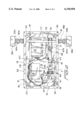
- FIG. 2 is a plan view of the base housing of the apparatus shown with its upper lid removed to display the driver assembly disposed therein;
- FIG. 3 is a side view of the drive assembly illustrating how the pivot arm is moved 90° by the plunger of the pivotally mounted driver;
- FIG. 4A is an exploded view of the coupling assembly used to interconnect the ends of the shaft that is rotatably mounted to the base housing and the legs of the barrier arm;
- FIG. 4B is a perspective view of the coupling assembly illustrated in FIG. 4A shown in assembled form
- FIG. 5 is a perspective view of the drive assembly contained within the base housing, illustrating how the antenna of the radio-controlled switching circuit is threaded through the shaft and drive post that move the barrier arm.
- the parking barrier apparatus 1 of the invention generally comprises a base housing 3, a barrier arm 5, and a drive assembly 7 contained within the base housing 3 for moving the arm 5 between a vertical and horizontal position as indicated in phantom in FIG. 1.
- a radio actuator 9 similar in structure and design to a garage door opener actuates the drive assembly 7 to move the arm 5 into a horizontal, vehicle-admitted position, or a vertical, vehicle-obstructing position as indicated in FIG. 1.
- the apparatus 1 is illustrated as being mounted on the floor of a parking lot, it may also be mounted on the ceiling when the lot is located within a parking garage.
- the base housing 3 is formed from a rectangular enclosure 12 having a floor 14, side walls 16, and a lid 17, all of which are preferably formed from 14 gauge galvanized sheet material.
- the corners and edges of the rectangular enclosure 12 are formed by seam welding to render the enclosure strong and moisture proof.
- Corner moisture barriers 18 are added to prevent water from entering the enclosure from bolt holes 20. Corner barriers 18 also give the enclosure 12 sufficient compressive strength to remain intact should the wheels of an automobile run over it.
- Bolt holes 20 are provided in the corners of the enclosure 12 to accommodate mounting bolts 22 that secure the enclosure 12 to the floor (or ceiling) of a parking lot, as illustrated in FIG. 1. As is shown in FIG.
- an upper flange 23 is provided around the top ends of the side walls 16 for supporting the lid 17, which is attached thereon via "snake eye” screws to discourage unauthorized removal.
- the lid 17 supports, on its upper surface, a solar panel 24 that is covered by a protective plastic sheet 26 preferably formed from Lexan®.
- Solar panel 24 is preferably a 101/2 inch by 171/2 inch 17.1 volt, 0.58 amp unbreakable solar panel. As will be described in more detail hereinafter, the solar panel 24 forms part of the electric power supply 107 of the drive assembly 7.
- the barrier arm 5 includes a frame 30 (which may be made of wood) having a pair of parallel, opposing legs 32a,b.
- a header 34 connects the top ends of the legs 32a,b, and an identifying sign 36 may be mounted in the upper portion of the frame 30 as shown.
- Reinforcing members 38a,b having reflective material 40 are used to both reinforce the frame 30 and to render it more easily visible under low light conditions.
- the bottom ends of the frame legs 32a,b are connected to drive posts 42a,b which in turn are operated by the drive assembly 7 in a manner to be described shortly. In the embodiment illustrated in FIG. 1, such connection may be made by brackets or screws (not shown) that secure the upper ends of the drive posts 42a,b to the bottom ends of the frame legs 32a,b.
- connection may be made by forming the legs 32a,b from a tubular element such as tubular PVC 33a,b (shown in phantom in FIG. 2), and sliding the open ends of such legs over the tubular bodies forming the drive posts 42a,b.
- a tubular element such as tubular PVC 33a,b (shown in phantom in FIG. 2)
- the drive assembly 7 includes a driver 45 having a cylindrical housing 47.
- a reciprocating plunger 49 is extendable from and retractable into the housing 47.
- plunger 49 is connected to a threaded rod 51 which in turn is circumscribed by a drive nut 53.
- Threaded rod 51 is circumscribed by an acme thread to minimize backlash.
- the drive nut 53 is connected to the output shaft of a reversible, DC motor 55 via a gear train (not shown). When the nut 53 is rotated within the housing 47, the threadedly engaged rod will either extend or retract, depending upon the direction of rotation of the nut.
- the driver 45 is a Model No.
- S12-17A8-04CE driver manufactured by Warner Electric, Inc. located in Marengo, Ill. Such a driver has a stroke of 4 inches, a load capacity of 75 pounds, and requires a maximum current of 52/3 amps and is protected by a 6 amp fuse (not shown) contained within housing 47. The 4 inch travel of the plunger 49 is limited by limit switches contained within the housing 47 (also not shown).
- the distal end of the cylindrical housing 47 of the driver 45 is connected the floor panel 14 of the rectangular enclosure 12 by means of a pivoting driver mounting 57.
- Mounting 57 is formed by a yoke bracket 59 connected by screws 60 to the floor panel 14.
- the distal end of the cylindrical housing 47 includes a mounting lug 61.
- a journaling bolt 63 disposed through registering bores (not shown) in the yoke bracket 59 and mounting lugs 61 pivotally connects these components together.
- a pivot arm assembly 65 is disposed at the distal end of the driver 45.
- Pivot arm assembly 65 is formed from a pair of eyebolts 67a,b, the heads 69 of which are rotatably connected to the distal end of the plunger 69 of the driver 45 via bolt 71.
- Bolt 71 is in turn secured in position by way of nut 73 (shown in FIG. 3).
- Drive assembly 7 further includes a mechanism 74 for adjusting the length of the pivot arm assembly 65.
- Mechanism 74 is formed from the threaded ends 75 of the eyebolts 67a,b. Threaded ends 75 are engaged to threaded holes 76 located in rotatable barrier arm shaft 77.
- the shaft 77 is in turn journaled in apertures in the side walls 16 of the rectangular enclosure 12 of base housing 3.
- the pivot arm assembly 65 may be made longer or shorter with respect to the axis of rotation of the shaft 77 by screwing or unscrewing the threaded ends 75 either into or out of the holes 76.
- the provision of such a length-adjustment mechanism 74 for the pivot arm assembly 65 greatly facilitates the assembly of the apparatus 1, since it allows the pivot arm assembly 65 to be quickly and accurately adjusted to a length consistent with a proper 90° stroke of the shaft 77.
- securing nuts 78 are screwed onto the threaded ends 75 to secure the threaded ends of the I-bolts 67a,b into a proper depth in the shaft 77.
- the ends of the rotatable shaft 77 are journaled within apertures 79 in opposing side walls 16 of the enclosure 12 by means of coupling assemblies 80a,b, of which only one (80b) is shown for simplicity.
- the ends 82 of the shaft 77 are threaded as shown.
- the coupling assembly 80b includes a threaded sleeve 84 that screws over the threaded end 82 of the shaft 77 and through the aperture 79.
- Conduit fitting 86 is received within the end of the threaded sleeve 84 in order to prevent moisture from penetrating the interior of the sleeve 84.
- Retaining nuts 88a,b are disposed over the ends of the threaded sleeve 84 and on either side of the aperture 79 to prevent the shaft 77 from moving axially with respect to the side wall 16 of the enclosure 12.
- Retaining nut 88c secures both the conduit fitting 86 and retaining nut 88b in place.
- Spacing nut 90 screws over the threaded end 82 of the shaft 77 and provides space between the side wall 16 of the enclosure 12 and drive post 42b.
- Collar nut 92 is also screwed over the threaded end 82 of the shaft 77 via threaded side bores 94.
- Collar nut 92 includes a central bore 96 for receiving an end of one of the previously-mentioned drive post 42b.
- post 42b is provided with apertures 97a,b which receive the threaded end 82 of the shaft 77.
- a set screw bore 98 is also provided in the collar nut 92 for receiving a set screw (not shown) for clamping the end of the drive post 42b within the collar nut 92.
- the set screw includes a hexagonal recess for receiving an Allen wrench which may be used to over ride the system and lower the barrier in the event of power failure or the loss of the remote control device.
- a washer 100 is disposed between the collar nut 92 and the interface of frame leg 32b.
- coupling assembly 80 includes a frame mounting nut 102 that screws over the distal most portion of the threaded end 82 in order to attach the end of the frame leg 32b onto the drive post 42b.
- Mounting nut 102 is received within a cylindrical recess 103 provided in the end of the frame leg 32b.
- the bottom of the drive post 42b is capped via plastic cap 106 after the distal end of the post is inserted through the collar nut 92.
- the upper ends of both of the drive posts 42a,b are also screwed or otherwise secured onto the frame legs 32a,b so that the frame 30 of the barrier arm 5 is securely mounted onto the drive posts 42a,b.
- the electrical power supply 7 for the motor 55 of the driver 45 includes a battery pack 108 which is connected to the previously described solar panel 24 via a photovoltaic regulator 110.
- the battery pack 108 is a Model No. MP-7-12 volt Yuasa battery manufactured by the Yuasa Battery Company located in Osaka, Japan
- the photovoltaic regulator 110 is preferably a Model "Sun Selector” manufactured by Bobier Electric, Inc. located in Parkersburg, W.V.
- the electric motor 55 of the driver 45 is connected to the output of the battery pack 108 via a radio-controlled switching circuit 112.
- switching circuit 112 is a Model No. WR300/2B radio receiver manufactured by Visonic, Inc.
- the radio actuator 9 (illustrated in FIG. 1) is a Model No. WT-102 transmitter manufactured by the same organization.
- An overload circuit 116 is connected between the battery pack 108 and the motor 55 of the driver 45. This circuit reverses the polarity of the current entering the motor 55 in the event of an overload condition so as to reverse the direction that the driver 45 moves the barrier arm.
- a 6 amp fuse is included within the housing of the driver 45 as further overload protection.
- the antenna 113 of the radio-controlled switching circuit 112 may be strung through the hollow portion of the shaft 77 and the drive post 42b and continuing up into the barrier.
- the operation of the apparatus 1 may best be understood with respect to FIGS. 1 and 2.
- a button on the radio actuator 9 which is received by the antenna 113 of the radio-controlled switching circuit 112.
- the actuation of the circuit 112 connects the battery pack 108 of the electrical power supply 107 to the motor 55 of the driver 45.
- the barrier arm 5 of the apparatus 1 is in the vertical position illustrated in FIG. 1, and the reciprocating plunger 49 of the driver 45 is retracted into the position illustrated in FIG. 3.
- motor 55 rotates the drive nut 53 of the driver 45 to extend the reciprocating plunger 49 into the position illustrated in phantom in order to move the barrier arm 5 from a vertical, upright position 90° into the horizontal position illustrated in phantom.
- the pivoting driver mounting 57 allows the driver 45 to pivot downwardly toward the floor panel 14 and then upwardly a distance d while the plunger 49 rotates the shaft 77 90° via pivot arm assembly 65.
- the linear movement of the plunger 49 of the driver 45 is smoothly converted into a 90° circular movement by the action of the pivoting mounting 57 in allowing the driver 45 to pivot up and down the distance "d," similar to the action of pneumatic door closer.
- a limit switch (not shown) is tripped within the driver 45, disconnecting the motor 55 from the output of the battery pack 108 and signaling the radio-controlled switching circuit 112 that the movement cycle of the barrier arm 5 has been completed.
- the operator of the vehicle for whom the space has been reserved parks his vehicle into the space 120.
- the radio-controlled switching circuit 112 again closes a circuit between the motor 55 and the battery pack 108, but at an opposite polarity so that the direction of the rotation of the electric motor 55 is reversed.
Abstract
Description
Claims (26)
Priority Applications (1)
| Application Number | Priority Date | Filing Date | Title |
|---|---|---|---|
| US09/334,685 US6150958A (en) | 1999-06-17 | 1999-06-17 | Remote controlled parking barrier apparatus |
Applications Claiming Priority (1)
| Application Number | Priority Date | Filing Date | Title |
|---|---|---|---|
| US09/334,685 US6150958A (en) | 1999-06-17 | 1999-06-17 | Remote controlled parking barrier apparatus |
Publications (1)
| Publication Number | Publication Date |
|---|---|
| US6150958A true US6150958A (en) | 2000-11-21 |
Family
ID=23308338
Family Applications (1)
| Application Number | Title | Priority Date | Filing Date |
|---|---|---|---|
| US09/334,685 Expired - Fee Related US6150958A (en) | 1999-06-17 | 1999-06-17 | Remote controlled parking barrier apparatus |
Country Status (1)
| Country | Link |
|---|---|
| US (1) | US6150958A (en) |
Cited By (21)
| Publication number | Priority date | Publication date | Assignee | Title |
|---|---|---|---|---|
| FR2824852A1 (en) * | 2001-05-15 | 2002-11-22 | Claude Boujard | Automatic barrier for vehicle parking space, comprises gate articulated to base fixed to ground and pivoting between vertical active position and horizontal retracted position under remote control |
| US6619629B1 (en) * | 1998-07-21 | 2003-09-16 | Anthony Boswell | Guide device for vehicle parking |
| US6709190B1 (en) * | 2002-09-16 | 2004-03-23 | James O. Partin | Double-cross barricade |
| US20040165949A1 (en) * | 2002-12-10 | 2004-08-26 | Rittenhouse James M. | Remote controlled parking barrier apparatus |
| US20050102872A1 (en) * | 2003-11-19 | 2005-05-19 | Marc-Andre Seguin | Traffic-signalling system |
| GB2409228A (en) * | 2003-11-21 | 2005-06-22 | Blake Uk Ltd | Device for restricting vehicle access |
| US20050237225A1 (en) * | 2004-04-06 | 2005-10-27 | Mongkol Jesadanont | Apparatus and method of finding an unoccupied parking space in a parking lot |
| US20070085067A1 (en) * | 2005-10-18 | 2007-04-19 | Lewis John R | Gated parking corral |
| WO2009019171A1 (en) * | 2007-08-07 | 2009-02-12 | Lorenzo Cavalieri Ducati | Parking dissuader |
| AU2009101341B4 (en) * | 2009-12-07 | 2011-01-06 | Henderson, David Macalister Mr | Car Park Reserving Apparatus |
| US20120044046A1 (en) * | 2010-08-18 | 2012-02-23 | Al-Jafar Ahmed I S I | Remote Control Parking Barrier |
| US20130071182A1 (en) * | 2011-09-21 | 2013-03-21 | Hy-Security Gate, Inc. | Dual arm fortified barrier assembly |
| US8678701B1 (en) | 2013-05-28 | 2014-03-25 | Farraj J. A. Aldasem | System for remote control of retractable, ground-based vehicle barriers |
| US8794866B2 (en) | 2012-04-25 | 2014-08-05 | Taras Petryshyn | Collapsible barricade apparatus |
| FR3010421A1 (en) * | 2013-09-06 | 2015-03-13 | Assystem France | CIRCULATION REGULATION DEVICE. |
| NL2013458B1 (en) * | 2014-09-11 | 2016-09-28 | Nedflex Holding B V | Tramline security device. |
| US9464392B2 (en) * | 2014-11-21 | 2016-10-11 | Rudor Teich | Battery operated parking barrier |
| US10094081B1 (en) | 2015-11-09 | 2018-10-09 | James G. Gill | Parking space holder |
| US20200279196A1 (en) * | 2018-01-10 | 2020-09-03 | Bayerische Motoren Werke Aktiengesellschaft | Parking Space Lock and System and Method for Providing Parking Service |
| US11037448B2 (en) * | 2014-02-20 | 2021-06-15 | MyPark, Corp. | Intelligent parking system |
| US11263907B2 (en) * | 2018-10-05 | 2022-03-01 | Tyler Witten | System including a user interface application for reserving a parking space |
Citations (12)
| Publication number | Priority date | Publication date | Assignee | Title |
|---|---|---|---|---|
| US3673734A (en) * | 1970-12-02 | 1972-07-04 | Leonard Goldberg | Parking field security device |
| US3748782A (en) * | 1972-11-14 | 1973-07-31 | D Reynolds | Traffic flow controller |
| US3849936A (en) * | 1973-03-12 | 1974-11-26 | V Geraci | Parking stall barrier |
| JPS5433341A (en) * | 1977-08-19 | 1979-03-12 | Shin Meiwa Ind Co Ltd | Unattended parking lot controller |
| US4713910A (en) * | 1984-12-12 | 1987-12-22 | ARMO Gesellschaft fur Bauelemente, Bau - und Wohnbedarf GmbH | Barrier post for parking lots and passageways |
| US4879554A (en) * | 1988-03-11 | 1989-11-07 | Diaz Silveira Jorge | Barrier assembly for a parking space |
| US4894654A (en) * | 1988-08-19 | 1990-01-16 | Serenbetz George B | Method and apparatus for reserving parking spaces and/or security |
| US4901071A (en) * | 1989-03-30 | 1990-02-13 | Fletcher Frank I | Portable reserved parking alarm system |
| US4934097A (en) * | 1987-04-09 | 1990-06-19 | Armo Gesellschaft fur Baulemente, Bau-und Wohnbedarf GmbH | Barrier post free of jamming points |
| EP0433052A1 (en) * | 1989-12-12 | 1991-06-19 | International Business Machines Corporation | Thermally dissipated soldering flux and method of use |
| US5438799A (en) * | 1992-07-28 | 1995-08-08 | Annie C. Kerjan | Arrangement with a device pivoting between two positions such as a barrier arrangement swinging between a position forbidding the access to a reserved area and an access clearing position |
| US5711110A (en) * | 1996-08-23 | 1998-01-27 | Williams; J. Marlis | Vehicle parking barrier |
-
1999
- 1999-06-17 US US09/334,685 patent/US6150958A/en not_active Expired - Fee Related
Patent Citations (12)
| Publication number | Priority date | Publication date | Assignee | Title |
|---|---|---|---|---|
| US3673734A (en) * | 1970-12-02 | 1972-07-04 | Leonard Goldberg | Parking field security device |
| US3748782A (en) * | 1972-11-14 | 1973-07-31 | D Reynolds | Traffic flow controller |
| US3849936A (en) * | 1973-03-12 | 1974-11-26 | V Geraci | Parking stall barrier |
| JPS5433341A (en) * | 1977-08-19 | 1979-03-12 | Shin Meiwa Ind Co Ltd | Unattended parking lot controller |
| US4713910A (en) * | 1984-12-12 | 1987-12-22 | ARMO Gesellschaft fur Bauelemente, Bau - und Wohnbedarf GmbH | Barrier post for parking lots and passageways |
| US4934097A (en) * | 1987-04-09 | 1990-06-19 | Armo Gesellschaft fur Baulemente, Bau-und Wohnbedarf GmbH | Barrier post free of jamming points |
| US4879554A (en) * | 1988-03-11 | 1989-11-07 | Diaz Silveira Jorge | Barrier assembly for a parking space |
| US4894654A (en) * | 1988-08-19 | 1990-01-16 | Serenbetz George B | Method and apparatus for reserving parking spaces and/or security |
| US4901071A (en) * | 1989-03-30 | 1990-02-13 | Fletcher Frank I | Portable reserved parking alarm system |
| EP0433052A1 (en) * | 1989-12-12 | 1991-06-19 | International Business Machines Corporation | Thermally dissipated soldering flux and method of use |
| US5438799A (en) * | 1992-07-28 | 1995-08-08 | Annie C. Kerjan | Arrangement with a device pivoting between two positions such as a barrier arrangement swinging between a position forbidding the access to a reserved area and an access clearing position |
| US5711110A (en) * | 1996-08-23 | 1998-01-27 | Williams; J. Marlis | Vehicle parking barrier |
Cited By (30)
| Publication number | Priority date | Publication date | Assignee | Title |
|---|---|---|---|---|
| US6619629B1 (en) * | 1998-07-21 | 2003-09-16 | Anthony Boswell | Guide device for vehicle parking |
| FR2824852A1 (en) * | 2001-05-15 | 2002-11-22 | Claude Boujard | Automatic barrier for vehicle parking space, comprises gate articulated to base fixed to ground and pivoting between vertical active position and horizontal retracted position under remote control |
| US6709190B1 (en) * | 2002-09-16 | 2004-03-23 | James O. Partin | Double-cross barricade |
| US20040165949A1 (en) * | 2002-12-10 | 2004-08-26 | Rittenhouse James M. | Remote controlled parking barrier apparatus |
| US7001099B2 (en) * | 2002-12-10 | 2006-02-21 | Designated Parking Corp. | Remote controlled parking barrier apparatus |
| US20050102872A1 (en) * | 2003-11-19 | 2005-05-19 | Marc-Andre Seguin | Traffic-signalling system |
| US7098807B2 (en) * | 2003-11-19 | 2006-08-29 | 9076-0935 Quebec Inc. | Traffic-signaling system |
| GB2409228B (en) * | 2003-11-21 | 2007-05-09 | Blake Uk Ltd | Device for restricting access |
| GB2409228A (en) * | 2003-11-21 | 2005-06-22 | Blake Uk Ltd | Device for restricting vehicle access |
| US20050237225A1 (en) * | 2004-04-06 | 2005-10-27 | Mongkol Jesadanont | Apparatus and method of finding an unoccupied parking space in a parking lot |
| US7106214B2 (en) * | 2004-04-06 | 2006-09-12 | Mongkol Jesadanont | Apparatus and method of finding an unoccupied parking space in a parking lot |
| US20070085067A1 (en) * | 2005-10-18 | 2007-04-19 | Lewis John R | Gated parking corral |
| WO2009019171A1 (en) * | 2007-08-07 | 2009-02-12 | Lorenzo Cavalieri Ducati | Parking dissuader |
| AU2009101341B4 (en) * | 2009-12-07 | 2011-01-06 | Henderson, David Macalister Mr | Car Park Reserving Apparatus |
| US20120044046A1 (en) * | 2010-08-18 | 2012-02-23 | Al-Jafar Ahmed I S I | Remote Control Parking Barrier |
| US8618906B2 (en) * | 2010-08-18 | 2013-12-31 | Ahmed I.S.I. Al-Jafar | Remote control parking barrier |
| US20160002870A1 (en) * | 2011-09-21 | 2016-01-07 | Hy-Security Gate, Inc. | Dual arm fortified barrier assembly |
| US20130071182A1 (en) * | 2011-09-21 | 2013-03-21 | Hy-Security Gate, Inc. | Dual arm fortified barrier assembly |
| US9822501B2 (en) * | 2011-09-21 | 2017-11-21 | Oculus Vr, Llc | Dual arm fortified barrier assembly |
| EP3346055A1 (en) | 2012-04-25 | 2018-07-11 | Petryshyn, Taras | Collapsible barricade apparatus |
| US8794866B2 (en) | 2012-04-25 | 2014-08-05 | Taras Petryshyn | Collapsible barricade apparatus |
| US8678701B1 (en) | 2013-05-28 | 2014-03-25 | Farraj J. A. Aldasem | System for remote control of retractable, ground-based vehicle barriers |
| FR3010421A1 (en) * | 2013-09-06 | 2015-03-13 | Assystem France | CIRCULATION REGULATION DEVICE. |
| US11037448B2 (en) * | 2014-02-20 | 2021-06-15 | MyPark, Corp. | Intelligent parking system |
| NL2013458B1 (en) * | 2014-09-11 | 2016-09-28 | Nedflex Holding B V | Tramline security device. |
| US9464392B2 (en) * | 2014-11-21 | 2016-10-11 | Rudor Teich | Battery operated parking barrier |
| US10094081B1 (en) | 2015-11-09 | 2018-10-09 | James G. Gill | Parking space holder |
| US20200279196A1 (en) * | 2018-01-10 | 2020-09-03 | Bayerische Motoren Werke Aktiengesellschaft | Parking Space Lock and System and Method for Providing Parking Service |
| US11790283B2 (en) * | 2018-01-10 | 2023-10-17 | Bayerische Motoren Werke Aktiengesellschaft | Parking space lock and system and method for providing parking service |
| US11263907B2 (en) * | 2018-10-05 | 2022-03-01 | Tyler Witten | System including a user interface application for reserving a parking space |
Similar Documents
| Publication | Publication Date | Title |
|---|---|---|
| US6150958A (en) | Remote controlled parking barrier apparatus | |
| US4638597A (en) | Modular automatic gate opener | |
| US5009542A (en) | Traffic barrier gate | |
| US7533494B2 (en) | Railroad grade crossing assembly | |
| US4658543A (en) | Swinging lift gate | |
| US4934097A (en) | Barrier post free of jamming points | |
| US8618906B2 (en) | Remote control parking barrier | |
| US4416085A (en) | Automatic gate opener | |
| US4333268A (en) | Energy saving electrically actuated barrier gate control means operable from solar energy | |
| US5075834A (en) | Retractable light fixture | |
| CN108571249A (en) | Power swing door drives actuator | |
| US5440838A (en) | Motorized vertical lift gate | |
| US6135190A (en) | Chain barrier | |
| US7918191B2 (en) | Remotely operable gated chute for livestock | |
| US4916859A (en) | Assault-resistant gate | |
| US7356966B2 (en) | Railroad grade crossing assembly | |
| GB2245296A (en) | Parking post | |
| CN211646133U (en) | Mechanical garage alarm system | |
| US20040182005A1 (en) | Electromechanical barrier | |
| KR20070051992A (en) | Traffic gate for parking lot | |
| CN115492445A (en) | Electric power iron tower protector | |
| WO1991009176A1 (en) | Parking space barrier | |
| CN210368742U (en) | Suspension type self-adaptation intelligence parking stall management device | |
| WO1997041307A1 (en) | Access control device | |
| CA2701400C (en) | Remotely operable gated chute for livestock |
Legal Events
| Date | Code | Title | Description |
|---|---|---|---|
| AS | Assignment |
Owner name: CRIMINALISTICS, INC., WASHINGTON Free format text: ASSIGNMENT OF ASSIGNORS INTEREST;ASSIGNOR:WORSHAM, ROBERT J.;REEL/FRAME:010056/0778 Effective date: 19990614 |
|
| FPAY | Fee payment |
Year of fee payment: 4 |
|
| FEPP | Fee payment procedure |
Free format text: PETITION RELATED TO MAINTENANCE FEES FILED (ORIGINAL EVENT CODE: PMFP); ENTITY STATUS OF PATENT OWNER: SMALL ENTITY |
|
| REMI | Maintenance fee reminder mailed | ||
| REIN | Reinstatement after maintenance fee payment confirmed | ||
| FEPP | Fee payment procedure |
Free format text: PETITION RELATED TO MAINTENANCE FEES GRANTED (ORIGINAL EVENT CODE: PMFG); ENTITY STATUS OF PATENT OWNER: SMALL ENTITY |
|
| FPAY | Fee payment |
Year of fee payment: 8 |
|
| SULP | Surcharge for late payment | ||
| FP | Lapsed due to failure to pay maintenance fee |
Effective date: 20081121 |
|
| PRDP | Patent reinstated due to the acceptance of a late maintenance fee |
Effective date: 20090225 |
|
| REMI | Maintenance fee reminder mailed | ||
| LAPS | Lapse for failure to pay maintenance fees | ||
| STCH | Information on status: patent discontinuation |
Free format text: PATENT EXPIRED DUE TO NONPAYMENT OF MAINTENANCE FEES UNDER 37 CFR 1.362 |
|
| FP | Lapsed due to failure to pay maintenance fee |
Effective date: 20121121 |