US6151162A - Rear projection screen - Google Patents
Rear projection screen Download PDFInfo
- Publication number
- US6151162A US6151162A US09/210,419 US21041998A US6151162A US 6151162 A US6151162 A US 6151162A US 21041998 A US21041998 A US 21041998A US 6151162 A US6151162 A US 6151162A
- Authority
- US
- United States
- Prior art keywords
- fresnel
- screen
- projection screen
- facets
- plane
- Prior art date
- Legal status (The legal status is an assumption and is not a legal conclusion. Google has not performed a legal analysis and makes no representation as to the accuracy of the status listed.)
- Expired - Fee Related
Links
- 238000005286 illumination Methods 0.000 claims description 2
- 239000000758 substrate Substances 0.000 description 8
- 239000000463 material Substances 0.000 description 6
- 239000011888 foil Substances 0.000 description 5
- 230000015572 biosynthetic process Effects 0.000 description 4
- 239000003795 chemical substances by application Substances 0.000 description 3
- 239000011358 absorbing material Substances 0.000 description 2
- 230000007423 decrease Effects 0.000 description 2
- 238000009825 accumulation Methods 0.000 description 1
- 239000003292 glue Substances 0.000 description 1
- 230000031700 light absorption Effects 0.000 description 1
- 239000007788 liquid Substances 0.000 description 1
- 239000000203 mixture Substances 0.000 description 1
Images
Classifications
-
- G—PHYSICS
- G03—PHOTOGRAPHY; CINEMATOGRAPHY; ANALOGOUS TECHNIQUES USING WAVES OTHER THAN OPTICAL WAVES; ELECTROGRAPHY; HOLOGRAPHY
- G03B—APPARATUS OR ARRANGEMENTS FOR TAKING PHOTOGRAPHS OR FOR PROJECTING OR VIEWING THEM; APPARATUS OR ARRANGEMENTS EMPLOYING ANALOGOUS TECHNIQUES USING WAVES OTHER THAN OPTICAL WAVES; ACCESSORIES THEREFOR
- G03B21/00—Projectors or projection-type viewers; Accessories therefor
- G03B21/54—Accessories
- G03B21/56—Projection screens
- G03B21/60—Projection screens characterised by the nature of the surface
- G03B21/62—Translucent screens
- G03B21/625—Lenticular translucent screens
Definitions
- the invention relates to a rear projection screen comprising a first plate, a first side of which has a lenticular structure, and a second plate, a first side of which has a Fresnel structure with a plurality of Fresnel facets enclosing an angle ⁇ with the plane of the screen, a second side of the first plate and the first side of the second plate facing each other.
- the invention also relates to a rear projection system comprising projection modules which can be stacked and are provided with such a rear projection screen.
- a projection screen of the type described in the opening paragraph is known from, for example U.S. Pat. No. 4,919,518.
- This patent describes a projection screen with a Fresnel lens, a prism structure and a lenticular structure. The light to be projected is incident on the Fresnel structure and leaves the screen via the lenticular structure.
- An important requirement for such a projection screen is that it has a sufficient stability.
- a sufficient stability can be realized in different manners.
- a first possibility is to render the lens structures, in other words, the Fresnel structure and the lenticular structure, sufficiently rigid by themselves by choosing the lens plates to be thick enough.
- this has the drawback that reflections in a relatively thick plate give rise to ghost images.
- Another possibility is to provide a relatively thin lens plate, such as, for example a lens foil, on a separate substrate.
- a relatively thin lens plate such as, for example a lens foil
- This has the drawback that extra surfaces are created in this way, on which unwanted reflections will occur.
- there will be loss of light due to light absorption in the substrate.
- the risk of accumulation of moisture between the surface of the unstable lens structure and the surface of the substrate will be considerably large as a result of the air humidity.
- a further drawback of the known projection screens notably in the case of a projection screen comprising stacked modules, is that the lens structures are exactly equally large and that it is impossible to fix them to each other without disturbing the image at the edges of a module.
- the Fresnel facets are divided into a first part which encloses an angle ⁇ with the plane of the screen, and a second, contiguous part which is substantially parallel to the plane of the screen, the second parts of the Fresnel lens being fixed to the second side of the first plate.
- the present invention is based on the recognition that given parts of the Fresnel structure do not contribute to the formation of the image. Signal light rays which are incident on the screen will be refracted on the interface between the air and the screen. In this way, a part of each Fresnel facet will not receive light and function as a blind space. This blind space per facet becomes larger as the distance between the facet and the center of the screen becomes larger. At a given value of the distance to the center of the screen, the size of the blind space depends on the focal length.
- the present invention proposes to truncate the facets of the Fresnel structure, with the truncated part approximately corresponding in size to the blind space. A further advantage of this solution is that the Fresnel structure is less deep and thus becomes less vulnerable because most projecting parts are truncated.
- the Fresnel structure may be a linear or a circular structure.
- a preferred embodiment of the projection screen according to the invention is characterized in that the Fresnel lens is fixed to the first plate by means of a black fixation agent.
- these parts do not pass light which must contribute to the formation of the image, they may be provided with a light-absorbing material. These light-absorbing parts absorb a part of the ambient light. In this way, the image contrast on the projection screen can be enhanced without obstructing signal light.
- the projection system described may be used to great advantage in an image projection system having projection modules which can be stacked.
- the circumference of the lenticular structure and the Fresnel structure are equal to each other so that there is no space to fix the components of the screen to each other without detrimentally influencing the image.
- This problem is solved by making use of a Fresnel structure with truncated Fresnel facets.
- the lens structures are fixed to each other at positions which are distributed on the lens surfaces.
- FIG. 1 shows an embodiment of a conventional projection screen
- FIG. 2(a) shows an embodiment of a conventional Fresnel structure
- FIG. 2(b) shows an embodiment of a Fresnel structure for use in a projection screen according to the invention
- FIG. 2(c) illustrates how blind spaces are produced
- FIG. 3 is a side elevation of an embodiment of a projection screen according to the invention.
- FIG. 4 shows an embodiment of a projection system with projection modules which can be stacked and with a projection screen according to the invention.
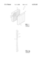
- the prior art projection screen 1 shown in FIG. 1 comprises a plate 3, one side of which has a lenticular structure 5 facing the viewer's space during use.
- the projection screen 1 further comprises a Fresnel structure 4 facing the plate 3 during use.
- the Fresnel structure consists of Fresnel facets 7 and riser edges 9.
- the Fresnel structure shown in FIG. 1 is circular. In the present invention, the Fresnel structure may be linear or circular.
- the lenticular structure is not limited to that shown in FIG. 1 but may also represent other structures having for their function to spread the signal light into the viewer's space.
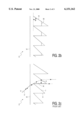
- FIG. 2(a) shows an embodiment of a conventional Fresnel structure.
- the riser edges 9 become larger towards the ends of the projection screen because the Fresnel facets 7 become steeper. Consequently, the screen will be relatively vulnerable towards the ends.
- FIG. 2(c) illustrates how blind spaces are produced in a conventional Fresnel structure.
- Light rays which are incident on the interface 14 between the air and the screen are refracted a first time on this interface.
- a ray b passes through the Fresnel lens and reaches a Fresnel facet 7 on which the light ray is again refracted.
- the light ray b' is refracted on the interface 14 and will undergo a second refraction on the facet located under the facet on which the light ray b was refracted.
- a part 16 of each Fresnel facet will not receive signal light so that it will not contribute to the formation of the image.
- the height d of this part 16 becomes larger as the distance between the Fresnel facets and the center of the screen becomes larger.
- the size of the blind space depends on the focal length of the Fresnel structure.
- FIG. 2(b) shows a part of an embodiment of a Fresnel structure as used in a projection screen according to the invention.
- the Fresnel facets 7 are divided into a first part 11 which encloses an angle ⁇ with the plane of the screen and a second, contiguous part 13 which is substantially parallel to the plane of the screen.
- the size of the second part is determined by the size of the blind space.
- the present invention proposes to truncate the Fresnel facets. Due to this measure, substantially no signal light is lost.
- the Fresnel structure and the lenticular structure can be fixed directly to each other. An extra substrate which is normally used to ensure some stability can therefore be dispensed with.
- the reason of using a thin Fresnel structure may be the creation of ghost images in a rigid Fresnel structure having a minimal thickness.
- the Fresnel structure may be thin enough, for example thinner than 0.5 mm, the ghost images will be located close enough together so that they can no longer be distinguished by the human eye.
- Such a foil is not rigid enough of itself to ensure a sufficient stability.
- the Fresnel structure may be, for example a rigid structure, whereas the lenticular structure is a thin, insufficiently stable structure.
- use of the invention yields a stable combination.
- the present invention includes an additional aspect providing a solution to the following problem.
- the current image projectors whose signal light is incident on the projection screen supply beams having an intensity which decreases towards the outer side of the beam. This means that there will be less signal light at the edges of the projection screen, resulting in a decrease of the contrast. Moreover, the reflections of the ambient light are greatest at the edges of the projection screen because the Fresnel facets are steeper there. These two aspects cause the contrast at the edges of the projection screen to be very low.
- a light-absorbing fixation agent 17 such as, for example black glue is provided on the truncated facets of the Fresnel structure.
- the contrast can be enhanced considerably. Since the blind spaces and hence the truncated facets are largest at the edges of the screen, the reflection is maximally reduced at the areas where the brightness is relatively low.
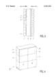
- FIG. 3 shows an embodiment of a projection screen according to the invention.
- the Fresnel structure 4 and the lenticular structure 5 are fixed to each other by means of the truncated facets 13 and by means of a fixation agent 17 which is preferably light-absorbing.
- the lenticular structure 5 is the rigid structure.
- This structure is present on a substrate 21 which, as usual, is provided with a diffusing material 19. In the embodiment shown, this is a strip.
- the diffusing material 19 may be alternatively spread on the entire substrate. The lenticular structure and the diffusing material ensure that the signal light is distributed optimally in the viewer's space.
- the strip of diffusing material is relatively thin in this case and is situated relatively close to the lenticular structure so that a high resolution can be realized.
- the diffusing material may also be distributed, for example in the lenticular structure itself.
- a second strip of diffusing material (not shown), separated from the first strip, may be present in the substrate. Speckle can be reduced in this way.
- the projection screen according to the invention may be used to great advantage in an image projection system having modules which can be stacked.
- An embodiment of such an image projection system 23 is shown in FIG. 4.
- the system shown in this Figure comprises four modules 25, 27, 29 and 31.
- the combination comprises two columns and two rows.
- Each module comprises a projection screen 33, 35, 37, 39 according to the invention.
- the image on the edges of the projection screens is now no longer influenced detrimentally by fixing the Fresnel structure and the lenticular structure to each other, so that the images of two contiguous screens blend with each other.
- the reason therefor is that the Fresnel structure and the lenticular structure are fixed to each other in this case at points which are distributed across the entire screen surface. Moreover, these points of fixation do not disturb the image at all because they coincide with the blind spaces of the Fresnel structure.
- the present invention thus proposes to use a Fresnel structure with truncated Fresnel facets in an image projection screen.
- the Fresnel facets face away from the illumination side of the screen.
- the Fresnel lens yields the smallest loss of signal light.
- the Fresnel structure and a lenticular structure are fixed to each other by means of the truncated facets. In this way, a rigid structure having a sufficient stability is realized, while the projected image is not affected thereby.
- the size of the truncated facets is substantially equal to the size of the blind spaces in the Fresnel structure so that substantially no signal light is lost.
- the image projection screen remains well usable on its edges. By providing the truncated facets with a light-absorbing material, the image contrast on the screen is also enhanced.
Abstract
A rear projection screen (1) comprising a lenticular structure (5) and a Fresnel structure (4). The Fresnel structure (4) has riser edges (9) and Fresnel facets (7). The Fresnel facets (7) are divided into two parts. The first part (11) encloses an angle ψ with the plane of the projection screen. The second part (13) is substantially parallel to the plane of the screen. The Fresnel structure (4) and the lenticular structure (5) are fixed to each other at the second parts of the Fresnel structure.
Description
The invention relates to a rear projection screen comprising a first plate, a first side of which has a lenticular structure, and a second plate, a first side of which has a Fresnel structure with a plurality of Fresnel facets enclosing an angle ψ with the plane of the screen, a second side of the first plate and the first side of the second plate facing each other.
The invention also relates to a rear projection system comprising projection modules which can be stacked and are provided with such a rear projection screen.
A projection screen of the type described in the opening paragraph is known from, for example U.S. Pat. No. 4,919,518. This patent describes a projection screen with a Fresnel lens, a prism structure and a lenticular structure. The light to be projected is incident on the Fresnel structure and leaves the screen via the lenticular structure. An important requirement for such a projection screen is that it has a sufficient stability.
A sufficient stability can be realized in different manners. A first possibility is to render the lens structures, in other words, the Fresnel structure and the lenticular structure, sufficiently rigid by themselves by choosing the lens plates to be thick enough. However, this has the drawback that reflections in a relatively thick plate give rise to ghost images.
Another possibility is to provide a relatively thin lens plate, such as, for example a lens foil, on a separate substrate. This has the drawback that extra surfaces are created in this way, on which unwanted reflections will occur. Moreover, there will be loss of light due to light absorption in the substrate. Furthermore, the risk of accumulation of moisture between the surface of the unstable lens structure and the surface of the substrate will be considerably large as a result of the air humidity.
A further drawback of the known projection screens, notably in the case of a projection screen comprising stacked modules, is that the lens structures are exactly equally large and that it is impossible to fix them to each other without disturbing the image at the edges of a module.
It is an object of the present invention to provide a projection screen in which the combination of the lens structures is sufficiently stable and in which unwanted reflections and reduced efficiency are obviated.
To this end, the Fresnel facets are divided into a first part which encloses an angle ψ with the plane of the screen, and a second, contiguous part which is substantially parallel to the plane of the screen, the second parts of the Fresnel lens being fixed to the second side of the first plate.
Due to this measure, it is possible to fix the Fresnel structure and the lenticular structure directly to each other. A substrate for ensuring stability will then be superfluous. This has its advantages, both for a Fresnel foil and a rigid lenticular structure and for a rigid Fresnel structure and a lenticular structure in the form of a foil. Moreover, no light is lost because the truncated facets of the Fresnel structure coincide with those parts of the Fresnel structure where no projection light passes, for the following reason.
The present invention is based on the recognition that given parts of the Fresnel structure do not contribute to the formation of the image. Signal light rays which are incident on the screen will be refracted on the interface between the air and the screen. In this way, a part of each Fresnel facet will not receive light and function as a blind space. This blind space per facet becomes larger as the distance between the facet and the center of the screen becomes larger. At a given value of the distance to the center of the screen, the size of the blind space depends on the focal length. The present invention proposes to truncate the facets of the Fresnel structure, with the truncated part approximately corresponding in size to the blind space. A further advantage of this solution is that the Fresnel structure is less deep and thus becomes less vulnerable because most projecting parts are truncated.
The Fresnel structure may be a linear or a circular structure.
It is to be noted that there are projection screens of one piece in which the Fresnel structure faces the projector and the lenticular structure faces the viewer. In this way, there are no surfaces causing extra reflections, but a Fresnel structure facing the projector gives rise to a considerable loss of light. In fact, a large part of the signal light is incident on the riser edges of the Fresnel structure and is lost instead of contributing to the formation of the image.
It is further to be noted that French patent specification 2 737 581 to which U.S. Pat. No. 5,751,387 corresponds describes a Fresnel lens with truncated Fresnel facets. This Fresnel lens is used in combination with a liquid crystalline display panel and its structured surface faces the incident, unmodulated light beam. It is used for guiding the incident light as a parallel beam towards the display panel. The black strips are used to suppress ghost images.
A preferred embodiment of the projection screen according to the invention is characterized in that the Fresnel lens is fixed to the first plate by means of a black fixation agent.
Since these parts do not pass light which must contribute to the formation of the image, they may be provided with a light-absorbing material. These light-absorbing parts absorb a part of the ambient light. In this way, the image contrast on the projection screen can be enhanced without obstructing signal light.
The projection system described may be used to great advantage in an image projection system having projection modules which can be stacked. In such modules, the circumference of the lenticular structure and the Fresnel structure are equal to each other so that there is no space to fix the components of the screen to each other without detrimentally influencing the image. This problem is solved by making use of a Fresnel structure with truncated Fresnel facets. The lens structures are fixed to each other at positions which are distributed on the lens surfaces.
These and other aspects of the invention are apparent from and will be elucidated with reference to the embodiments described hereinafter.
FIG. 1 shows an embodiment of a conventional projection screen;
FIG. 2(a) shows an embodiment of a conventional Fresnel structure;
FIG. 2(b) shows an embodiment of a Fresnel structure for use in a projection screen according to the invention;
FIG. 2(c) illustrates how blind spaces are produced;
FIG. 3 is a side elevation of an embodiment of a projection screen according to the invention, and
FIG. 4 shows an embodiment of a projection system with projection modules which can be stacked and with a projection screen according to the invention.
The prior art projection screen 1 shown in FIG. 1 comprises a plate 3, one side of which has a lenticular structure 5 facing the viewer's space during use. The projection screen 1 further comprises a Fresnel structure 4 facing the plate 3 during use. The Fresnel structure consists of Fresnel facets 7 and riser edges 9. The Fresnel structure shown in FIG. 1 is circular. In the present invention, the Fresnel structure may be linear or circular. The lenticular structure is not limited to that shown in FIG. 1 but may also represent other structures having for their function to spread the signal light into the viewer's space.
FIG. 2(a) shows an embodiment of a conventional Fresnel structure. The riser edges 9 become larger towards the ends of the projection screen because the Fresnel facets 7 become steeper. Consequently, the screen will be relatively vulnerable towards the ends.
FIG. 2(c) illustrates how blind spaces are produced in a conventional Fresnel structure. Light rays which are incident on the interface 14 between the air and the screen are refracted a first time on this interface. A ray b passes through the Fresnel lens and reaches a Fresnel facet 7 on which the light ray is again refracted. The light ray b' is refracted on the interface 14 and will undergo a second refraction on the facet located under the facet on which the light ray b was refracted. As a result, a part 16 of each Fresnel facet will not receive signal light so that it will not contribute to the formation of the image. The height d of this part 16 becomes larger as the distance between the Fresnel facets and the center of the screen becomes larger. For a given value of the distance to the center of the screen, the size of the blind space depends on the focal length of the Fresnel structure.
FIG. 2(b) shows a part of an embodiment of a Fresnel structure as used in a projection screen according to the invention. In the Fresnel structure of the projection screen according to the invention, the Fresnel facets 7 are divided into a first part 11 which encloses an angle ψ with the plane of the screen and a second, contiguous part 13 which is substantially parallel to the plane of the screen. The size of the second part is determined by the size of the blind space.
The present invention proposes to truncate the Fresnel facets. Due to this measure, substantially no signal light is lost. By means of the truncated facets, the Fresnel structure and the lenticular structure can be fixed directly to each other. An extra substrate which is normally used to ensure some stability can therefore be dispensed with.
The reason of using a thin Fresnel structure, for example in the form of a foil, may be the creation of ghost images in a rigid Fresnel structure having a minimal thickness. By choosing the Fresnel structure to be thin enough, for example thinner than 0.5 mm, the ghost images will be located close enough together so that they can no longer be distinguished by the human eye. Such a foil is not rigid enough of itself to ensure a sufficient stability.
The Fresnel structure may be, for example a rigid structure, whereas the lenticular structure is a thin, insufficiently stable structure. Here, too, use of the invention yields a stable combination.
The present invention includes an additional aspect providing a solution to the following problem. The current image projectors whose signal light is incident on the projection screen supply beams having an intensity which decreases towards the outer side of the beam. This means that there will be less signal light at the edges of the projection screen, resulting in a decrease of the contrast. Moreover, the reflections of the ambient light are greatest at the edges of the projection screen because the Fresnel facets are steeper there. These two aspects cause the contrast at the edges of the projection screen to be very low.
In the projection screen according to the invention, a light-absorbing fixation agent 17 such as, for example black glue is provided on the truncated facets of the Fresnel structure. In this way, the contrast can be enhanced considerably. Since the blind spaces and hence the truncated facets are largest at the edges of the screen, the reflection is maximally reduced at the areas where the brightness is relatively low.
FIG. 3 shows an embodiment of a projection screen according to the invention. The Fresnel structure 4 and the lenticular structure 5 are fixed to each other by means of the truncated facets 13 and by means of a fixation agent 17 which is preferably light-absorbing. In the embodiment shown, the lenticular structure 5 is the rigid structure. This structure is present on a substrate 21 which, as usual, is provided with a diffusing material 19. In the embodiment shown, this is a strip. The diffusing material 19 may be alternatively spread on the entire substrate. The lenticular structure and the diffusing material ensure that the signal light is distributed optimally in the viewer's space. The strip of diffusing material is relatively thin in this case and is situated relatively close to the lenticular structure so that a high resolution can be realized. The diffusing material may also be distributed, for example in the lenticular structure itself. Furthermore, a second strip of diffusing material (not shown), separated from the first strip, may be present in the substrate. Speckle can be reduced in this way.
The projection screen according to the invention may be used to great advantage in an image projection system having modules which can be stacked. An embodiment of such an image projection system 23 is shown in FIG. 4. The system shown in this Figure comprises four modules 25, 27, 29 and 31. The combination comprises two columns and two rows. Each module comprises a projection screen 33, 35, 37, 39 according to the invention. The image on the edges of the projection screens is now no longer influenced detrimentally by fixing the Fresnel structure and the lenticular structure to each other, so that the images of two contiguous screens blend with each other. The reason therefor is that the Fresnel structure and the lenticular structure are fixed to each other in this case at points which are distributed across the entire screen surface. Moreover, these points of fixation do not disturb the image at all because they coincide with the blind spaces of the Fresnel structure.
The present invention thus proposes to use a Fresnel structure with truncated Fresnel facets in an image projection screen. The Fresnel facets face away from the illumination side of the screen. In this way, the Fresnel lens yields the smallest loss of signal light. The Fresnel structure and a lenticular structure are fixed to each other by means of the truncated facets. In this way, a rigid structure having a sufficient stability is realized, while the projected image is not affected thereby. In fact, the size of the truncated facets is substantially equal to the size of the blind spaces in the Fresnel structure so that substantially no signal light is lost. Moreover, the image projection screen remains well usable on its edges. By providing the truncated facets with a light-absorbing material, the image contrast on the screen is also enhanced.
Claims (5)
1. A rear-projection screen defining a plane, said screen comprising a first plate having a first side which has a lenticular structure and an opposed second side, and a second plate having a first side which has a Fresnel structure with a plurality of Fresnel facets, wherein the Fresnel facets each comprise a first part which encloses an angle ψ with the plane of the screen, and a second, contiguous part which is substantially parallel to the plane of the screen, said second parts of the Fresnel lens being fixed to the second side of the first plate.
2. A rear projection screen as claimed in claim 1, characterized in that the Fresnel lens is fixed to the first plane by means of a light absorbing fixation agent.
3. A projection system having a plurality of projection modules which can be stacked, comprising an illumination system, a modulation system, a projection lens system and an image projection screen defining a plane, wherein the image projection screen comprises
a first plate having a first side which has a lenticular structure and an opposed second side,
a second plate having a first side which has a Fresnel structure with a plurality of Fresnel facets, each Fresnel facet comprising a first part which encloses an angle with the plane of the screen and a second, contiguous part which is substantially parallel to the plane of the screen, said second parts being fixed to the second side of the first plate.
4. A rear projection screen as in claim 1 wherein said second side of said first plate is flat, and said second parts of said facets are coplanar.
5. A rear projection screen as in claim 2 wherein said light absorbing fixation agent is black.
Applications Claiming Priority (2)
| Application Number | Priority Date | Filing Date | Title |
|---|---|---|---|
| EP97204131 | 1997-12-29 | ||
| EP97204131 | 1997-12-29 |
Publications (1)
| Publication Number | Publication Date |
|---|---|
| US6151162A true US6151162A (en) | 2000-11-21 |
Family
ID=8229143
Family Applications (1)
| Application Number | Title | Priority Date | Filing Date |
|---|---|---|---|
| US09/210,419 Expired - Fee Related US6151162A (en) | 1997-12-29 | 1998-12-11 | Rear projection screen |
Country Status (5)
| Country | Link |
|---|---|
| US (1) | US6151162A (en) |
| EP (1) | EP0963570B8 (en) |
| JP (1) | JP2001515610A (en) |
| DE (1) | DE69830303T2 (en) |
| WO (1) | WO1999034254A1 (en) |
Cited By (9)
| Publication number | Priority date | Publication date | Assignee | Title |
|---|---|---|---|---|
| US20020181099A1 (en) * | 2001-05-31 | 2002-12-05 | Hoang-Yan Lin | Rear projection screen without ghost image artifacts |
| US20050141087A1 (en) * | 2002-03-28 | 2005-06-30 | Dai Nippon Printing Co., Ltd. | Fresnel lens sheet |
| US20060087732A1 (en) * | 2004-10-27 | 2006-04-27 | Seiko Epson Corporation | Screen, manufacturing method of screen, and projector |
| US7167308B1 (en) | 2005-03-09 | 2007-01-23 | Rockwell Collins, Inc. | System for eliminating secondary images in rear projection systems |
| US20080218853A1 (en) * | 2007-03-06 | 2008-09-11 | Ostendo Technologies, Inc. | Micro-structure based screen system for use in rear projection array display systems |
| US20140085886A1 (en) * | 2012-09-24 | 2014-03-27 | Cobra Electronic Gmbh & Co. Kg | Light, Especially Headlights |
| US20150124315A1 (en) * | 2013-09-25 | 2015-05-07 | Dai Nippon Printing Co., Ltd. | Linear fresnel lens sheet, transmissive display device and roll-shaped mold for producing linear fresnel lens sheet |
| USD735400S1 (en) * | 2013-02-09 | 2015-07-28 | SVV Technology Innovations, Inc | Optical lens array lightguide plate |
| US20170176846A1 (en) * | 2014-03-10 | 2017-06-22 | Dolby Laboratories Licensing Corporation | High performance screens for laser projection |
Families Citing this family (4)
| Publication number | Priority date | Publication date | Assignee | Title |
|---|---|---|---|---|
| US6407859B1 (en) * | 1999-01-13 | 2002-06-18 | 3M Innovative Properties Company | Fresnel lens for projection screen |
| US6859326B2 (en) * | 2002-09-20 | 2005-02-22 | Corning Incorporated | Random microlens array for optical beam shaping and homogenization |
| WO2005059604A1 (en) * | 2003-12-17 | 2005-06-30 | Mitsubishi Denki Kabushiki Kaisha | Fresnel optical element and projection type display device |
| WO2006020583A2 (en) * | 2004-08-10 | 2006-02-23 | Fusion Optix, Inc. | Imaging material with improved contrast |
Citations (6)
| Publication number | Priority date | Publication date | Assignee | Title |
|---|---|---|---|---|
| US4919518A (en) * | 1988-04-15 | 1990-04-24 | Hitachi, Ltd. | Multi-screen projector |
| US5184224A (en) * | 1990-07-03 | 1993-02-02 | Matsushita Electric Industrial Co., Ltd. | Television projection screen having anti-static elements |
| FR2737581A1 (en) * | 1995-07-28 | 1997-02-07 | Fujitsu Ltd | Projection type liquid crystal display device includes LCD panels, arrays of convergently transmissive elements for forming erect real image, and Fresnel lenses for magnifying image |
| US5745288A (en) * | 1994-05-02 | 1998-04-28 | Dai Nippon Printing Co., Ltd. | Transmission type projection screen |
| US5751387A (en) * | 1995-07-28 | 1998-05-12 | Fujitsu Limited | Fresnel lens and liquid crystal display device |
| US5870224A (en) * | 1995-10-25 | 1999-02-09 | Toppan Printing Company Limited | Lenticular sheet, rear-projection screen or TV using the same, and fabrication method for said lenticular sheet |
Family Cites Families (7)
| Publication number | Priority date | Publication date | Assignee | Title |
|---|---|---|---|---|
| US4536056A (en) * | 1981-10-05 | 1985-08-20 | Hitachi, Ltd. | Rear projection apparatus |
| JPS58122527A (en) * | 1982-01-18 | 1983-07-21 | Hitachi Ltd | Back projection screen and back projection device using it |
| US4509823A (en) * | 1982-10-15 | 1985-04-09 | Dai Nippon Insatsu Kabushiki Kaisha | Rear projection screen |
| US4756603A (en) * | 1986-01-31 | 1988-07-12 | Nippon Seiki Co., Ltd. | Glare-proof transparent cover plate |
| US4773731A (en) * | 1987-08-28 | 1988-09-27 | North American Philips Corp. | One-piece projection screen |
| JPH03149540A (en) * | 1989-11-07 | 1991-06-26 | Pioneer Electron Corp | Back projection type screen |
| JP3366488B2 (en) * | 1994-05-02 | 2003-01-14 | 大日本印刷株式会社 | Transmission screen |
-
1998
- 1998-11-30 DE DE69830303T patent/DE69830303T2/en not_active Expired - Fee Related
- 1998-11-30 WO PCT/IB1998/001900 patent/WO1999034254A1/en active IP Right Grant
- 1998-11-30 JP JP53467899A patent/JP2001515610A/en active Pending
- 1998-11-30 EP EP98954672A patent/EP0963570B8/en not_active Expired - Lifetime
- 1998-12-11 US US09/210,419 patent/US6151162A/en not_active Expired - Fee Related
Patent Citations (6)
| Publication number | Priority date | Publication date | Assignee | Title |
|---|---|---|---|---|
| US4919518A (en) * | 1988-04-15 | 1990-04-24 | Hitachi, Ltd. | Multi-screen projector |
| US5184224A (en) * | 1990-07-03 | 1993-02-02 | Matsushita Electric Industrial Co., Ltd. | Television projection screen having anti-static elements |
| US5745288A (en) * | 1994-05-02 | 1998-04-28 | Dai Nippon Printing Co., Ltd. | Transmission type projection screen |
| FR2737581A1 (en) * | 1995-07-28 | 1997-02-07 | Fujitsu Ltd | Projection type liquid crystal display device includes LCD panels, arrays of convergently transmissive elements for forming erect real image, and Fresnel lenses for magnifying image |
| US5751387A (en) * | 1995-07-28 | 1998-05-12 | Fujitsu Limited | Fresnel lens and liquid crystal display device |
| US5870224A (en) * | 1995-10-25 | 1999-02-09 | Toppan Printing Company Limited | Lenticular sheet, rear-projection screen or TV using the same, and fabrication method for said lenticular sheet |
Cited By (17)
| Publication number | Priority date | Publication date | Assignee | Title |
|---|---|---|---|---|
| US20020181099A1 (en) * | 2001-05-31 | 2002-12-05 | Hoang-Yan Lin | Rear projection screen without ghost image artifacts |
| US20050141087A1 (en) * | 2002-03-28 | 2005-06-30 | Dai Nippon Printing Co., Ltd. | Fresnel lens sheet |
| US7173761B2 (en) * | 2002-03-28 | 2007-02-06 | Dai Nippon Printing Co., Ltd. | Fresnel lens sheet |
| US20060087732A1 (en) * | 2004-10-27 | 2006-04-27 | Seiko Epson Corporation | Screen, manufacturing method of screen, and projector |
| US7515337B2 (en) * | 2004-10-27 | 2009-04-07 | Seiko Epson Corporation | Screen, manufacturing method of screen, and projector |
| US7167308B1 (en) | 2005-03-09 | 2007-01-23 | Rockwell Collins, Inc. | System for eliminating secondary images in rear projection systems |
| US20080218853A1 (en) * | 2007-03-06 | 2008-09-11 | Ostendo Technologies, Inc. | Micro-structure based screen system for use in rear projection array display systems |
| US7835079B2 (en) | 2007-03-06 | 2010-11-16 | Ostendo Technologies, Inc. | Micro-structure based screen system for use in rear projection array display systems |
| US20140085886A1 (en) * | 2012-09-24 | 2014-03-27 | Cobra Electronic Gmbh & Co. Kg | Light, Especially Headlights |
| USD735400S1 (en) * | 2013-02-09 | 2015-07-28 | SVV Technology Innovations, Inc | Optical lens array lightguide plate |
| US20150124315A1 (en) * | 2013-09-25 | 2015-05-07 | Dai Nippon Printing Co., Ltd. | Linear fresnel lens sheet, transmissive display device and roll-shaped mold for producing linear fresnel lens sheet |
| US9291888B2 (en) * | 2013-09-25 | 2016-03-22 | Dai Nippon Printing Co., Ltd. | Linear fresnel lens sheet, transmissive display device and roll-shaped mold for producing linear fresnel lens sheet |
| US9623615B2 (en) | 2013-09-25 | 2017-04-18 | Dai Nippon Printing Co., Ltd. | Linear Fresnel lens sheet, transmissive display device and roll-shaped mold for producing linear Fresnel lens sheet |
| US20170176846A1 (en) * | 2014-03-10 | 2017-06-22 | Dolby Laboratories Licensing Corporation | High performance screens for laser projection |
| US10012895B2 (en) * | 2014-03-10 | 2018-07-03 | Dolby Laboratories Licensing Corporation | High performance screens for laser projection |
| US10261406B2 (en) | 2014-03-10 | 2019-04-16 | Dolby Laboratories Licensing Corporation | High performance screens for laser projection |
| US10620525B2 (en) | 2014-03-10 | 2020-04-14 | Dolby Laboratories Licensing Corporation | High performance screens for laser projection |
Also Published As
| Publication number | Publication date |
|---|---|
| EP0963570B8 (en) | 2005-09-14 |
| JP2001515610A (en) | 2001-09-18 |
| DE69830303T2 (en) | 2006-02-02 |
| EP0963570A1 (en) | 1999-12-15 |
| EP0963570B1 (en) | 2005-05-25 |
| DE69830303D1 (en) | 2005-06-30 |
| WO1999034254A1 (en) | 1999-07-08 |
Similar Documents
| Publication | Publication Date | Title |
|---|---|---|
| US4512631A (en) | Rear projection television screen incorporating a prism lens | |
| US6151162A (en) | Rear projection screen | |
| US4993806A (en) | Rear-projection screen | |
| EP0782718B1 (en) | Front projection screen with lenticular front surface | |
| US4875064A (en) | Projector apparatus with mirror means | |
| EP0759185B1 (en) | Front projection screen with lenticular front surface | |
| JP2633542B2 (en) | Rear projection device | |
| US4165154A (en) | Projection screen assembly | |
| EP0311189A1 (en) | Front projection screen | |
| EP0333333A1 (en) | Display device | |
| KR0142578B1 (en) | Rear projection screen assembly | |
| NL8801361A (en) | VIEW PROJECTION SCREEN. | |
| AU564729B2 (en) | Transparent rear projection screen | |
| JPS62226778A (en) | Rear projector | |
| KR100538220B1 (en) | Wide angle screen and projection television comprising the same | |
| US6315417B1 (en) | Projector | |
| WO2001033296A1 (en) | Rear projection type image display unit | |
| JPS59205878A (en) | Back projection type television display system | |
| US20070146879A1 (en) | Image display device and Fresnel lens sheet used therefor | |
| US5071224A (en) | Lenticular lens for use in back projection type television receiver | |
| US7061676B2 (en) | Rear projection screen and rear projection display apparatus | |
| JP2948117B2 (en) | Rear projection display system | |
| KR100571917B1 (en) | Screen and projection system employing the same | |
| US5142373A (en) | Rear projection television set having improved contrast | |
| US4204269A (en) | Optical element for redistributing the light output of a photoflash lamp assembly or the like |
Legal Events
| Date | Code | Title | Description |
|---|---|---|---|
| AS | Assignment |
Owner name: U.S. PHILIPS CORPORATION, NEW YORK Free format text: ASSIGNMENT OF ASSIGNORS INTEREST;ASSIGNOR:VAN DE VEN, JOHANNES C.;REEL/FRAME:009646/0822 Effective date: 19981203 |
|
| FPAY | Fee payment |
Year of fee payment: 4 |
|
| REMI | Maintenance fee reminder mailed | ||
| LAPS | Lapse for failure to pay maintenance fees | ||
| STCH | Information on status: patent discontinuation |
Free format text: PATENT EXPIRED DUE TO NONPAYMENT OF MAINTENANCE FEES UNDER 37 CFR 1.362 |
|
| FP | Lapsed due to failure to pay maintenance fee |
Effective date: 20081121 |