US6151218A - Physical security system for portable computer/port replicator - Google Patents
Physical security system for portable computer/port replicator Download PDFInfo
- Publication number
- US6151218A US6151218A US09/137,592 US13759298A US6151218A US 6151218 A US6151218 A US 6151218A US 13759298 A US13759298 A US 13759298A US 6151218 A US6151218 A US 6151218A
- Authority
- US
- United States
- Prior art keywords
- docking
- portable computer
- bay
- docking unit
- latching
- Prior art date
- Legal status (The legal status is an assumption and is not a legal conclusion. Google has not performed a legal analysis and makes no representation as to the accuracy of the status listed.)
- Expired - Lifetime
Links
Images
Classifications
-
- G—PHYSICS
- G06—COMPUTING; CALCULATING OR COUNTING
- G06F—ELECTRIC DIGITAL DATA PROCESSING
- G06F1/00—Details not covered by groups G06F3/00 - G06F13/00 and G06F21/00
- G06F1/16—Constructional details or arrangements
- G06F1/1613—Constructional details or arrangements for portable computers
- G06F1/1632—External expansion units, e.g. docking stations
Definitions
- Portable computer docking units have been marketed as devices that allow the user to have the advantages of a portable computer without any of the portable computer's limitations, at least when operating at the user's desk or other primary work location.
- the docking unit is located at the user's office.
- the docking unit has a docking bay for receiving and providing electrical connections to the portable computer.
- the docking unit may also have a bus extension that electrically mates with the portable computer's bus when it is in the docking bay and a number of expansion slots to hold hard drives, CD-ROMs, modems etc., which are not found in the portable computer.
- the portable computer when installed in the docking unit, its minimalist portable computer capabilities are augmented and extended to those that are typically found in most desktop or non-portable computer systems. In this way, the user has the advantages associated with the portable computer while not losing the functionality that would otherwise be available from a desktop computer system.
- Some docking units are intended primarily as port replicators. These devices will not have the bus extensions, and consequently, the expansion slots, to support additional active bus devices for the portable computer. Instead, they are primarily intended to perform the port replication function. While obviously not having all of the advantages associated with the more elaborate docking units, port replicators provide the user with many of the core advantages of a desktop docking unit, such as the possibility of using a full size keyboard and desktop monitor and offering these features at a reasonable price point in a system with a small footprint.
- the present invention is directed to a docking system, including a portable computer and a docking unit, in which the portable computer is latched to the docking unit.
- a docking bay arrangement is used so that the portable computer's keyboard is accessible and usable by the user.
- a latch control system is provided, which is controlled from the portable computer. Such a system provides security because the portable computer, securely latch to the docking unit, is incrementally more difficult to steal.
- the security of the portable computer, and its docking unit is augmented by a cable security system that secures the docking unit to the work area.
- the portable computer is also secured since it is latched to the docking unit.
- a docking detection system is used to sense docking of the portable computer into the docking bay, such as by the mating of electrical connectors connecting the docking unit to the portable computer.
- the latch control system locks the latching system. Removal of the portable computer from the docking unit by unauthorized persons is prevented by utilizing an undock request button, which when activated by a user, initiates the unlocking the latching system.
- a microcontroller then initiates a prompt for the user to enter a password at the portable computer. Upon receiving the proper password, the microcontroller frees the latch release button to be depressed by a user to enable decoupling of the portable computer from the docking unit.
- the invention also features a docking method for a portable computer system.
- the method comprises docking a portable computer to a docking unit and latching the portable computer in a docking bay of the docking unit. Release of the portable computer from the docking bay is then prevented by unauthorized individuals.
- FIG. 1 is a perspective view showing the rear portion of a port replicator, according to the present invention
- FIG. 1A is a perspective view detailing the technique used to connect the front of the computer system with the port replicator
- FIG. 2 is a perspective, top view of the port replicator showing the insertion of a battery into the charging cradle according to the invention
- FIG. 3 is another, top perspective view of the port replicator with the battery fully inserted into the cradle according to the invention
- FIG. 4 shows a portable computer being connected into the port replicator of the present invention according to the invention
- FIG. 5 shows the inventive port replicator with the portable computer installed in its docking bay
- FIG. 6 is a schematic plan view showing the docking latch release system according to the present invention.
- FIG. 7 is a circuit diagram showing the electronic control of the latching system of the present invention.
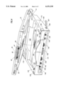
- FIG. 1 shows a port replicator docking unit, which has been constructed according to the principles of the present invention.
- the port replicator 100 comprises a computer docking bay 110, which is configured to receive a compatible portable computer on the port replicator 100.
- the right and left tabs 112, 114 are provided on a front wall 111 of the docking unit 100.
- the tabs 112, 114 project rearward from the front wall 111 and are located over wells 116, 118.
- tabs 112, 114 mate with rectangular recesses 12 on the front of a compatible portable computer 10, allowing the front of the portable computer to be physically connected into the docking unit.
- the portable computer 10 is aligned in the computer docking bay area 110 so that the rectangular recesses 12 in the portable computer's housing are aligned in front of each of the projecting tabs 112, 114.
- the computer is then moved in the direction of arrow 14 so that the tabs 112, 114 engage the recesses 12. This connection has the effect of hinging the front of the computer 10 to the port replicator 100.
- a cutout 120 is formed in the central section of the docking unit 100. In the preferred embodiment, this extends entirely through the docking unit. This has the advantage of providing an easy means for carrying the docking unit, forming an improvised handle. Rearward of the cutout 120 is battery charging cradle 122.
- the cradle 122 is sized and adapted to receive battery 124.
- the battery's electrodes 126 electrically mate with the charging connector 127 in the charging cradle 122.
- FIG. 3 shows the battery 124 installed in the charging cradle.
- the top wall 125 of the battery 124 is flush or level with a bay wall 129 of the docking unit 100.
- a battery charging unit 128 is located in an electronics section 127 under bay wall 129 of the docking unit 100.
- the battery is a lithium ion battery and the charger 128 is adapted to provide the charging profile required for lithium ion batteries.
- a combination connector 130 Behind the battery charging cradle 122 on the top bay wall 129 of the docking unit 100 is a combination connector 130.
- the docking unit's combination connector 130 electrically mates with the compatible connector 130a on the bottom of the portable computer 10. This allows the portable computer's communication ports to be replicated at the communication port connectors 131 on the port replicator 100. Also, the combination connector 130 provides electrical power to the portable computer 10.
- the rear of the docking unit 100 has the array of communication port connectors or jacks 131.
- these connectors comprise an RJ-45 connector 142 for connection to a network, a USB connector 144, a power supply connector 146, a parallel printer port connector 148, a serial port connector 150, a VGA video port connector 149, mouse port connector 152, and a keyboard port connector 154.
- These replicated port connectors 140 function as the replicated port connectors of the portable computer installed in the docking bay area. The ports of the portable computer connect to the replicated port connectors via the combination connector 130.
- the docking unit 100 comprises a rear wall 182 that projects upward, over the docking bay 110 at the rear side of the unit 100.
- This projecting wall 182 is preferably arcuate and projects in front of the communication port connectors 18 of the portable computer. This effectively prevents the simultaneous connection of devices to the portable computer's communication port connectors and the same connectors of the docking unit, preventing incompatible electrical connection.
- the set of communication port connectors 18 of the portable computer include a parallel printer port connector 45, a serial port connector 46, and a VGA video port connector 47. These connectors 18 are accessed during mobile operation by opening the door 20.
- the final docked state is shown in FIG. 5, when the computer 10 is installed on the docking unit 100, the projecting wall 182 holds the door 20 closed, preventing access to the portable computer's communication port connectors.
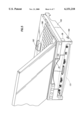
- the docking unit 100 has a wedge lateral cross-section. As shown, when the portable computer 10 is installed on the docking unit, the docking unit's wedge shape inclines the portable computer's keyboard 180 and pointing device 183 towards the user at an angle of between 7° and 13°, preferably 10°. This provides a more comfortable typing angle for the user, allowing the use of the portable computer's keyboard when the portable computer is connected into the docking unit 100 without necessitating an extra, desktop-version keyboard.
- docking unit 100 and portable computer 10 have a system for securing the computer to the unit.
- the docking unit has two latching elements 132, 134 in the docking bay 110. They allow the portable computer 10 to be latched on docking unit.
- lowering the portable computer 10 onto the docking bay causes the bottom wall of the portable computer, surrounding the right and left latching holes 22, 24 to engage latch release buttons 168, 170.
- This causes the latching elements 132, 134 shown in their retracted position in FIG. 4, to extend upward and toward the rear of the docking unit 100.
- the latching elements 132, 134 thus extend into the right and left latching holes 22, 24 of the portable computer 10 to securely hold the rear of the portable computer 10 against the docking unit 100 in the docking bay 110.
- This in combination with the engagement of the tabs 112, 114 at the front of the portable computer retain the portable computer 10 securely in the docking bay 110.
- the latching system forms part of a security system for the portable computer.
- the latching elements 132, 134 prevent the portable computer 10 from being removed from the docking unit 100, and the docking unit is, in turn, secured at a work area via a locking cable arrangement that engages locking port 184.
- a Kensington (trade name) cable system is used that engages the port 184 to lock and secure the docking unit 100 to a workstation via a cable 221 shown schematically.
- the right and left latching elements 132, 134 release the computer 10 and are returned to the retracted position by depressing right and left latch release buttons 136, 138, respectively.
- the latch release buttons 136, 138 in combination with an undock request button 186 prevent removal of the portable computer 10 when it is docked to the docking unit 100 by unauthorized persons.
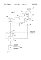
- FIG. 6 is a schematic plan view showing the latch control system that operates the latching elements, which is located in the electronic section 127 of the docking unit 100, according to the present invention.
- the right and left latch release buttons 136, 138 each comprise elongate, metal rods 302, 304, respectively. Additionally, the body portion of the buttons 136, 138 each have camming surfaces 306, 308. When each of the latch release buttons 136, 138 is depressed, the camming surfaces 306 and 308 engage arm portions 310, 312 of the latching elements 132, 134. This causes the latching elements 132, 134 to be retracted, and thereby release the computer 10 from the docking unit 100.
- each of the metal arms 302, 304 extends to a spring loaded locking element 314.
- spring 316 biases the locking element 314 in the direction of arrow 318 against wall 320.
- depression of of the latch release buttons 136, 138 causes the pointed, distal ends of the metal rods 304, 308 to engage the inclined surfaces 322, 324 of the locking element 314.
- the locking element 314 is free to rotate counter to arrow 318 to accommodate the movement of each of the rods in the direction of arrows 326.
- FIG. 7 shows a latch control system for operating the solenoid 332.
- a microcontroller 342 located in the portable computer system 10 monitors for depression of the undock request button 186, which is located on the docking unit's right sidewall, see FIG. 1.
- the microcontroller 342 communicates to the computer system's operating system to request the entrance of a password by the user. If the proper password is entered, the operating system 342 communicates this to the microcontroller 340, which signals, via an I 2 C bus, a latch 344 in the dock.
- the latch generates a pulse to a release BJT transistor 346, which activates on retracting MOSFET 348.
- Capacitor 350 controls the period of time the MOSFET is turned on. This operates the solenoid 332 to retract the arm 330. Successful retraction of the arm 330 is detected by switch 336.
- the latch 344 fails to detect the change in state of the arm 330 of the solenoid 332 via switch 336, the latch again issues a pulse to BJT 346 to try to attempt to retract the arm again. This continues until the arm 330 is successfully retracted.
- the microcontroller 340 functions as a docking detection system to detect the coupling of the computer's connector 130a to the combination detector 130 on the dock 100. When this event is detected, and an automatic locking state has been selected by the user in the operating system 342, the microcontroller 340 issues a signal to latch 344 to enter a locked state.
- the latch generates a pulse via a locking BJT transistor 354 which operates MOSFET 356 to extend the arm 330 of the solenoid 332.
- Capacitor 351 maintains the on state of MOSFET 356 for the time required for the solenoid to change states.
- the successful movement of the solenoid arm 330 is detected by the feedback from the switch 336 to latch 344.
- the latch continues to attempt to extend the arm 330 until it is successful.
- Extension of the solenoid arm prevents the rotation of the locking element 314 shown in FIG. 6. This prevents the depression of buttons 136, 138 and thus the undocking of the portable computer 10 from the docking unit 100.
- the portable computer comprises a middle docking unit such that the portable computer unit is latched to the middle docking unit and the middle docking unit is latched to the port replicator.
- middle docking units provide extended multimedia capabilities to the portable computer. This system allows all three sections to be secured to the work area with a single locking cable.
Abstract
Description
Claims (12)
Priority Applications (1)
| Application Number | Priority Date | Filing Date | Title |
|---|---|---|---|
| US09/137,592 US6151218A (en) | 1998-08-21 | 1998-08-21 | Physical security system for portable computer/port replicator |
Applications Claiming Priority (1)
| Application Number | Priority Date | Filing Date | Title |
|---|---|---|---|
| US09/137,592 US6151218A (en) | 1998-08-21 | 1998-08-21 | Physical security system for portable computer/port replicator |
Publications (1)
| Publication Number | Publication Date |
|---|---|
| US6151218A true US6151218A (en) | 2000-11-21 |
Family
ID=22478160
Family Applications (1)
| Application Number | Title | Priority Date | Filing Date |
|---|---|---|---|
| US09/137,592 Expired - Lifetime US6151218A (en) | 1998-08-21 | 1998-08-21 | Physical security system for portable computer/port replicator |
Country Status (1)
| Country | Link |
|---|---|
| US (1) | US6151218A (en) |
Cited By (43)
| Publication number | Priority date | Publication date | Assignee | Title |
|---|---|---|---|---|
| US6424524B2 (en) * | 1998-08-21 | 2002-07-23 | Compaq Information Technologies Group, L.P. | Wedge-shaped port replicator for portable computer |
| US20020104005A1 (en) * | 2001-01-31 | 2002-08-01 | Yin Memphis Zhihong | Direction-sensitive, touch-activated security device and method of use therefor |
| US6501646B2 (en) * | 1998-10-21 | 2002-12-31 | Nec Corporation | Docking apparatus for note-type personal computer having improved releasing function |
| US6527591B1 (en) * | 2001-10-23 | 2003-03-04 | Hewlett-Packard Company | Expandable port replicator for computer underside docking |
| US6574102B2 (en) * | 2000-04-17 | 2003-06-03 | International Business Machines Corporation | Docking station for portable computer and docking structure thereof |
| US6606243B2 (en) * | 1997-04-23 | 2003-08-12 | Hitachi, Ltd. | Information processing unit and information processing related units |
| US20030155395A1 (en) * | 2002-01-08 | 2003-08-21 | Metso Automation Oy | Method and equipment in connection with a paper machine or a paper web finishing apparatus |
| US20030161099A1 (en) * | 2002-02-04 | 2003-08-28 | Yoshihiko Aoki | Information display apparatus |
| US20040052036A1 (en) * | 2002-09-16 | 2004-03-18 | Deluga Ronald E. | Multistage undocking assembly and system and method incorporating same |
| US6742070B2 (en) * | 1998-09-14 | 2004-05-25 | Fujitsu Limited | Function-expansion device detachably connecting electronic equipment |
| US20040145871A1 (en) * | 2003-01-24 | 2004-07-29 | Samsung Electronics Co., Ltd. | Locking apparatus and method between portable terminal and cradle for terminal |
| US6778385B2 (en) * | 1999-04-19 | 2004-08-17 | Hewlett-Packard Development Company, L.P. | Portable computer with removable bottom component housing |
| EP1653327A2 (en) * | 2004-10-28 | 2006-05-03 | Hewlett-Packard Development Company, L.P. | Docking station |
| US20060107073A1 (en) * | 2004-11-12 | 2006-05-18 | International Business Machines Corporation | System and method for equipment security cable lock interface |
| US7298611B1 (en) | 2006-06-30 | 2007-11-20 | Carnevali Jeffrey D | Portable device docking station |
| US20080020614A1 (en) * | 2006-07-20 | 2008-01-24 | Samsung Electronics Co., Ltd. | Portable terminal with locking release device |
| US20080174270A1 (en) * | 2007-01-22 | 2008-07-24 | Guillermo Castano De La Serna | Integrated battery and charger for laptop computer |
| US20080198505A1 (en) * | 2007-02-16 | 2008-08-21 | Inventec Corporation | Height adjustment mechanism |
| US20080229434A1 (en) * | 2005-06-28 | 2008-09-18 | International Business Machines Corporation | Security Locking Apparatus and Method for Portable Computer |
| KR100907989B1 (en) * | 2002-08-29 | 2009-07-16 | 엘지전자 주식회사 | Docking station of portable hybrid computer |
| US20090198853A1 (en) * | 2008-02-01 | 2009-08-06 | Eduardo Escamilla | System and method for releasing a peripheral slice from an information handling system |
| US20090260081A1 (en) * | 2008-04-14 | 2009-10-15 | Tecsys Development, Inc. | System and Method for Monitoring and Securing a Baseboard Management Controller |
| US20120094528A1 (en) * | 2009-09-17 | 2012-04-19 | Matthew Leigh Vroom | Docking Station for an Electronic Device with Improved Electrical Interface |
| US8179672B2 (en) | 2006-06-30 | 2012-05-15 | National Products, Inc. | Portable device docking station |
| US20120170203A1 (en) * | 2011-01-03 | 2012-07-05 | Ems Technologies, Inc. | Quick Mount System for Computer Terminal |
| US8427826B2 (en) | 2010-11-29 | 2013-04-23 | L&P Property Management Company | Computer docking station assembly |
| US20130301201A1 (en) * | 2012-05-10 | 2013-11-14 | Compal Electronics, Inc. | Portable electronic device and cradle |
| US20140285963A1 (en) * | 2011-10-02 | 2014-09-25 | Intal Tech Ltd. | Portable computer vehicle dock |
| US20150186630A1 (en) * | 2013-12-31 | 2015-07-02 | Henge Docks Llc | Motorized Horizontal Docking Station Having Integrated Locking Mechanism |
| US9285831B2 (en) | 2009-09-17 | 2016-03-15 | Henge Docks Llc | Docking station for portable electronics |
| US9370114B1 (en) * | 2009-01-16 | 2016-06-14 | Amazon Technologies, Inc. | Accessory attachment mechanism |
| US9575510B1 (en) | 2015-10-23 | 2017-02-21 | Matthew Leigh Vroom | Precision docking station for an electronic device having integrated retention mechanism |
| US20170068272A1 (en) * | 2015-09-04 | 2017-03-09 | Erik Jens Loscalzo | Laptop computer case with integrated file storage and batteries |
| US9727084B2 (en) | 2015-10-23 | 2017-08-08 | Henge Docks Llc | Drivetrain for a motorized docking station |
| US9811118B2 (en) | 2015-10-23 | 2017-11-07 | Henge Docks Llc | Secure assembly for a docking station |
| US9882310B2 (en) * | 2016-02-18 | 2018-01-30 | Omron Corporation | Connection structure and apparatus unit |
| US9927838B2 (en) | 2013-12-31 | 2018-03-27 | Henge Docks Llc | Sensor system for docking station |
| US10101770B2 (en) * | 2016-07-29 | 2018-10-16 | Mobile Tech, Inc. | Docking system for portable computing device in an enclosure |
| US10365688B1 (en) | 2018-04-19 | 2019-07-30 | Henge Docks Llc | Alignment sleeve for docking station |
| US10461451B1 (en) * | 2018-06-12 | 2019-10-29 | Aplex Technology Inc. | Electronic device quick release structure |
| US10599182B1 (en) * | 2018-07-27 | 2020-03-24 | The United States Of America As Represented By The Secretary Of The Navy | Docking station apparatus |
| US10782735B2 (en) | 2012-12-05 | 2020-09-22 | Mobile Tech, Inc. | Docking station for tablet device |
| US10977572B2 (en) * | 2013-03-15 | 2021-04-13 | Exterro, Inc. | Intelligent searching of electronically stored information |
Citations (21)
| Publication number | Priority date | Publication date | Assignee | Title |
|---|---|---|---|---|
| US4558914A (en) * | 1982-09-23 | 1985-12-17 | Gould Inc. | Readily expandable input/output construction for programmable controller |
| US5175671A (en) * | 1990-03-20 | 1992-12-29 | Kabushiki Kaisha Toshiba | Expanding apparatus for portable electronic apparatus |
| US5450271A (en) * | 1992-10-29 | 1995-09-12 | International Business Machines Corporation | Portable computer docking apparatus including a key mechanism controlling a power supply and a locking mechanism |
| US5461546A (en) * | 1989-12-15 | 1995-10-24 | Kabushiki Kaisha Toshiba | Connecting apparatus for connecting portable computers |
| US5488572A (en) * | 1994-05-04 | 1996-01-30 | Compaq Computer Corp. | Portable computer system for docking to an expansion base unit |
| US5504649A (en) * | 1991-09-06 | 1996-04-02 | Kabushiki Kaisha Toshiba | Electronic apparatus system including expansion unit which has an expansion device for expanding the function of an electronic apparatus and which is connectable to the electronic apparatus by means of a card connector |
| US5535093A (en) * | 1994-06-20 | 1996-07-09 | International Business Machines Corporation | Portable computer docking device having a first rotatable connector and a second connector |
| US5627974A (en) * | 1993-11-12 | 1997-05-06 | Texas Instruments Incorporated | Computer docking system with means for allowing a microprocessor in a docking station to talk to a central processing unit in a docked portable computer |
| US5648762A (en) * | 1994-02-04 | 1997-07-15 | Canon Kabushiki Kaisha | Built-in electronic apparatus and device-detaching method therefor |
| US5664118A (en) * | 1994-03-28 | 1997-09-02 | Kabushiki Kaisha Toshiba | Computer system having detachable expansion unit |
| US5768101A (en) * | 1996-12-20 | 1998-06-16 | Compaq Computer Corporation | Portable computer docking base with ducted interior cooling air passsage |
| US5812356A (en) * | 1996-08-14 | 1998-09-22 | Dell U.S.A., L.P. | Computer docking system having an electromagnetic lock |
| US5822185A (en) * | 1996-12-06 | 1998-10-13 | Dell U.S.A., L.P. | Ergonomic docking station for a portable computer |
| US5838548A (en) * | 1995-10-26 | 1998-11-17 | The Whitaker Corporation | Network apparatus |
| US5847924A (en) * | 1995-12-08 | 1998-12-08 | Samsung Electronics Co., Ltd. | Notebook computer assembly having an attachable compact extension module for connecting peripheral equipment to a notebook computer |
| US5859762A (en) * | 1996-05-13 | 1999-01-12 | International Business Machines Corporation | Docking station for portable computers |
| US5862036A (en) * | 1997-04-08 | 1999-01-19 | Inventec Corporation | Dock for connecting a notebook computer to a PC |
| US5864294A (en) * | 1996-04-01 | 1999-01-26 | Acer, Inc. | Method and device for expanding computer function |
| US5870283A (en) * | 1996-03-28 | 1999-02-09 | International Business Machines Corporation | Portable computer docking unit having an inhibitor for inhibiting movement of a mechanical lock to a lock position |
| US5911042A (en) * | 1996-03-02 | 1999-06-08 | Kabushiki Kaisha Toshiba | Computer system having expansion unit |
| US5911777A (en) * | 1996-07-05 | 1999-06-15 | Ncr Corporation | Method and apparatus for reporting unauthorized attempt to release a portable computer from a docking station |
-
1998
- 1998-08-21 US US09/137,592 patent/US6151218A/en not_active Expired - Lifetime
Patent Citations (21)
| Publication number | Priority date | Publication date | Assignee | Title |
|---|---|---|---|---|
| US4558914A (en) * | 1982-09-23 | 1985-12-17 | Gould Inc. | Readily expandable input/output construction for programmable controller |
| US5461546A (en) * | 1989-12-15 | 1995-10-24 | Kabushiki Kaisha Toshiba | Connecting apparatus for connecting portable computers |
| US5175671A (en) * | 1990-03-20 | 1992-12-29 | Kabushiki Kaisha Toshiba | Expanding apparatus for portable electronic apparatus |
| US5504649A (en) * | 1991-09-06 | 1996-04-02 | Kabushiki Kaisha Toshiba | Electronic apparatus system including expansion unit which has an expansion device for expanding the function of an electronic apparatus and which is connectable to the electronic apparatus by means of a card connector |
| US5450271A (en) * | 1992-10-29 | 1995-09-12 | International Business Machines Corporation | Portable computer docking apparatus including a key mechanism controlling a power supply and a locking mechanism |
| US5627974A (en) * | 1993-11-12 | 1997-05-06 | Texas Instruments Incorporated | Computer docking system with means for allowing a microprocessor in a docking station to talk to a central processing unit in a docked portable computer |
| US5648762A (en) * | 1994-02-04 | 1997-07-15 | Canon Kabushiki Kaisha | Built-in electronic apparatus and device-detaching method therefor |
| US5664118A (en) * | 1994-03-28 | 1997-09-02 | Kabushiki Kaisha Toshiba | Computer system having detachable expansion unit |
| US5488572A (en) * | 1994-05-04 | 1996-01-30 | Compaq Computer Corp. | Portable computer system for docking to an expansion base unit |
| US5535093A (en) * | 1994-06-20 | 1996-07-09 | International Business Machines Corporation | Portable computer docking device having a first rotatable connector and a second connector |
| US5838548A (en) * | 1995-10-26 | 1998-11-17 | The Whitaker Corporation | Network apparatus |
| US5847924A (en) * | 1995-12-08 | 1998-12-08 | Samsung Electronics Co., Ltd. | Notebook computer assembly having an attachable compact extension module for connecting peripheral equipment to a notebook computer |
| US5911042A (en) * | 1996-03-02 | 1999-06-08 | Kabushiki Kaisha Toshiba | Computer system having expansion unit |
| US5870283A (en) * | 1996-03-28 | 1999-02-09 | International Business Machines Corporation | Portable computer docking unit having an inhibitor for inhibiting movement of a mechanical lock to a lock position |
| US5864294A (en) * | 1996-04-01 | 1999-01-26 | Acer, Inc. | Method and device for expanding computer function |
| US5859762A (en) * | 1996-05-13 | 1999-01-12 | International Business Machines Corporation | Docking station for portable computers |
| US5911777A (en) * | 1996-07-05 | 1999-06-15 | Ncr Corporation | Method and apparatus for reporting unauthorized attempt to release a portable computer from a docking station |
| US5812356A (en) * | 1996-08-14 | 1998-09-22 | Dell U.S.A., L.P. | Computer docking system having an electromagnetic lock |
| US5822185A (en) * | 1996-12-06 | 1998-10-13 | Dell U.S.A., L.P. | Ergonomic docking station for a portable computer |
| US5768101A (en) * | 1996-12-20 | 1998-06-16 | Compaq Computer Corporation | Portable computer docking base with ducted interior cooling air passsage |
| US5862036A (en) * | 1997-04-08 | 1999-01-19 | Inventec Corporation | Dock for connecting a notebook computer to a PC |
Cited By (84)
| Publication number | Priority date | Publication date | Assignee | Title |
|---|---|---|---|---|
| US6606243B2 (en) * | 1997-04-23 | 2003-08-12 | Hitachi, Ltd. | Information processing unit and information processing related units |
| US6424524B2 (en) * | 1998-08-21 | 2002-07-23 | Compaq Information Technologies Group, L.P. | Wedge-shaped port replicator for portable computer |
| US6724623B2 (en) | 1998-08-21 | 2004-04-20 | Hewlett-Packard Development Company, L.P. | Wedge-shaped port replicator for portable computer |
| US6742070B2 (en) * | 1998-09-14 | 2004-05-25 | Fujitsu Limited | Function-expansion device detachably connecting electronic equipment |
| US6501646B2 (en) * | 1998-10-21 | 2002-12-31 | Nec Corporation | Docking apparatus for note-type personal computer having improved releasing function |
| US6778385B2 (en) * | 1999-04-19 | 2004-08-17 | Hewlett-Packard Development Company, L.P. | Portable computer with removable bottom component housing |
| US6574102B2 (en) * | 2000-04-17 | 2003-06-03 | International Business Machines Corporation | Docking station for portable computer and docking structure thereof |
| US20020104005A1 (en) * | 2001-01-31 | 2002-08-01 | Yin Memphis Zhihong | Direction-sensitive, touch-activated security device and method of use therefor |
| US6527591B1 (en) * | 2001-10-23 | 2003-03-04 | Hewlett-Packard Company | Expandable port replicator for computer underside docking |
| US6786773B2 (en) | 2001-10-23 | 2004-09-07 | Hewlett-Packard Development Company, L.P. | Expandable port replicator for computer underside docking |
| US20030155395A1 (en) * | 2002-01-08 | 2003-08-21 | Metso Automation Oy | Method and equipment in connection with a paper machine or a paper web finishing apparatus |
| US7042718B2 (en) * | 2002-02-04 | 2006-05-09 | Sony Corporation | Information display apparatus |
| US20030161099A1 (en) * | 2002-02-04 | 2003-08-28 | Yoshihiko Aoki | Information display apparatus |
| KR100907989B1 (en) * | 2002-08-29 | 2009-07-16 | 엘지전자 주식회사 | Docking station of portable hybrid computer |
| US6813145B2 (en) * | 2002-09-16 | 2004-11-02 | Hewlett-Packard Development Company, L.P. | Multistage undocking assembly and system and method incorporating same |
| US20040052036A1 (en) * | 2002-09-16 | 2004-03-18 | Deluga Ronald E. | Multistage undocking assembly and system and method incorporating same |
| US20040145871A1 (en) * | 2003-01-24 | 2004-07-29 | Samsung Electronics Co., Ltd. | Locking apparatus and method between portable terminal and cradle for terminal |
| US7130188B2 (en) * | 2003-01-24 | 2006-10-31 | Samsung Electronics Co., Ltd. | Locking apparatus and method between portable terminal and cradle for terminal |
| EP1653327A2 (en) * | 2004-10-28 | 2006-05-03 | Hewlett-Packard Development Company, L.P. | Docking station |
| EP1653327A3 (en) * | 2004-10-28 | 2008-11-19 | Hewlett-Packard Development Company, L.P. | Docking station |
| US20060107073A1 (en) * | 2004-11-12 | 2006-05-18 | International Business Machines Corporation | System and method for equipment security cable lock interface |
| US20080229434A1 (en) * | 2005-06-28 | 2008-09-18 | International Business Machines Corporation | Security Locking Apparatus and Method for Portable Computer |
| US8282687B2 (en) * | 2005-06-28 | 2012-10-09 | International Business Machines Corporation | Security locking apparatus and method for portable computer |
| US20080002369A1 (en) * | 2006-06-30 | 2008-01-03 | Carnevali Jeffrey D | Portable device docking station |
| US7573706B2 (en) | 2006-06-30 | 2009-08-11 | Carnevali Jeffrey D | Portable device docking station |
| US7298611B1 (en) | 2006-06-30 | 2007-11-20 | Carnevali Jeffrey D | Portable device docking station |
| US7315453B1 (en) | 2006-06-30 | 2008-01-01 | Carnevali Jeffrey D | Portable device docking station |
| US9036343B2 (en) | 2006-06-30 | 2015-05-19 | National Products, Inc. | Portable device docking station |
| US7417855B2 (en) | 2006-06-30 | 2008-08-26 | Carnevali Jeffrey D | Portable device docking station |
| US20080002345A1 (en) * | 2006-06-30 | 2008-01-03 | Carnevali Jeffrey D | Portable device docking station |
| US8179672B2 (en) | 2006-06-30 | 2012-05-15 | National Products, Inc. | Portable device docking station |
| US7508661B2 (en) | 2006-06-30 | 2009-03-24 | Carnevali Jeffrey D | Portable device docking station |
| US20080002353A1 (en) * | 2006-06-30 | 2008-01-03 | Carnevali Jeffrey D | Portable device docking station |
| US20080002351A1 (en) * | 2006-06-30 | 2008-01-03 | Carnevali Jeffrey D | Portable device docking station |
| US7983629B2 (en) * | 2006-07-20 | 2011-07-19 | Samsung Electronics Co., Ltd | Portable terminal with locking release device |
| US20080020614A1 (en) * | 2006-07-20 | 2008-01-24 | Samsung Electronics Co., Ltd. | Portable terminal with locking release device |
| US20080174270A1 (en) * | 2007-01-22 | 2008-07-24 | Guillermo Castano De La Serna | Integrated battery and charger for laptop computer |
| US7817415B2 (en) * | 2007-02-16 | 2010-10-19 | Inventec Corporation | Height adjustment mechanism |
| US20080198505A1 (en) * | 2007-02-16 | 2008-08-21 | Inventec Corporation | Height adjustment mechanism |
| US20090198853A1 (en) * | 2008-02-01 | 2009-08-06 | Eduardo Escamilla | System and method for releasing a peripheral slice from an information handling system |
| US8634189B2 (en) * | 2008-02-01 | 2014-01-21 | Dell Products L.P. | System and method for releasing a peripheral slice from an information handling system |
| US20090260081A1 (en) * | 2008-04-14 | 2009-10-15 | Tecsys Development, Inc. | System and Method for Monitoring and Securing a Baseboard Management Controller |
| US8732829B2 (en) * | 2008-04-14 | 2014-05-20 | Tdi Technologies, Inc. | System and method for monitoring and securing a baseboard management controller |
| US9370114B1 (en) * | 2009-01-16 | 2016-06-14 | Amazon Technologies, Inc. | Accessory attachment mechanism |
| US20130137298A1 (en) * | 2009-09-17 | 2013-05-30 | Matthew Leigh Vroom | Docking Station for an Electronic Device with Improved Electrical Interface |
| US9285831B2 (en) | 2009-09-17 | 2016-03-15 | Henge Docks Llc | Docking station for portable electronics |
| US8512080B2 (en) * | 2009-09-17 | 2013-08-20 | Henge Docks Llc | Docking station for an electronic device with improved electrical interface |
| US20130303012A1 (en) * | 2009-09-17 | 2013-11-14 | Henge Docks Llc | Docking station for an electronic device with improved electrical interface |
| US8585443B1 (en) * | 2009-09-17 | 2013-11-19 | Henge Docks, LLC | Docking station for an electronic device with improved electrical interface |
| US8512079B2 (en) * | 2009-09-17 | 2013-08-20 | Henge Docks Llc | Docking station for an electronic device with improved electrical interface |
| US20140038450A1 (en) * | 2009-09-17 | 2014-02-06 | Henge Docks Llc | Docking Station for an Electronic Device with Improved Electrical Interface |
| US20120094528A1 (en) * | 2009-09-17 | 2012-04-19 | Matthew Leigh Vroom | Docking Station for an Electronic Device with Improved Electrical Interface |
| US8882545B2 (en) * | 2009-09-17 | 2014-11-11 | Henge Docks Llc | Docking station for an electronic device with improved electrical interface |
| US8427826B2 (en) | 2010-11-29 | 2013-04-23 | L&P Property Management Company | Computer docking station assembly |
| US8531829B2 (en) * | 2011-01-03 | 2013-09-10 | Ems Technologies, Inc. | Quick mount system for computer terminal |
| US20120170203A1 (en) * | 2011-01-03 | 2012-07-05 | Ems Technologies, Inc. | Quick Mount System for Computer Terminal |
| US20160209872A1 (en) * | 2011-10-02 | 2016-07-21 | Alexander Vasilevsky | Portable computer vehicle dock |
| US9557768B2 (en) * | 2011-10-02 | 2017-01-31 | Alexander Vasilevsky | Portable computer vehicle dock |
| US9298218B2 (en) * | 2011-10-02 | 2016-03-29 | Intal Tech Ltd. | Portable computer vehicle dock |
| US20140285963A1 (en) * | 2011-10-02 | 2014-09-25 | Intal Tech Ltd. | Portable computer vehicle dock |
| US9137913B2 (en) * | 2012-05-10 | 2015-09-15 | Compal Electronics, Inc. | Portable electronic device and cradle |
| US20130301201A1 (en) * | 2012-05-10 | 2013-11-14 | Compal Electronics, Inc. | Portable electronic device and cradle |
| US10782735B2 (en) | 2012-12-05 | 2020-09-22 | Mobile Tech, Inc. | Docking station for tablet device |
| US10977572B2 (en) * | 2013-03-15 | 2021-04-13 | Exterro, Inc. | Intelligent searching of electronically stored information |
| US9663977B2 (en) | 2013-12-31 | 2017-05-30 | Henge Docks Llc | Motorized horizontal docking station having integrated locking mechanism |
| US10459486B2 (en) | 2013-12-31 | 2019-10-29 | Brydge Technologies LLC | Motorized horizontal docking station having integrated locking mechanism |
| US9593510B2 (en) | 2013-12-31 | 2017-03-14 | Henge Docks Llc | Motorized horizontal docking station having integrated locking mechanism |
| US9650814B2 (en) | 2013-12-31 | 2017-05-16 | Henge Docks Llc | Alignment and drive system for motorized horizontal docking station |
| US9347245B2 (en) | 2013-12-31 | 2016-05-24 | Henge Docks Llc | Motorized horizontal docking station having integrated locking mechanism |
| US9725930B2 (en) * | 2013-12-31 | 2017-08-08 | Henge Docks Llc | Motorized horizontal docking station having integrated locking mechanism |
| US9927838B2 (en) | 2013-12-31 | 2018-03-27 | Henge Docks Llc | Sensor system for docking station |
| US20150186630A1 (en) * | 2013-12-31 | 2015-07-02 | Henge Docks Llc | Motorized Horizontal Docking Station Having Integrated Locking Mechanism |
| US9309698B2 (en) | 2013-12-31 | 2016-04-12 | Henge Docks Llc | Motorized horizontal docking station having integrated locking mechanism |
| US20170068272A1 (en) * | 2015-09-04 | 2017-03-09 | Erik Jens Loscalzo | Laptop computer case with integrated file storage and batteries |
| US9727084B2 (en) | 2015-10-23 | 2017-08-08 | Henge Docks Llc | Drivetrain for a motorized docking station |
| US9811118B2 (en) | 2015-10-23 | 2017-11-07 | Henge Docks Llc | Secure assembly for a docking station |
| US9575510B1 (en) | 2015-10-23 | 2017-02-21 | Matthew Leigh Vroom | Precision docking station for an electronic device having integrated retention mechanism |
| US9882310B2 (en) * | 2016-02-18 | 2018-01-30 | Omron Corporation | Connection structure and apparatus unit |
| US10754381B2 (en) | 2016-07-29 | 2020-08-25 | Mobile Tech, Inc. | Docking system for portable computing device |
| US10281955B2 (en) | 2016-07-29 | 2019-05-07 | Mobile Tech, Inc. | Docking system for portable computing device |
| US10101770B2 (en) * | 2016-07-29 | 2018-10-16 | Mobile Tech, Inc. | Docking system for portable computing device in an enclosure |
| US10365688B1 (en) | 2018-04-19 | 2019-07-30 | Henge Docks Llc | Alignment sleeve for docking station |
| US10461451B1 (en) * | 2018-06-12 | 2019-10-29 | Aplex Technology Inc. | Electronic device quick release structure |
| US10599182B1 (en) * | 2018-07-27 | 2020-03-24 | The United States Of America As Represented By The Secretary Of The Navy | Docking station apparatus |
Similar Documents
| Publication | Publication Date | Title |
|---|---|---|
| US6151218A (en) | Physical security system for portable computer/port replicator | |
| US6046571A (en) | Port replicator with secure integral battery charging cradle | |
| US6724623B2 (en) | Wedge-shaped port replicator for portable computer | |
| US6297963B1 (en) | Security docking cable for computer docking system | |
| US5450271A (en) | Portable computer docking apparatus including a key mechanism controlling a power supply and a locking mechanism | |
| US5995366A (en) | Computer anti-theft system and method | |
| US6331934B1 (en) | Computer docking station with anti-theft locking mechanisms for removable components | |
| EP0840197B1 (en) | Physical security system for portable computer | |
| US6522532B2 (en) | Cable docking system and method for a computer | |
| US6407914B1 (en) | Docking system for portable computer | |
| US5818691A (en) | Portable computer docking system with push to engage and push to disengage connection module | |
| US6135801A (en) | Computer underside docking method and apparatus | |
| US6549416B2 (en) | Portable computer docking station with protected connector | |
| US10019035B2 (en) | Tablet attachment system | |
| US6231371B1 (en) | Docking station for multiple devices | |
| CN103119349B (en) | In-wall dock for a tablet computer | |
| US5948074A (en) | Expansion unit having a security mechanism for inhibiting attachment and disconnection of the expansion unit to and from a portable computer | |
| US5313596A (en) | Motorized portable computer/expansion chassis docking system | |
| US5692400A (en) | Securing portable computers and associated docking systems | |
| US5579528A (en) | Computer system employing docking bay with spring loaded connector pins and file coherency method | |
| US6980422B2 (en) | Internal USB drive housing bay | |
| US6366458B1 (en) | Docking unit for portable electronic device and locking method of docking unit | |
| US7085132B2 (en) | Vertically docking an information handling system to a media slice | |
| US7079385B1 (en) | Docking station lock and its link assembly | |
| JPH0580886A (en) | Lock structure for personal computer system |
Legal Events
| Date | Code | Title | Description |
|---|---|---|---|
| AS | Assignment |
Owner name: DIGITAL EQUIPMENT CORPORATION, MASSACHUSETTS Free format text: ASSIGNMENT OF ASSIGNORS INTEREST;ASSIGNORS:PIRDY, SCOTT;BAUCOM, ALLAN SCOTT;HENNESSY, RICHARD;AND OTHERS;REEL/FRAME:009557/0235 Effective date: 19981021 |
|
| AS | Assignment |
Owner name: DIGITAL EQUIPMENT CORPORATION, MASSACHUSETTS Free format text: ASSIGNMENT OF ASSIGNORS INTEREST;ASSIGNORS:PIRDY, SCOTT;BAUCOM, ALLAN SCOTT;HENNESSEY, RICHARD;AND OTHERS;REEL/FRAME:009743/0131 Effective date: 19990118 |
|
| STCF | Information on status: patent grant |
Free format text: PATENTED CASE |
|
| FEPP | Fee payment procedure |
Free format text: PAYOR NUMBER ASSIGNED (ORIGINAL EVENT CODE: ASPN); ENTITY STATUS OF PATENT OWNER: LARGE ENTITY |
|
| AS | Assignment |
Owner name: COMPAQ INFORMATION TECHNOLOGIES GROUP, L.P., TEXAS Free format text: ASSIGNMENT OF ASSIGNORS INTEREST;ASSIGNORS:DIGITAL EQUIPMENT CORPORATION;COMPAQ COMPUTER CORPORATION;REEL/FRAME:012447/0903;SIGNING DATES FROM 19991209 TO 20010620 |
|
| AS | Assignment |
Owner name: HEWLETT-PACKARD DEVELOPMENT COMPANY, L.P., TEXAS Free format text: CHANGE OF NAME;ASSIGNOR:COMPAQ INFORMANTION TECHNOLOGIES GROUP LP;REEL/FRAME:014102/0224 Effective date: 20021001 |
|
| FPAY | Fee payment |
Year of fee payment: 4 |
|
| FPAY | Fee payment |
Year of fee payment: 8 |
|
| FPAY | Fee payment |
Year of fee payment: 12 |