US6151651A - Communication link with isochronous and asynchronous priority modes coupling bridge circuits in a computer system - Google Patents
Communication link with isochronous and asynchronous priority modes coupling bridge circuits in a computer system Download PDFInfo
- Publication number
- US6151651A US6151651A US09/098,360 US9836098A US6151651A US 6151651 A US6151651 A US 6151651A US 9836098 A US9836098 A US 9836098A US 6151651 A US6151651 A US 6151651A
- Authority
- US
- United States
- Prior art keywords
- bus
- isochronous
- integrated circuit
- asynchronous
- recited
- Prior art date
- Legal status (The legal status is an assumption and is not a legal conclusion. Google has not performed a legal analysis and makes no representation as to the accuracy of the status listed.)
- Expired - Lifetime
Links
Images


Classifications
-
- H—ELECTRICITY
- H04—ELECTRIC COMMUNICATION TECHNIQUE
- H04L—TRANSMISSION OF DIGITAL INFORMATION, e.g. TELEGRAPHIC COMMUNICATION
- H04L12/00—Data switching networks
- H04L12/28—Data switching networks characterised by path configuration, e.g. LAN [Local Area Networks] or WAN [Wide Area Networks]
- H04L12/40—Bus networks
- H04L12/40052—High-speed IEEE 1394 serial bus
- H04L12/40058—Isochronous transmission
-
- G—PHYSICS
- G06—COMPUTING; CALCULATING OR COUNTING
- G06F—ELECTRIC DIGITAL DATA PROCESSING
- G06F13/00—Interconnection of, or transfer of information or other signals between, memories, input/output devices or central processing units
- G06F13/38—Information transfer, e.g. on bus
- G06F13/40—Bus structure
- G06F13/4004—Coupling between buses
- G06F13/4027—Coupling between buses using bus bridges
- G06F13/405—Coupling between buses using bus bridges where the bridge performs a synchronising function
- G06F13/4054—Coupling between buses using bus bridges where the bridge performs a synchronising function where the function is bus cycle extension, e.g. to meet the timing requirements of the target bus
-
- H—ELECTRICITY
- H04—ELECTRIC COMMUNICATION TECHNIQUE
- H04L—TRANSMISSION OF DIGITAL INFORMATION, e.g. TELEGRAPHIC COMMUNICATION
- H04L12/00—Data switching networks
- H04L12/28—Data switching networks characterised by path configuration, e.g. LAN [Local Area Networks] or WAN [Wide Area Networks]
- H04L12/40—Bus networks
- H04L12/40052—High-speed IEEE 1394 serial bus
- H04L12/40123—Interconnection of computers and peripherals
Definitions
- the invention relates to computer systems and more particularly to a computer system including a bus having a relatively high bandwidth and a relatively low pin count.
- PCI Peripheral Component Interface
- the north bridge functions generally as a switch connecting CPU 107, a graphics bus 109 such as the Advanced Graphics Port (AGP) bus, and the PCI bus to main memory 111.
- the memory controller function is also located in the north bridge.
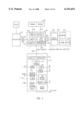
- the south bridge generally provides the interface to the input/output (I/O) portion of the system with the exception of video output as illustrated in the prior art computer architecture shown of FIG. 1.
- the south bridge 105 provides a bridge between the PCI bus and legacy PC-AT (Advanced Technology) logic.
- the south bridge also provides a bridge to the legacy ISA bus 115, the Integrated Device Electronics (IDE) disk interface 117 and the Universal Serial Bus (USB) 119.
- IDE Integrated Device Electronics
- USB Universal Serial Bus
- the PCI bus between the north bridge and the south bridge also functions as the interconnect bus for many add-in functions. That results in a significant number of pins on the north bridge circuit 103 and the south bridge circuit 105 to account for the add-in functions. That also results in a lack of determinism in the system because any function on the PCI bus can become master of the bus and tie up the bus.
- communication between the CPU and the resources in the south bridge, or between the resources in or coupled to the south bridge and system memory 111 should be deterministic in the sense of knowing what throughput is available for a particular transfer and the latency that is involved for that transfer.
- the invention provides a computer architecture that includes a new interconnect bus between the north bridge and the south bridge integrated circuits. As part of the new architecture, the PCI bus no longer connects to the north bridge integrated circuit.
- the invention provides a computer system that includes a first processor integrated circuit.
- a first bridge integrated circuit is coupled to the processor via a host bus.
- the computer system includes an interconnection bus that couples the first bridge circuit and a second bridge circuit.
- the interconnection bus provides a first transfer mode for asynchronous data and a second transfer mode for isochronous data.
- the interconnection bus provides for a maximum latency and guarantees a minimum throughput for isochronous and asynchronous data.
- a method of communicating information in a computer system includes a processor coupled to a first (north) bridge integrated circuit by a host bus and an interconnection bus connecting a second (south) bridge integrated circuit to the first (north) bridge integrated circuit.
- the interconnection bus provides a first transfer mode for asynchronous data and a second transfer mode for isochronous data on the interconnection bus. Data is transmitted between the first bridge integrated circuit and the second bridge integrated circuit in either the first or the second transfer modes via the interconnection bus.
- FIG. 1 depicts a prior art personal computer architecture.
- FIG. 2 depicts a first embodiment of the invention showing a point-to-point interconnect between the north bridge and the south bridge.
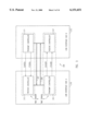
- FIG. 3 shows further details of the interconnect bus and the bus interfaces.
- FIG. 4 illustrates a flowchart for determining when to enter isochronous priority mode.
- FIG. 5 illustrates the link layer, protocol layer and physical layer of the bus.
- FIG. 6 illustrates one channel of the link layer.
- FIG. 7 illustrates the whole and half bus modes on the bus according to one embodiment of the invention.
- FIG. 8 is a flow diagram illustrating when a local controller should grant whole-bus mode to an external controller when the bus is in asynchronous priority mode.
- FIG. 9 is a flow diagram illustrating when a local controller should stay in whole-bus mode at the end of a bus cycle when the bus is in asynchronous priority mode.
- FIG. 10 is a flow diagram illustrating when a local controller stays in whole-bus mode after a whole-bus cycle is granted to the external side.
- FIG. 11 is a flow diagram illustrating when to grant whole bus mode while the bus is in isochronous priority mode.
- FIG. 12 shows a traffic example including isochronous and asynchronous data and whole and half-bus modes.
- FIG. 13 shows a flow chart for determining when to enter isochronous priority mode.
- FIG. 14 shows a computer system in which the graphics subsystem is coupled to the south bridge.
- FIG. 15 shows a computer system in which the processor and the north bridge have been integrated into a single integrated circuit which is coupled to the south bridge via the interconnection bus.
- FIG. 16 shows a computer system having an integrated processor and memory controller, which is coupled via the interconnection bus to the south bridge which has an integrated graphics controller function.
- FIG. 17 shows a computer system having an integrated processor and memory controller and graphics controller, which is coupled via the interconnection bus to the south bridge.
- a computer system includes north bridge integrated circuit 201 coupled between processor integrated circuit 203, system memory 207, graphics subsystem 214 and south bridge integrated circuit 211.
- the processor 203 may include both a processor core and other functions such as cache memory.
- the system (or main) memory shown in FIG. 2 utilizes Rambus dynamic random access memory (RDRAM) to provide fast DRAM access.
- the graphics subsystem is shown coupled to the north bridge integrated circuit via an accelerated graphics processor (AGP) bus.
- the graphics subsystem includes a graphics controller circuit 220, monitor 222 and frame buffer 224. Graphics controller circuits are known in the art. One example is the Intel 740 Graphics Accelerator integrated circuit. Other graphics buses beside the AGP may of course be utilized.
- the north bridge integrated circuit 201 provides a switching function connecting processor 203, graphics bus 205, memory 207, and interconnect bus 209.
- the interconnect bus replaces the PCI bus shown in the prior art computer architecture.
- the interconnect bus 209 has a high speed relative to the PCI bus and a relatively low pin count.
- the interconnect bus is also referred to herein as the high velocity--low pin count (HV-LPCP).
- System memory 207 and AGP bus 205 are coupled to the switch through memory controller 216 switch and AGP bridge circuit 218 respectively.
- Interconnect bus interface bus interface 210 (HV-LPC I/F) provides an interface to interconnect bus 209 for those circuits coupled to switch 212.
- the south bridge integrated circuit 211 provides a bridge between interconnect bus 209 and PCI bus 215 through PCI bridge 217.
- the south bridge 211 also provides a bridge to the 1394 bus through the 1394 interface circuit 219.
- Other functions that are also accessible through the PCI bus include IDE, Universal Serial Bus (USB), Industry Standard Architecture (ISA) bridge and Advanced Programmable Interrupt Controller (APIC).
- bus 209 provides a guaranteed minimum bandwidth and a maximum latency to data transferred over the bus. That is accomplished, as described further herein, by transferring data over the interconnect bus in frames, with each frame guaranteeing a portion of the frame for isochronous data and a portion of the frame for asynchronous data.
- Guaranteeing maximum latency for various channels connected to the bus is becoming more important as isochronous data streams are being conveyed between the south bridge and main memory.
- One source of such isochronous data is the IEEE 1394 bus.
- the PCI bus function has moved to the south bridge.
- the HV-LPC link 209 provides the PCI-resident functions all of the bandwidth that existed in the old architecture, and also provides additional capacity for new functions such as the 1394 bus.
- the 1394 bus can cause as big a load on the system as the PCI bus. That implies that the interconnect bus must be high speed relative to at least the PCI bus.
- a point-to-point bus can inherently run at higher speeds than a multi-drop bus such as the PCI bus since a point-to-point link has reduced electrical loading and reduced noise caused by reflections at tap points such as connectors. It is possible to provide a point to point link that operates at 25 times the speed of the PCI bus. Given this, the 32-bit wide PCI bus can be replaced by a 16-bit (or even an 8-bit link) while adding significant bandwidth.
- bus 209 which connects a first module (which may be a processor module on a north bridge as described further herein) and the interface module, includes bi-directional data portions 307 and 309.
- each data portion contains one byte (8 bits) of data.
- the number of bits on the data bus may be of size (2 n -1:0), where n is an integer>0 that meets the throughput requirements of the system.
- n is an integer>0 that meets the throughput requirements of the system.
- n is an integer>0 that meets the throughput requirements of the system.
- a minimum implementation may have one data bit in each direction.
- n equals 4, with each data portion having one byte.
- Bus 209 includes a unidirectional clock line CLKB2A and a unidirectional control line CTLB2A provided by bus interface 210 to bus interface 213.
- the "B2A” designation indicates that the signal is an output of side B and an input to side A.
- Bus 209 also includes a second unidirectional clock line CLKA2B and a second unidirectional control line CTLA2B, which are provided by side A to side B.
- the "A2B" designation indicates that the signal is an output of side A and an input to side B.
- the protocol uses clock-forwarding technology to reliably synchronize source data to a clock.
- CLKA2B and CLKB2A are preferably derived from the same source such that they are the same frequency and they do not drift.
- Each bus interface side includes a transmit controller and a receive controller. Data always flows from the transmit controller on one side to the receive controller on the other side.
- side A bus interface 210 in north bridge 201 includes transmit controller 315 and a receive controller 313.
- Side B bus interface 213 in south bridge 211 includes transmit controller 311 and receive controller 317.
- the two bi-directional portions 307 and 309 of the data bus are shown with arrows indicating their default direction of transfer.
- Data bus portion 307 transmits data in a default mode of operation, from transmit controller 311 to receive controller 313 (from side B to side A) synchronous with CLKB2A.
- Data portion 309 of the data bus is dedicated, in a default mode of operation to transmit data from transmit controller 315 to receive controller 317 (side A to side B), synchronously with CLKA2B.
- bus 209 is a point to point bus physically connecting precisely two integrated circuits. In that way, transfer speed across the bus may be maximized.
- some embodiments of the bus may connect more than two integrated circuits to the bus.
- the side A transmit controller delivers clock CLKA2B to the side B receive controller
- the side B transmit controller delivers clock CLKB2A to the side A receive controller.
- the side A transmit controller and side B receive controller are included in the same time domain, called time domain A
- the side B transmit controller and the side A receive controller are included in the same time domain, called time domain B.
- both side A and side B initialize to a mode of 16 bits wide and 800 megahertz data rate.
- the data rate is based on a clock (CLK) (meaning CLKA2B and CLKB2A) rate of 400 megahertz and the data is provided on each edge of the clock. So, if clock is 400 megahertz, this represents 800 million edges per second. Address phases and data phases of bus cycles transfer information at each edge of CLK. Thus, the edge rate of CLK specifies the maximum theoretical bandwidth of the bus rather than the cycle rate.
- bus cycles and messages Two kinds of traffic occur over bus 209: bus cycles and messages.
- the greatest amount of bandwidth is used by bus cycles, which are transfers of blocks of addressing information or addressing information and associated data sent from one link layer to the link layer on the other side.
- the addressing information determines where in the integrated circuit a particular access is targeted.
- a bus cycle may be a long or short bus cycle.
- a long bus cycle may utilize several hundred nanoseconds of bus time while a short bus cycle uses less than, e.g., 20 or 30 nanoseconds.
- the second type of bus traffic is messages, which are used to send protocol information across the link.
- messages are aligned to the rising edge of CLK and consume one CLK cycle and can occur at any time, including in the middle of bus cycles. In other embodiments, messages may last more than one cycle.
- the isochronous streams are guaranteed a specified amount of bandwidth during each frame on the bus.
- frames are 2 microseconds in length.
- FIG. 4 a flowchart illustrates one method of guaranteeing sufficient isochronous bandwidth according to the present invention.
- asynchronous transfers are granted priority over isochronous transfers (to minimize the latency of the asynchronous transfers), which is called asynchronous priority mode.
- the bus enters asynchronous priority mode at 403.
- asynchronous transfers will be transferred instead of isochronous transfers if there are asynchronous requesters for the bus.
- isochronous data may be transferred when the bus is in asynchronous priority mode when there is no asynchronous data to transfer. If the frame is not over at 405, step 407 determines whether it is necessary to start transferring only isochronous data (isochronous priority mode) to guarantee sufficient bandwidth is provided for isochronous data. If so, the bus switches to isochronous priority mode in step 409. The bus stays in isochronous priority mode until all isochronous transfers are complete. There is preferably some cushion factored into the isochronous determination in step 407 so that there is at least some time left in the particular frame after all isochronous data is transferred. After transferring all isochronous data, the bus returns to asynchronous priority mode at 413 until the frame is over at 415. It is possible for the bus to stay in asynchronous priority mode the entire frame without switching to isochronous priority mode as is described further herein.
- the bus 209 is very useful in situations-where high-bandwidth asynchronous traffic must be mixed with isochronous traffic.
- the bus protocol assumes (1) that system performance is adversely affected by the latency of asynchronous traffic, (2) asynchronous traffic can be delayed indefinitely without adversely affecting real-time data streams, (3) isochronous traffic must be guaranteed a specified amount of bandwidth and worst-case latency, and (4) as long as the bandwidth and latency requirements for isochronous traffic are met, then the latency between their requests and the transfer of the data has no adverse affect on system performance.
- the hardware on each side of the bus includes a physical layer, a protocol layer, and a link layer.
- the protocol layers for both sides of the bus include the same hardware elements. In this way, the bus is symmetrical with no centralized resources (as opposed to, for example, the PCI bus arbiter which in prior art systems was typically located in the north bridge of the PCI bus and arbitrates for all masters).
- the bus includes link layer 501, protocol layer 503, and physical layer 505.
- the physical layer will depend on such factors as the frequency of the bus, the number of devices on the bus, the length of the bus, as is known to those of skill in the art.
- the specification for the physical layer and the protocol layer is generally device independent, except for variations of the bus width and frequency.
- the specification for the link layer varies based on the requirements of the device.
- north bridge 201 may include three channels which are coupled to the bus interface 210 through switch 212.
- One channel is for processor 203, one for main memory 207, and one for the graphics subsystem 214.
- the corresponding south bridge 213 may include two channels: one for the 1394 interface and one for one for the PCI bus.
- additional channels may be provided for the USB because it has isochronous data, and/or for an IDE interface, and one for an expansion bus interface.
- the link layer also includes an arbiter 507 to determine the source of the next locally-generated bus cycle since there are typically multiple asynchronous and isochronous sources. The arbiters guarantee bandwidth to isochronous streams (within a maximum latency) while minimizing latency to asynchronous accesses.
- Each channel in the link layer includes FIFOs and queues of addressing information and data that have been sent across the bus or that will be sent across the bus.
- asynchronous transmit FIFO(s) 601 store asynchronous data that will be sent across the bus while asynchronous receive FIFO(s) 603 store asynchronous data received from the protocol layer.
- the channel shown in FIG. 6 also includes queues of asynchronous read requests 605 and access requests 607.
- Isochronous transmit and receive FIFO(s) 609 and 611 respectively store isochronous information for transmitting and store isochronous information that has been received.
- the link layer hardware unlike the protocol layer, is specific to the requirements of the local integrated circuit on which the link layer is implemented.
- FIFOs and queues are designed to the specific requirements of the channels being serviced by the link.
- the FIFOs of each channel are optional, based on the channel requirements. For example, one would not expect any isochronous transmit or receive FIFOs for the south bridge's PCI block, since the PCI protocol does not allow for guaranteed isochronous data transfers (although, nothing prevents a designer from including these for the PCI bus channel).
- the 1394 FIFO on the other hand would expect to have both isochronous transmit and receive FIFOs. It is also possible in certain situations that there may be only a single receive FIFO and potentially no transmit FIFOs at all.
- the FIFO may contain isochronous or asynchronous data; the FIFO may transmit data to the bus or receive data from the bus; the FIFO has a predetermined size (in bytes); the FIFO may be a master (controlled by local timing) or a slave (responding only to accesses); if a FIFO is a slave, then design considerations include what causes the slave FIFO to be loaded.
- the FIFO target address may be static or it may increment with each byte, in which case it will be reloaded periodically.
- the size of the isochronous FIFOs can be determined according to the following equation: (maximum required bandwidth in bytes per second) ⁇ (frame time in seconds) ⁇ 2. For example, to support a 600 megabyte per second data stream, the FIFO would be required to be 2400 bytes deep.
- the processor module's system memory channel has special requirements, since multiple streams from the interface module may attempt to access it. It requires several isochronous transmit and receive FIFOs and, potentially, multiple asynchronous FIFOs.
- the system memory channel may include a 2 ⁇ bandwidth RAM and an array of programmable head and tail pointers for various FIFOs.
- a typical implementation may include a 4K byte block of SRAM and 16 head and tail pointer pairs. Software configures these based on the channel requirements on the other side of the link.
- a bus cycle is defined as a block transfer of either addressing information by itself or addressing information followed by data.
- the address phase of a bus cycle transmits the addressing bytes over the link and the data phase, if there is one, transmits the associated data bytes over the link.
- the bus is write only in that reads are accomplished by (1) sending a read request from a first side to the second side, after which, (2) the read data is retrieved and, in a separate cycle, sent from the second side to the requesting side.
- Bus cycles are granted to either asynchronous or isochronous requesters. Requesters are link-layer devices that are currently requesting use of the link for a bus cycle.
- the address phase occurs at the beginning of each bus cycle and typically includes the type of bus cycle being transmitted, the number of bytes to be transmitted in the bus cycle, bus-specific cycle type and address and whether both halves of the bus are requested for the transfer. There are several types of cycles in one embodiment as illustrated in Table 1.
- the data bus of the illustrated embodiment is split in half, with the 8 least significant bits (LSBs) of each 16-bit block controlled by the side A time domain and the 8 most significant bits (MSBs) of each 16-bit block controlled by the side B time domain.
- the bus protocol allows one side to utilize both halves of the bus to transmit data.
- the "local half-bus” refers to the half of the bus that is defaulted to be owned by the local transmit controller on an integrated circuit (LSBs for side A and MSBs for side B).
- the "external half-bus” refers to the other half of the bus, the half that is defaulted to be owned by the transmit controller on the other side of the link.
- the protocol layer includes an arbiter (509 in FIG. 5), called the whole-bus mode arbiter, for the local half-bus to determine if it will be used to transmit data (default mode) or if it will be used to receive external data.
- Half-bus mode refers to the default state of the link, in which side A controls the LSBs and side B controls the MSBs in the illustrated embodiment.
- Whole-bus mode refers to the state in which both halves of the data bus have been granted to a transmit controller.
- the whole-bus mode arbiter only determines when to enter whole-bus mode. Arbitration for a locally-initiated bus cycle is handled via the link layer by the local request arbiter.
- Short bus cycles are completed solely on the local half-bus.
- Long accesses e.g., longer than 30 nanoseconds
- Short bus cycles are allowed to complete without being halted. Long bus cycles can be halted for higher-priority traffic and then re-started at a later time.
- FIG. 7 typical traffic over the bus 109 in whole and half-bus mode is illustrated.
- the side B half-bus, transferring data from side B to side A is shown at 702.
- the side A half-bus, transferring data from side A to side B is shown at 704.
- all short bus cycles e.g., accesses that consume 30 nanoseconds of bus time or less
- the short cycle shown at time period 701 which transfers data from side B to side A is completed solely on the local half-bus.
- time period 703 both halves of the bus are idle as indicated by the "I".
- side A begins a long access, which as described, may utilize several hundred nanoseconds of bus time.
- A transfers data only on the local half-bus.
- side B's whole-bus mode arbiter determines whether to grant its half-bus to the external controller during time period 707. Since side B is not using its local half-bus at this time, it grants its use to side A and the long cycle is completed in whole bus mode during time period 709. Thus, the bus is able to exploit idle time by granting use of an idle half-bus to a requesting half bus with a long transfer. Once the half-bus is granted by side B, the whole bus is utilized for the remainder of side A's bus cycle.
- side A executes another long cycle transferring data from side A to side B.
- a side B long cycle begins during time period 715.
- time period 717 side A's long cycle 713 has been completed and a short cycle from side A to side B occurs. Once that short cycle completes, side A is available to side B.
- the arbitration for side A's half-bus occurs during time period 719.
- Side A grants its half-bus to side B which causes the bus to switch to whole bus mode.
- the cycle completes in whole bus mode during time period 721. Once the bus cycle is complete, the bus again enters half-bus mode at 723.
- bus cycles may be interrupted and entering and leaving whole-bus mode differs according to whether the bus is operating in isochronous or asynchronous priority mode.
- Isochronous requesters should not send more bytes across the link, during a frame, than the programmed maximum bandwidth for that requester.
- Hardware may be implemented in the link layer to ensure that isochronous requesters comply with that requirement.
- bus traffic is grouped into 2-microsecond frames.
- Two counters associated with frames are used in the local request arbitration logic (507 in FIG. 5). They are the elapsed frame counter, which is used to specify how much bandwidth remains in the frame, and the isochronous byte counter, which is used to specify how much isochronous bandwidth remains to be transferred in the frame.
- NewFrame new frame
- the isochronous byte counter starts, at the beginning of each frame, at a value equal to the number of isochronous bytes that must be guaranteed to be transferred during the frame. It decrements with each isochronous byte transferred. It is programmed to be slightly higher than the actual maximum isochronous bandwidth of a frame. Shortly after the beginning of each frame, all the isochronous streams make their requests to send data across the bus during the next frame. The requests may be made in the illustrated embodiment within a predetermined time period after the frame starts.
- asynchronous transfers are granted priority over isochronous transfers (to minimize the latency of the asynchronous transfers), (asynchronous priority mode).
- counter(s) track of how much isochronous traffic passes during the frame and if the isochronous streams are in danger of running out of the required bandwidth for the frame, arbitration priority switches to the isochronous traffic, (isochronous-priority mode). In that way, a minimum amount of isochronous bandwidth can be guaranteed while minimizing latencies for asynchronous transfer requests.
- the priority switches back to the asynchronous traffic.
- the bus protocol includes two arbiters: the whole-bus mode arbiter 509 in the protocol layer and the local-request arbiter 507 in the link layer that determines which local requester will next be granted the local half-bus.
- the local request arbiter operates as follows.
- the link For each frame, the link either stays in asynchronous priority mode for the entire frame or (1) starts in asynchronous priority mode, (2) transitions to isochronous priority mode during the frame, and (3) then transitions again to asynchronous priority mode before the end of the frame as illustrated in FIG. 4.
- the rules for the local-request arbiter are very simple: asynchronous requesters are higher priority than isochronous requesters during asynchronous-priority mode and only isochronous requesters are granted bus cycles during isochronous-priority mode.
- the arbitration method for the group of asynchronous requesters is not limited other than it is required to be fair and to not cause deadlock situations.
- the arbitration scheme for the group of isochronous requesters may utilize a fixed priority scheme.
- the external transmit controller normally requests whole-bus mode during the address phase of the cycle. If whole-bus mode is not requested, then the local whole-bus mode arbiter will not grant whole-bus mode for the bus cycle. However, this rule changes during isochronous-priority mode (see below).
- the request for whole-bus mode can be an explicit bus message.
- the request is implicit.
- an implicit request can be, e.g., any transfer over a particular number of bytes, e.g., 32, which is automatically treated as a request for whole bus mode.
- the local arbiter determines if any other local requesters are present, and if not grants its local half-bus to the external transmit controller.
- FIG. 12 shows a traffic example including isochronous and asynchronous data and whole and half-bus mode.
- FIG. 12 illustrates how the arbiter optimizes for asynchronous transfers during periods of relatively loose traffic, but when asynchronous traffic dominates, the isochronous bandwidth is still guaranteed.
- isochronous bus cycles are assumed to consume slightly more than 50% of the available bandwidth.
- the bus goes into isochronous whole-bus mode. After isochronous whole bus mode is over, the bus is either idle or transferring asynchronous traffic for the remainder of the frame.
- the bus is in whole-bus mode again except this time, transferring asynchronous data.
- whole-bus mode may extend across frame boundaries as shown. All the isochronous requesters in frame 1201 complete their bus cycles before getting too close to the end of the frame and thus, isochronous priority mode is unnecessary.
- the bus enters isochronous-priority mode and the long asynchronous cycle 1209 shown in whole-bus mode is halted. After all the isochronous requesters on one side of the link have completed their bus cycles at 1211, the bus enters into whole-bus mode for the remainder of isochronous-priority mode. Then, after the other side completes all of its remaining isochronous bus cycles in whole-bus mode, the bus is placed back into asynchronous-priority mode. After that, the asynchronous traffic is allowed to continue, through to the next frame.
- a flowchart illustrates utilization of the frame counter and isochronous byte counter to enter and exit isochronous mode.
- the frame counter is loaded with the number of bytes per frame and the isochronous counter is loaded at 1301 with the maximum number of isochronous bytes that can be transferred each frame.
- the frame enters asynchronous priority mode.
- the frame counter is decremented at the data rate for each possible transfer across the bus (whether or not the bus is actually idle).
- the elapsed-frame counter has passed the isochronous-byte counter.
- the local hardware will enter isochronous-priority mode. Any side with an isochronous requester or a current isochronous bus cycle will then send an isochronous priority mode (IsoPriMode) message to the other side, so both sides will be in isochronous-priority mode. If there is a bulk asynchronous transfer taking place, it will be halted as illustrated in FIG. 12.
- IsoPriMode isochronous priority mode
- the first side that finishes all its isochronous bus cycles sends the asynchronous priority request (AsyPriReq) message across the bus to indicate that it is ready to enter asynchronous-priority mode. This automatically grants whole-bus mode to the other side.
- the second side continues isochronous bus cycles in whole-bus mode until they are complete. At this point the second side sends the asynchronous priority grant (AsyPriGnt) message, which places the link into asynchronous-priority mode.
- each link interface side could load the isochronous byte counter at the start of each frame with the actual isochronous byte count requested for the frame. That counter is then decremented for each isochronous byte transmitted.
- the bus switches to the isochronous priority mode to ensure the transfer of the isochronous bytes.
- the counters described as counting down may of course be implemented to count in other ways to determine the count value, e.g., the counters may also be implemented as up counters.
- the bus may switch to isochronous priority mode at a predetermined time in the frame and any remaining isochronous transfers are transferred at this time. That approach may increase the latency of asynchronous data somewhat, since there may be no need to switch to isochronous priority mode.
- Bus messages are transmitted over the least-significant byte of the data bus (which may vary, based on whether the bus is in whole-bus mode or half-bus mode when the byte is transmitted) while the control signal (CTLA2B, CTLB2A) is asserted.
- the control signals are used to send messages.
- assertion of the local control signal indicates that the least-significant byte of the data bus is transmitting a link message. This may happen when the bus is idle or at any time during a bus cycle.
- the least-significant byte of the bus may vary based on whether the bus is in whole-bus mode or half-bus mode.
- the local side can assert the control signal (CTLA2B OR CTLB2A) to generate the request for half bus mode (HalfBusReq) message without the benefit of the data bus.
- This message informs the external side that it must relinquish whole-bus mode, even though it may be in the middle of a bulk transfer.
- the external side is required to accommodate this request by generating a half bus grant (HalfBusGnt) message, after which the external bus cycle will continue over the external half-bus.
- a bus message can be transmitted during any CLK cycle, including when the bus is idle, during the address phase of a transfer, or during the data phase. After the message is transmitted, if there is a bus cycle taking place (and it is not requested to be stopped by the bus message), then the bus cycle will continue on the following CLK cycle, as if it were in suspended animation for a single CLK cycle.
- Bus messages use all the bytes that are owned by the transmitting side of the link at the time that the message is transmitted. So if the bus is in half-bus mode, the message will be placed on the least-significant byte of the local half-bus; if it is whole-bus mode then it will be placed on the least-significant byte of the whole bus.
- bus messages may be used for legacy signal transfers.
- Legacy signals are those signals in personal computer (or other) systems that are necessitated by the desire to ensure compatibility with older designs.
- the interface module may need to transmit legacy signal information to the processor module.
- bits(3:0) of the message are used to transmit the legacy signals STPCLK#, IGNNE#, CPURST, A20M#.
- Those legacy signals are known in the art and are not discussed further herein.
- the interface module (IM) transmits this data each time one of those signals change state.
- bus messages may be used to transfer interrupt signals states from the interface module to the processor module.
- bus message bits(3:0) are used to transfer interrupts SMI, NMI, INTR, INIT.
- the interface module transmits this data each time one of these signals change state.
- legacy information may be needed to be transferred from the processor module to the interface module.
- FERR# may be transferred in a specific bit position of a bus message.
- the processor module transmits this data each time one of the signals changes state.
- transferring of legacy information conflicts unduly with whole-bus mode and/or isochronous-priority mode operations
- separate signals may be utilized in the computer system for transferring some or all of the legacy and interrupt signals between the processor module and the interface module.
- Bus cycles are not halted during their address phase, only during their data phase.
- the requester of a halted bus cycle continues to request the cycle. Once it is granted again, data continues from the point where it left off.
- FIG. 14 Another architectural variant of FIG. 2 is shown in FIG. 14.
- graphics subsystem 214 has been moved from north bridge 210 to south bridge 211. That significantly reduces the pin count of the north bridge integrated circuit. Reduced pin count generally results in lower cost. That also allows data to be routed to the graphics subsystem 214 directly from 1394 host controller 219. Thus, e.g., data from a video camera (not shown) could be routed directly through the HVLPC interface controller 213 through AGP bridge 1405 to graphics subsystem 214.
- the graphics controller 1401 of graphics subsystem 214 may be located in south bridge 211.
- the graphics bus and/or the graphics controller integrated into south bridge 211 certain graphical functions may remain in the north bridge 201.
- the graphics port being used is the accelerated graphics port (AGP)
- the AGP lets the video processor in video/graphics controller 1401 access system memory 207 for graphics calculations.
- Graphics controllers typically access contiguous data structures in their local memory (frame buffer 1403) but if the data structures are stored in system memory, the structures can be dynamically allocated. Therefore the graphics controller needs to remap local memory addresses to system memory.
- the Graphics Address Remapping Table (GART) remaps addresses from the local memory for the graphics controller to the system memory. It is more convenient if that function is maintained close to the memory and therefore still resides in north bridge 201 in the embodiment described in FIG. 14.
- FIG. 15 another implementation exploiting the interconnection bus is shown in which the north bridge and the CPU are integrated together into a single integrated circuit 1501. That integration significantly reduces the pin count of the processor integrated circuit that incorporates the CPU. The reduction in pin count results from the removal of the bus interface, e.g. the Socket 7 bus which is shown in FIG. 14 as the host bus.
- a three port switch 1503 in CPU integrated circuit 1501 connects the memory controller 1505, CPU 1507, and the HV-LPC bus interface controller 1509. Note that the memory controller may include a Rambus controller to interface to system memory using RDRAM.
- the total pin count of the system is reduced which results in a reduction in cost.
- one architecture in use today uses a 321-pin CPU and a 328-pin north bridge chip. Where the north bridge is integrated with the CPU, the entire north bridge/CPU function can be reduced to a single integrated circuit with less than 328 total pins. Thus, the embodiment of FIG. 15 has eliminated an entire integrated circuit. In addition, the reduction in pins results in further savings caused by saving board space and routing.
- the AGP bridge 1512 is coupled to the link controller 1514.
- the graphics controller can communicate with system memory through the interconnection bus.
- the 1394 bus can communicate directly with AGP bridge 1512 through the link controller without going through system memory (RDRRAM first). That reduces traffic on the bus and ensures isochronous data is provided to its ultimate destination more quickly than if the isochronous data had to be stored first in system memory 207 using memory controller 1505.
- FIG. 16 another embodiment is shown in which the video/graphics controller 1401 is integrated with the South Bridge integrated circuit and connected to link controller 1514.
- the interconnect bus described herein supports high bandwidth asynchronous and isochronous data for both present and future applications. Note that placing the graphics controller in the south bridge or attached to the south bridge and using the same interconnect bus for the graphics data as well as other input/output system data, can place heavy throughput and latency requirements on the interconnect bus.
- FIG. 17 another embodiment is shown in which the video/graphics controller 1401 is integrated with the CPU, memory controller and the interconnect bus controller in integrated circuit 1701. Integrating the graphics controller on the integrated circuit that includes the processor core provides the advantage of greater system integration resulting in the elimination of a separate graphics controller circuit.
- UMA unified memory architecture
- system RAM e.g. RDRAM 207
- frame buffer 1403 is a memory holding the video image and is typically found on graphic boards.
- graphics controller typically, computer systems have provided the graphics controller on a separate graphics card. Utilizing UMA results in a lower pin count because the interface from CPU integrated circuit 1701 to frame buffer 1403 is eliminated. However, that comes at the expense of system performance because all of the graphics controller to frame buffer data traffic is handled by system memory in the UMA approach.
- the south bridge integrated circuit it may be necessary to provide sideband signal(s) directly from the south bridge integrated circuit to the processor when the latency guaranteed on the HV-LPC is too long for certain functions that have shorter requirements. For example, if power management in the south bridge knows that the processor is going to have its clocks shut down in 100 nanoseconds, the latency inherent with the interconnection bus may too long to inform the processor prior to the event, thus necessitating the sideband signal(s).
Abstract
Description
              TABLE 1
______________________________________
Cycle Types
  Cycle type   Description
______________________________________
Asynchronous read
           Send request to read data from one side to another
  request
  Asynchronous read Send requested data back across the bus
  response
  Asynchronous write Send address and data from one side to another
            request
  Asynchronous write Acknowledgment back to initiator of write that data
            response has been received
  Isochronous read Send request to read data from one side to another
            request
  Isochronous read Send requested data back across the bus
  response
  Isochronous write Send address and data from one side to another
______________________________________
              TABLE 2
______________________________________
Bus messages
         Description
______________________________________
NewFrame This is used to indicate the beginning of a new frame.
  IsoPriMode Enter isochronous-priority mode. The generation of this
           message, from either or both sides, places both sides into
           isochronous-priority rnode.
  AsyPriReq Request to enter asynchronous-priority mode and grant
           whole-bus mode. This message is sent by the first side to
           finish transmitting local isochronous bus cycles while in
           isochronous-priority mode. After the local side transmits
           the AsyPriReq message, it automatically places the local
           half-bus into high-impedance mode and enters whole-bus
           mode. In the rare case that each side both transmits and
           receives the AsypriReq message (simultaneously), then it
           automatically sends the HafBusAck message and goes
   back into half-bus mode (both sides will do this) and the
   link reverts back to asynchronous-priority mode.
  AsyPriGnt Grant asynchronous priority mode. This message is
   transmitted by the second side to finish transmitting local
   isochronous bus cycles while in isochronous-priority
   mode. A side determines that it is the second side to
   finish transmitting isochronous traffic if it has received
   the AsyPriReq message while in isochronous-priority
   mode. The AsyPriGnt message places the link into
   asynchronous-priority mode on the following clock.
  HaltXfer Halt the current bulk transfer in progress. The bus cycle
           that is in progress is immediately stopped by this
   message.
  WholeBusGnt Whole-bus mode grant. This is sent from the side
   granting whole-bus mode to the side requesting whole
   bus mode. After it is sent by the local side, the local
   side places its half-bus into high-impedance mode.
  WholeBusAck Whole-bus mode acknowledge. This is sent from the side
           requesting whole-bus mode, after the other side has sent
           either the WholeBusGnt or the AsyPriReq message, to
   indicate that data will be transferred over the whole bus
   starting on the following clock. The link is still
   considered to be in half-bus mode while this message
   is being transmitted.
  HalfBusReq When the external side has been granted whole-bus
   mode, the local side requests that the link be placed back
   into half-bus mode by asserting the CTL pin for one CLK
   cycle. Since the local side controls no data bus pins,
   there is no decode for this message.
  HalfBusGnt The owner of whole-bus mode sends this message in
   response to the HalfBusReq message to indicate that it is
   reverting back into half-bus mode. On the clock
   following this message, the link is considered to be in
   half-bus mode.
  HalfBusAck When the external side owns whole-bus mode and it is
           ended (by a HalfBusGnt, HaltXfer, or an EndXfer), then
           this message is sent by the local side to indicate that it is
           back in control of the half-bus.
______________________________________
Claims (24)
Priority Applications (1)
| Application Number | Priority Date | Filing Date | Title |
|---|---|---|---|
| US09/098,360 US6151651A (en) | 1998-06-17 | 1998-06-17 | Communication link with isochronous and asynchronous priority modes coupling bridge circuits in a computer system |
Applications Claiming Priority (1)
| Application Number | Priority Date | Filing Date | Title |
|---|---|---|---|
| US09/098,360 US6151651A (en) | 1998-06-17 | 1998-06-17 | Communication link with isochronous and asynchronous priority modes coupling bridge circuits in a computer system |
Publications (1)
| Publication Number | Publication Date |
|---|---|
| US6151651A true US6151651A (en) | 2000-11-21 |
Family
ID=22268941
Family Applications (1)
| Application Number | Title | Priority Date | Filing Date |
|---|---|---|---|
| US09/098,360 Expired - Lifetime US6151651A (en) | 1998-06-17 | 1998-06-17 | Communication link with isochronous and asynchronous priority modes coupling bridge circuits in a computer system |
Country Status (1)
| Country | Link |
|---|---|
| US (1) | US6151651A (en) |
Cited By (39)
| Publication number | Priority date | Publication date | Assignee | Title |
|---|---|---|---|---|
| US6286071B1 (en) * | 1998-07-09 | 2001-09-04 | Sony Corporation | Communication control method, communication system and electronic device used therefor |
| US6346946B1 (en) * | 1998-10-23 | 2002-02-12 | Micron Technology, Inc. | Graphics controller embedded in a core logic unit |
| US6374316B1 (en) | 1999-03-19 | 2002-04-16 | Sony Corporation | Method and system for circumscribing a topology to form ring structures |
| US20020118204A1 (en) * | 1999-07-02 | 2002-08-29 | Milivoje Aleksic | System of accessing data in a graphics system and method thereof |
| US6477623B2 (en) | 1998-10-23 | 2002-11-05 | Micron Technology, Inc. | Method for providing graphics controller embedded in a core logic unit |
| US6502158B1 (en) | 1999-04-23 | 2002-12-31 | Sony Corporation | Method and system for address spaces |
| US6532019B1 (en) | 1998-06-17 | 2003-03-11 | Advanced Micro Devices, Inc. | Input/output integrated circuit hub incorporating a RAMDAC |
| US6539450B1 (en) * | 1998-11-29 | 2003-03-25 | Sony Corporation | Method and system for adjusting isochronous bandwidths on a bus |
| US6546449B1 (en) * | 1999-07-02 | 2003-04-08 | Ati International Srl | Video controller for accessing data in a system and method thereof |
| US20030067470A1 (en) * | 2001-10-09 | 2003-04-10 | Main Kevin K. | System, method, and device for accelerated graphics port linking |
| US6557065B1 (en) * | 1999-12-20 | 2003-04-29 | Intel Corporation | CPU expandability bus |
| US20030101302A1 (en) * | 2001-10-17 | 2003-05-29 | Brocco Lynne M. | Multi-port system and method for routing a data element within an interconnection fabric |
| US6578109B1 (en) * | 2000-06-29 | 2003-06-10 | Sony Corporation | System and method for effectively implementing isochronous processor cache |
| US20030120739A1 (en) * | 1998-07-06 | 2003-06-26 | John I. Garney | Half duplex link with isochronous and asynchronous arbitration |
| US6600756B1 (en) * | 1999-06-14 | 2003-07-29 | Hewlett-Packard Development Company, Lp. | Method of improving the performance of a bus which is asynchronous-traffic intensive |
| US6611891B1 (en) * | 1998-11-23 | 2003-08-26 | Advanced Micro Devices, Inc. | Computer resource configuration mechanism across a multi-pipe communication link |
| US20030188071A1 (en) * | 2002-03-28 | 2003-10-02 | Thomas Kunjan | On-chip high speed data interface |
| US6631415B1 (en) | 1999-03-19 | 2003-10-07 | Sony Corporation | Method and system for providing a communication connection using stream identifiers |
| US20030196022A1 (en) * | 1999-12-10 | 2003-10-16 | Cruz Claude A. | Digital device, bridge circuit, and method |
| US6647446B1 (en) | 2000-03-18 | 2003-11-11 | Sony Corporation | Method and system for using a new bus identifier resulting from a bus topology change |
| US6681279B1 (en) * | 1999-11-15 | 2004-01-20 | Via Technologies, Inc. | Method of performing bus arbitration between control chips in a chipset with preemptive capability |
| US20040019712A1 (en) * | 2002-07-18 | 2004-01-29 | Fujitsu Limited | Semiconductor device and method for controlling data transfer |
| US20040038684A1 (en) * | 2002-07-01 | 2004-02-26 | Shigeru Sugaya | Wireless communication system, wireless communication device and method, and computer program |
| US20040070759A1 (en) * | 2002-10-14 | 2004-04-15 | Anderson Duwayne R. | Vector representation of polarization dependent loss |
| US20040114582A1 (en) * | 2001-03-22 | 2004-06-17 | Franz-Josef Gotz | Electronic switching circuit and method for a communication interface with buffer storage |
| US6757773B1 (en) | 2000-06-30 | 2004-06-29 | Sony Corporation | System and method for determining support capability of a device coupled to a bus system |
| US20040128410A1 (en) * | 2002-09-11 | 2004-07-01 | Mayhew David E. | Advanced switching architecture |
| US6789154B1 (en) * | 2000-05-26 | 2004-09-07 | Ati International, Srl | Apparatus and method for transmitting data |
| US20040181617A1 (en) * | 2003-03-11 | 2004-09-16 | Dell Products L.P. | System and method for using a switch to route peripheral and graphics data on an interconnect |
| US6810452B1 (en) | 1999-03-19 | 2004-10-26 | Sony Corporation | Method and system for quarantine during bus topology configuration |
| US6842813B1 (en) * | 2000-06-12 | 2005-01-11 | Intel Corporation | Method and apparatus for single wire signaling of request types in a computer system having a point to point half duplex interconnect |
| US6847650B1 (en) * | 2000-06-29 | 2005-01-25 | Sony Corporation | System and method for utilizing a memory device to support isochronous processes |
| US6877052B1 (en) | 2000-09-29 | 2005-04-05 | Intel Corporation | System and method for improved half-duplex bus performance |
| US7031339B1 (en) * | 1998-10-30 | 2006-04-18 | Canon Research Centre France S.A. | Method and device for communicating digital information and appliances using them |
| US7197578B1 (en) * | 2002-06-28 | 2007-03-27 | Cypress Semiconductor Corp. | Power management system for bridge circuit |
| US7464174B1 (en) | 2005-03-07 | 2008-12-09 | Pericom Semiconductor Corp. | Shared network-interface controller (NIC) using advanced switching (AS) turn-pool routing field to select from among multiple contexts for multiple processors |
| US7480303B1 (en) | 2005-05-16 | 2009-01-20 | Pericom Semiconductor Corp. | Pseudo-ethernet switch without ethernet media-access-controllers (MAC's) that copies ethernet context registers between PCI-express ports |
| US7752471B1 (en) | 2003-09-17 | 2010-07-06 | Cypress Semiconductor Corporation | Adaptive USB mass storage devices that reduce power consumption |
| US10963409B2 (en) * | 2016-08-19 | 2021-03-30 | Arm Limited | Interconnect circuitry and a method of operating such interconnect circuitry |
Citations (10)
| Publication number | Priority date | Publication date | Assignee | Title |
|---|---|---|---|---|
| US5422883A (en) * | 1992-10-16 | 1995-06-06 | International Business Machines Corporation | Call setup and channel allocation for a multi-media network bus |
| US5450411A (en) * | 1994-09-02 | 1995-09-12 | At&T Global Information Solutions Company | Network interface for multiplexing and demultiplexing isochronous and bursty data streams in ATM networks |
| US5621898A (en) * | 1994-11-29 | 1997-04-15 | Compaq Computer Corporation | Arbiter organization for serial bus transfers |
| US5640392A (en) * | 1994-07-15 | 1997-06-17 | Sony Corporation | Signal receiving apparatus |
| US5742847A (en) * | 1994-10-31 | 1998-04-21 | Intel Corporation | M&A for dynamically generating and maintaining frame based polling schedules for polling isochronous and asynchronous functions that guaranty latencies and bandwidths to the isochronous functions |
| US5758105A (en) * | 1995-12-04 | 1998-05-26 | International Business Machines Corporation | Method and apparatus for bus arbitration between isochronous and non-isochronous devices |
| US5761448A (en) * | 1996-08-30 | 1998-06-02 | Ncr Corporation | Physical-to-logical bus mapping scheme for computer systems having multiple PCI bus configuration |
| US5761430A (en) * | 1996-04-12 | 1998-06-02 | Peak Audio, Inc. | Media access control for isochronous data packets in carrier sensing multiple access systems |
| US5873998A (en) * | 1995-12-05 | 1999-02-23 | Societe Anonyme: T.A.M.I. Industries | Inorganic tubular filter element including channels of non-circular section having optimized profile |
| US5948080A (en) * | 1996-04-26 | 1999-09-07 | Texas Instruments Incorporated | System for assigning a received data packet to a data communications channel by comparing portion of data packet to predetermined match set to check correspondence for directing channel select signal |
-
1998
- 1998-06-17 US US09/098,360 patent/US6151651A/en not_active Expired - Lifetime
Patent Citations (10)
| Publication number | Priority date | Publication date | Assignee | Title |
|---|---|---|---|---|
| US5422883A (en) * | 1992-10-16 | 1995-06-06 | International Business Machines Corporation | Call setup and channel allocation for a multi-media network bus |
| US5640392A (en) * | 1994-07-15 | 1997-06-17 | Sony Corporation | Signal receiving apparatus |
| US5450411A (en) * | 1994-09-02 | 1995-09-12 | At&T Global Information Solutions Company | Network interface for multiplexing and demultiplexing isochronous and bursty data streams in ATM networks |
| US5742847A (en) * | 1994-10-31 | 1998-04-21 | Intel Corporation | M&A for dynamically generating and maintaining frame based polling schedules for polling isochronous and asynchronous functions that guaranty latencies and bandwidths to the isochronous functions |
| US5621898A (en) * | 1994-11-29 | 1997-04-15 | Compaq Computer Corporation | Arbiter organization for serial bus transfers |
| US5758105A (en) * | 1995-12-04 | 1998-05-26 | International Business Machines Corporation | Method and apparatus for bus arbitration between isochronous and non-isochronous devices |
| US5873998A (en) * | 1995-12-05 | 1999-02-23 | Societe Anonyme: T.A.M.I. Industries | Inorganic tubular filter element including channels of non-circular section having optimized profile |
| US5761430A (en) * | 1996-04-12 | 1998-06-02 | Peak Audio, Inc. | Media access control for isochronous data packets in carrier sensing multiple access systems |
| US5948080A (en) * | 1996-04-26 | 1999-09-07 | Texas Instruments Incorporated | System for assigning a received data packet to a data communications channel by comparing portion of data packet to predetermined match set to check correspondence for directing channel select signal |
| US5761448A (en) * | 1996-08-30 | 1998-06-02 | Ncr Corporation | Physical-to-logical bus mapping scheme for computer systems having multiple PCI bus configuration |
Non-Patent Citations (10)
| Title |
|---|
| Compaq, Digital Equipment Corp., IBM PC Company, Intel, Microsoft, NEC, and Northern Telcom, "Universal Serial Bus Specification", Revision 1.0, Jan. 15, 1996, pp. 3-268, particularly Chapters 4 and 5. |
| Compaq, Digital Equipment Corp., IBM PC Company, Intel, Microsoft, NEC, and Northern Telcom, Universal Serial Bus Specification , Revision 1.0, Jan. 15, 1996, pp. 3 268, particularly Chapters 4 and 5. * |
| Glaskowsky, Peter N., "Cyrix Creates Ultimate CPU for Games", Microdesign Resoures, Dec. 8, 1997, pp. 16-18. |
| Glaskowsky, Peter N., Cyrix Creates Ultimate CPU for Games , Microdesign Resoures, Dec. 8, 1997, pp. 16 18. * |
| Gwennap, Linley, "MediaGX Targets Low-Cost PCs", Microprocessor Report, vol. 11, No. 3, Mar. 10, 1997, pp. 1-6. |
| Gwennap, Linley, MediaGX Targets Low Cost PCs , Microprocessor Report, vol. 11, No. 3, Mar. 10, 1997, pp. 1 6. * |
| Intel Corporation, "Accelerated Graphics Port Interface Specification", Revision 1.0, Jul. 31, 1996, pp. 1-152. |
| Intel Corporation, Accelerated Graphics Port Interface Specification , Revision 1.0, Jul. 31, 1996, pp. 1 152. * |
| Wickelgren, Ingred J., "The Facts About Fire Wire", Apr. 1997, pp. 20-25. |
| Wickelgren, Ingred J., The Facts About Fire Wire , Apr. 1997, pp. 20 25. * |
Cited By (67)
| Publication number | Priority date | Publication date | Assignee | Title |
|---|---|---|---|---|
| US6532019B1 (en) | 1998-06-17 | 2003-03-11 | Advanced Micro Devices, Inc. | Input/output integrated circuit hub incorporating a RAMDAC |
| US20030120739A1 (en) * | 1998-07-06 | 2003-06-26 | John I. Garney | Half duplex link with isochronous and asynchronous arbitration |
| US7158532B2 (en) * | 1998-07-06 | 2007-01-02 | Intel Corporation | Half duplex link with isochronous and asynchronous arbitration |
| US6286071B1 (en) * | 1998-07-09 | 2001-09-04 | Sony Corporation | Communication control method, communication system and electronic device used therefor |
| US6346946B1 (en) * | 1998-10-23 | 2002-02-12 | Micron Technology, Inc. | Graphics controller embedded in a core logic unit |
| US6477623B2 (en) | 1998-10-23 | 2002-11-05 | Micron Technology, Inc. | Method for providing graphics controller embedded in a core logic unit |
| US7031339B1 (en) * | 1998-10-30 | 2006-04-18 | Canon Research Centre France S.A. | Method and device for communicating digital information and appliances using them |
| US7308514B1 (en) | 1998-11-23 | 2007-12-11 | Advanced Micro Devices, Inc. | Configuring a communication link interface |
| US6611891B1 (en) * | 1998-11-23 | 2003-08-26 | Advanced Micro Devices, Inc. | Computer resource configuration mechanism across a multi-pipe communication link |
| US6539450B1 (en) * | 1998-11-29 | 2003-03-25 | Sony Corporation | Method and system for adjusting isochronous bandwidths on a bus |
| US6631415B1 (en) | 1999-03-19 | 2003-10-07 | Sony Corporation | Method and system for providing a communication connection using stream identifiers |
| US6810452B1 (en) | 1999-03-19 | 2004-10-26 | Sony Corporation | Method and system for quarantine during bus topology configuration |
| US6374316B1 (en) | 1999-03-19 | 2002-04-16 | Sony Corporation | Method and system for circumscribing a topology to form ring structures |
| US6502158B1 (en) | 1999-04-23 | 2002-12-31 | Sony Corporation | Method and system for address spaces |
| US6600756B1 (en) * | 1999-06-14 | 2003-07-29 | Hewlett-Packard Development Company, Lp. | Method of improving the performance of a bus which is asynchronous-traffic intensive |
| US9959593B2 (en) | 1999-07-02 | 2018-05-01 | Ati Technologies Ulc | Memory controller having plurality of channels that provides simultaneous access to data when accessing unified graphics memory |
| US7543101B2 (en) | 1999-07-02 | 2009-06-02 | Ati Technologies Ulc | System of accessing data in a graphics system and method thereof |
| US6546449B1 (en) * | 1999-07-02 | 2003-04-08 | Ati International Srl | Video controller for accessing data in a system and method thereof |
| US8924617B2 (en) | 1999-07-02 | 2014-12-30 | Ati Technologies Ulc | Memory device for providing data in a graphics system and method and apparatus therof |
| US9734549B2 (en) | 1999-07-02 | 2017-08-15 | Ati Technologies Ulc | Memory device for providing data in a graphics system and method and apparatus thereof |
| US20020118204A1 (en) * | 1999-07-02 | 2002-08-29 | Milivoje Aleksic | System of accessing data in a graphics system and method thereof |
| US20090307406A1 (en) * | 1999-07-02 | 2009-12-10 | Ati Technologies Ulc | Memory Device for Providing Data in a Graphics System and Method and Apparatus Thereof |
| US6681279B1 (en) * | 1999-11-15 | 2004-01-20 | Via Technologies, Inc. | Method of performing bus arbitration between control chips in a chipset with preemptive capability |
| US20030196022A1 (en) * | 1999-12-10 | 2003-10-16 | Cruz Claude A. | Digital device, bridge circuit, and method |
| US6718424B1 (en) * | 1999-12-10 | 2004-04-06 | Intel Corporation | Bridge circuit for use in a computing platform |
| US6934791B2 (en) * | 1999-12-10 | 2005-08-23 | Intel Corporation | Digital device, bridge circuit, and method |
| US20030188075A1 (en) * | 1999-12-20 | 2003-10-02 | Peleg Alex D. | CPU expandability bus |
| US7051139B2 (en) * | 1999-12-20 | 2006-05-23 | Intel Corporation | CPU expandability bus |
| US6557065B1 (en) * | 1999-12-20 | 2003-04-29 | Intel Corporation | CPU expandability bus |
| US6647446B1 (en) | 2000-03-18 | 2003-11-11 | Sony Corporation | Method and system for using a new bus identifier resulting from a bus topology change |
| US6789154B1 (en) * | 2000-05-26 | 2004-09-07 | Ati International, Srl | Apparatus and method for transmitting data |
| US6842813B1 (en) * | 2000-06-12 | 2005-01-11 | Intel Corporation | Method and apparatus for single wire signaling of request types in a computer system having a point to point half duplex interconnect |
| US6847650B1 (en) * | 2000-06-29 | 2005-01-25 | Sony Corporation | System and method for utilizing a memory device to support isochronous processes |
| US6578109B1 (en) * | 2000-06-29 | 2003-06-10 | Sony Corporation | System and method for effectively implementing isochronous processor cache |
| US6757773B1 (en) | 2000-06-30 | 2004-06-29 | Sony Corporation | System and method for determining support capability of a device coupled to a bus system |
| US6877052B1 (en) | 2000-09-29 | 2005-04-05 | Intel Corporation | System and method for improved half-duplex bus performance |
| US20040114582A1 (en) * | 2001-03-22 | 2004-06-17 | Franz-Josef Gotz | Electronic switching circuit and method for a communication interface with buffer storage |
| US20030067470A1 (en) * | 2001-10-09 | 2003-04-10 | Main Kevin K. | System, method, and device for accelerated graphics port linking |
| US7079149B2 (en) * | 2001-10-09 | 2006-07-18 | Texas Instruments Incorporated | System, method, and device for accelerated graphics port linking |
| US20060106967A1 (en) * | 2001-10-17 | 2006-05-18 | Brocco Lynne M | Multi-port system and method for routing a data element within an interconnection fabric |
| US7146452B2 (en) * | 2001-10-17 | 2006-12-05 | Stargen Technologies, Inc. | Multi-port system and method for routing a data element within an interconnection fabric |
| US7646760B2 (en) | 2001-10-17 | 2010-01-12 | Brocco Lynne M | Multi-port system and method for routing a data element within an interconnection fabric |
| US6996658B2 (en) * | 2001-10-17 | 2006-02-07 | Stargen Technologies, Inc. | Multi-port system and method for routing a data element within an interconnection fabric |
| US8402197B2 (en) | 2001-10-17 | 2013-03-19 | Jinsalas Solutions, Llc | Multi-port system and method for routing a data element within an interconnection fabric |
| US20030101302A1 (en) * | 2001-10-17 | 2003-05-29 | Brocco Lynne M. | Multi-port system and method for routing a data element within an interconnection fabric |
| US8006024B2 (en) | 2001-10-17 | 2011-08-23 | Jinsalas Solutions, Llc | Multi-port system and method for routing a data element within an interconnection fabric |
| US20100169533A1 (en) * | 2001-10-17 | 2010-07-01 | Brocco Lynne M | Multi-port system and method for routing a data element within an interconnection fabric |
| US8769181B2 (en) | 2001-10-17 | 2014-07-01 | Jinsalas Solutions, Llc | Multi-port system and method for routing a data element within an interconnection fabric |
| US20050080976A1 (en) * | 2001-10-17 | 2005-04-14 | Brocco Lynne M. | Multi-port system and method for routing a data element within an interconnection fabric |
| DE10214067B4 (en) * | 2002-03-28 | 2010-01-21 | Advanced Micro Devices, Inc., Sunnyvale | Integrated circuit chip with high-speed data interface and associated southbridge device and method |
| US20030188071A1 (en) * | 2002-03-28 | 2003-10-02 | Thomas Kunjan | On-chip high speed data interface |
| US7096290B2 (en) * | 2002-03-28 | 2006-08-22 | Advanced Micro Devices, Inc. | On-chip high speed data interface |
| US7197578B1 (en) * | 2002-06-28 | 2007-03-27 | Cypress Semiconductor Corp. | Power management system for bridge circuit |
| US7359398B2 (en) * | 2002-07-01 | 2008-04-15 | Sony Corporation | Wireless communication system, wireless communication device and method, and computer program |
| US20040038684A1 (en) * | 2002-07-01 | 2004-02-26 | Shigeru Sugaya | Wireless communication system, wireless communication device and method, and computer program |
| US20040019712A1 (en) * | 2002-07-18 | 2004-01-29 | Fujitsu Limited | Semiconductor device and method for controlling data transfer |
| US7899030B2 (en) | 2002-09-11 | 2011-03-01 | Jinsalas Solutions, Llc | Advanced switching architecture |
| US20040128410A1 (en) * | 2002-09-11 | 2004-07-01 | Mayhew David E. | Advanced switching architecture |
| US20040070759A1 (en) * | 2002-10-14 | 2004-04-15 | Anderson Duwayne R. | Vector representation of polarization dependent loss |
| US7130935B2 (en) * | 2003-03-11 | 2006-10-31 | Dell Products L.P. | System and method for using a switch to route peripheral and graphics data on an interconnect |
| US20050165992A1 (en) * | 2003-03-11 | 2005-07-28 | Dell Products L.P. | System and method for using a switch to route peripheral and graphics data on an interconnect |
| US6874042B2 (en) * | 2003-03-11 | 2005-03-29 | Dell Products L.P. | System and method for using a switch to route peripheral and graphics data on an interconnect |
| US20040181617A1 (en) * | 2003-03-11 | 2004-09-16 | Dell Products L.P. | System and method for using a switch to route peripheral and graphics data on an interconnect |
| US7752471B1 (en) | 2003-09-17 | 2010-07-06 | Cypress Semiconductor Corporation | Adaptive USB mass storage devices that reduce power consumption |
| US7464174B1 (en) | 2005-03-07 | 2008-12-09 | Pericom Semiconductor Corp. | Shared network-interface controller (NIC) using advanced switching (AS) turn-pool routing field to select from among multiple contexts for multiple processors |
| US7480303B1 (en) | 2005-05-16 | 2009-01-20 | Pericom Semiconductor Corp. | Pseudo-ethernet switch without ethernet media-access-controllers (MAC's) that copies ethernet context registers between PCI-express ports |
| US10963409B2 (en) * | 2016-08-19 | 2021-03-30 | Arm Limited | Interconnect circuitry and a method of operating such interconnect circuitry |
Similar Documents
| Publication | Publication Date | Title |
|---|---|---|
| US6151651A (en) | Communication link with isochronous and asynchronous priority modes coupling bridge circuits in a computer system | |
| US6148357A (en) | Integrated CPU and memory controller utilizing a communication link having isochronous and asynchronous priority modes | |
| US6032211A (en) | Method of mode control in a bus optimized for personal computer data traffic | |
| US6006303A (en) | Priority encoding and decoding for memory architecture | |
| US6434654B1 (en) | System bus with a variable width selectivity configurable at initialization | |
| US5655151A (en) | DMA controller having a plurality of DMA channels each having multiple register sets storing different information controlling respective data transfer | |
| KR970000842B1 (en) | System direct memory access(dma)support logic for pci based computer system | |
| US4937734A (en) | High speed bus with virtual memory data transfer and rerun cycle capability | |
| US5828856A (en) | Dual bus concurrent multi-channel direct memory access controller and method | |
| US4935868A (en) | Multiple port bus interface controller with slave bus | |
| US5121487A (en) | High speed bus with virtual memory data transfer capability using virtual address/data lines | |
| EP0508634B1 (en) | Memory access for data transfer within an I/O device | |
| EP1222551B1 (en) | Asynchronous centralized multi-channel dma controller | |
| US6199132B1 (en) | Communication link with isochronous and asynchronous priority modes | |
| JP2001202327A (en) | Bus control system for integrated circuit device improved in bus tree efficiency | |
| US6263390B1 (en) | Two-port memory to connect a microprocessor bus to multiple peripherals | |
| JPH04350754A (en) | Workstation including interface for data channel or similar data processing system | |
| US7020733B2 (en) | Data bus system and method for performing cross-access between buses | |
| US5097483A (en) | Tri-statable bus with apparatus to drive bus line to first level and then second level for predetermined time before turning off | |
| US6026455A (en) | Architecture and method for providing guaranteed access for a retrying bus master to a data transfer bridge connecting two buses in a computer system | |
| US5517671A (en) | System for designating a plurality of I/O devices to a plurality of I/O channels and connecting and buffering the plurality of I/O channels to a single system bus | |
| US7310717B2 (en) | Data transfer control unit with selectable transfer unit size | |
| JPH052552A (en) | Workstation having burst mode capacity | |
| US7114019B2 (en) | System and method for data transmission | |
| EP0886218B1 (en) | Time multiplexed scheme for deadlock resolution in distributed arbitration |
Legal Events
| Date | Code | Title | Description |
|---|---|---|---|
| AS | Assignment |
Owner name: ADVANCED MICRO DEVICES, INC., CALIFORNIA Free format text: ASSIGNMENT OF ASSIGNORS INTEREST;ASSIGNORS:HEWITT, LARRY;GULICK, DALE E.;REEL/FRAME:009255/0010 Effective date: 19980615 |
|
| STCF | Information on status: patent grant |
Free format text: PATENTED CASE |
|
| FEPP | Fee payment procedure |
Free format text: PAYOR NUMBER ASSIGNED (ORIGINAL EVENT CODE: ASPN); ENTITY STATUS OF PATENT OWNER: LARGE ENTITY |
|
| FPAY | Fee payment |
Year of fee payment: 4 |
|
| FPAY | Fee payment |
Year of fee payment: 8 |
|
| AS | Assignment |
Owner name: GLOBALFOUNDRIES INC., CAYMAN ISLANDS Free format text: AFFIRMATION OF PATENT ASSIGNMENT;ASSIGNOR:ADVANCED MICRO DEVICES, INC.;REEL/FRAME:023119/0083 Effective date: 20090630 |
|
| FPAY | Fee payment |
Year of fee payment: 12 |
|
| AS | Assignment |
Owner name: GLOBALFOUNDRIES U.S. INC., NEW YORK Free format text: RELEASE BY SECURED PARTY;ASSIGNOR:WILMINGTON TRUST, NATIONAL ASSOCIATION;REEL/FRAME:056987/0001 Effective date: 20201117 |