US6152151A - Device and method for liquid removal from carpet - Google Patents
Device and method for liquid removal from carpet Download PDFInfo
- Publication number
- US6152151A US6152151A US09/357,558 US35755899A US6152151A US 6152151 A US6152151 A US 6152151A US 35755899 A US35755899 A US 35755899A US 6152151 A US6152151 A US 6152151A
- Authority
- US
- United States
- Prior art keywords
- roller
- carpet
- suction
- liquid
- suction chamber
- Prior art date
- Legal status (The legal status is an assumption and is not a legal conclusion. Google has not performed a legal analysis and makes no representation as to the accuracy of the status listed.)
- Expired - Lifetime
Links
Images

Classifications
-
- A—HUMAN NECESSITIES
- A47—FURNITURE; DOMESTIC ARTICLES OR APPLIANCES; COFFEE MILLS; SPICE MILLS; SUCTION CLEANERS IN GENERAL
- A47L—DOMESTIC WASHING OR CLEANING; SUCTION CLEANERS IN GENERAL
- A47L9/00—Details or accessories of suction cleaners, e.g. mechanical means for controlling the suction or for effecting pulsating action; Storing devices specially adapted to suction cleaners or parts thereof; Carrying-vehicles specially adapted for suction cleaners
- A47L9/02—Nozzles
- A47L9/04—Nozzles with driven brushes or agitators
- A47L9/0405—Driving means for the brushes or agitators
- A47L9/0411—Driving means for the brushes or agitators driven by electric motor
-
- A—HUMAN NECESSITIES
- A47—FURNITURE; DOMESTIC ARTICLES OR APPLIANCES; COFFEE MILLS; SPICE MILLS; SUCTION CLEANERS IN GENERAL
- A47L—DOMESTIC WASHING OR CLEANING; SUCTION CLEANERS IN GENERAL
- A47L11/00—Machines for cleaning floors, carpets, furniture, walls, or wall coverings
- A47L11/29—Floor-scrubbing machines characterised by means for taking-up dirty liquid
- A47L11/30—Floor-scrubbing machines characterised by means for taking-up dirty liquid by suction
-
- A—HUMAN NECESSITIES
- A47—FURNITURE; DOMESTIC ARTICLES OR APPLIANCES; COFFEE MILLS; SPICE MILLS; SUCTION CLEANERS IN GENERAL
- A47L—DOMESTIC WASHING OR CLEANING; SUCTION CLEANERS IN GENERAL
- A47L11/00—Machines for cleaning floors, carpets, furniture, walls, or wall coverings
- A47L11/40—Parts or details of machines not provided for in groups A47L11/02 - A47L11/38, or not restricted to one of these groups, e.g. handles, arrangements of switches, skirts, buffers, levers
- A47L11/4013—Contaminants collecting devices, i.e. hoppers, tanks or the like
- A47L11/4016—Contaminants collecting devices, i.e. hoppers, tanks or the like specially adapted for collecting fluids
-
- A—HUMAN NECESSITIES
- A47—FURNITURE; DOMESTIC ARTICLES OR APPLIANCES; COFFEE MILLS; SPICE MILLS; SUCTION CLEANERS IN GENERAL
- A47L—DOMESTIC WASHING OR CLEANING; SUCTION CLEANERS IN GENERAL
- A47L11/00—Machines for cleaning floors, carpets, furniture, walls, or wall coverings
- A47L11/40—Parts or details of machines not provided for in groups A47L11/02 - A47L11/38, or not restricted to one of these groups, e.g. handles, arrangements of switches, skirts, buffers, levers
- A47L11/4036—Parts or details of the surface treating tools
- A47L11/4041—Roll shaped surface treating tools
-
- A—HUMAN NECESSITIES
- A47—FURNITURE; DOMESTIC ARTICLES OR APPLIANCES; COFFEE MILLS; SPICE MILLS; SUCTION CLEANERS IN GENERAL
- A47L—DOMESTIC WASHING OR CLEANING; SUCTION CLEANERS IN GENERAL
- A47L11/00—Machines for cleaning floors, carpets, furniture, walls, or wall coverings
- A47L11/40—Parts or details of machines not provided for in groups A47L11/02 - A47L11/38, or not restricted to one of these groups, e.g. handles, arrangements of switches, skirts, buffers, levers
- A47L11/4063—Driving means; Transmission means therefor
- A47L11/4069—Driving or transmission means for the cleaning tools
-
- A—HUMAN NECESSITIES
- A47—FURNITURE; DOMESTIC ARTICLES OR APPLIANCES; COFFEE MILLS; SPICE MILLS; SUCTION CLEANERS IN GENERAL
- A47L—DOMESTIC WASHING OR CLEANING; SUCTION CLEANERS IN GENERAL
- A47L11/00—Machines for cleaning floors, carpets, furniture, walls, or wall coverings
- A47L11/40—Parts or details of machines not provided for in groups A47L11/02 - A47L11/38, or not restricted to one of these groups, e.g. handles, arrangements of switches, skirts, buffers, levers
- A47L11/4075—Handles; levers
-
- A—HUMAN NECESSITIES
- A47—FURNITURE; DOMESTIC ARTICLES OR APPLIANCES; COFFEE MILLS; SPICE MILLS; SUCTION CLEANERS IN GENERAL
- A47L—DOMESTIC WASHING OR CLEANING; SUCTION CLEANERS IN GENERAL
- A47L11/00—Machines for cleaning floors, carpets, furniture, walls, or wall coverings
- A47L11/40—Parts or details of machines not provided for in groups A47L11/02 - A47L11/38, or not restricted to one of these groups, e.g. handles, arrangements of switches, skirts, buffers, levers
- A47L11/4077—Skirts or splash guards
-
- A—HUMAN NECESSITIES
- A47—FURNITURE; DOMESTIC ARTICLES OR APPLIANCES; COFFEE MILLS; SPICE MILLS; SUCTION CLEANERS IN GENERAL
- A47L—DOMESTIC WASHING OR CLEANING; SUCTION CLEANERS IN GENERAL
- A47L11/00—Machines for cleaning floors, carpets, furniture, walls, or wall coverings
- A47L11/40—Parts or details of machines not provided for in groups A47L11/02 - A47L11/38, or not restricted to one of these groups, e.g. handles, arrangements of switches, skirts, buffers, levers
- A47L11/4094—Accessories to be used in combination with conventional vacuum-cleaning devices
-
- A—HUMAN NECESSITIES
- A47—FURNITURE; DOMESTIC ARTICLES OR APPLIANCES; COFFEE MILLS; SPICE MILLS; SUCTION CLEANERS IN GENERAL
- A47L—DOMESTIC WASHING OR CLEANING; SUCTION CLEANERS IN GENERAL
- A47L7/00—Suction cleaners adapted for additional purposes; Tables with suction openings for cleaning purposes; Containers for cleaning articles by suction; Suction cleaners adapted to cleaning of brushes; Suction cleaners adapted to taking-up liquids
- A47L7/0004—Suction cleaners adapted to take up liquids, e.g. wet or dry vacuum cleaners
- A47L7/0009—Suction cleaners adapted to take up liquids, e.g. wet or dry vacuum cleaners with means mounted on the nozzle; nozzles specially adapted for the recovery of liquid
-
- A—HUMAN NECESSITIES
- A47—FURNITURE; DOMESTIC ARTICLES OR APPLIANCES; COFFEE MILLS; SPICE MILLS; SUCTION CLEANERS IN GENERAL
- A47L—DOMESTIC WASHING OR CLEANING; SUCTION CLEANERS IN GENERAL
- A47L9/00—Details or accessories of suction cleaners, e.g. mechanical means for controlling the suction or for effecting pulsating action; Storing devices specially adapted to suction cleaners or parts thereof; Carrying-vehicles specially adapted for suction cleaners
- A47L9/02—Nozzles
- A47L9/04—Nozzles with driven brushes or agitators
- A47L9/0461—Dust-loosening tools, e.g. agitators, brushes
- A47L9/0466—Rotating tools
- A47L9/0477—Rolls
Definitions
- the present invention relates generally to a device and method for removing liquid from carpets, such as carpets which have been flooded.
- the invention relates more specifically to such a device and method utilizing a compression element in combination with suction.
- the industry could benefit from a system which provides greater liquid recovery from the carpet and pad particularly such a system which removes substantially the liquid from the carpet in as few passes as possible, and ideally in a single pass.
- the present invention provides such a system, thereby allowing greater efficiency and lower costs as well as faster clean-up time for a given job.
- the present invention provides a device and method which utilizes suction from a high volume source, typically located in a remote service truck and attached to a hose or other such conduit. This is coupled to a suction chamber which surrounds a carpet compression element. The compression element protrudes partially beneath the suction chamber through a downwardly facing opening.
- a compression roller has perforations or other openings therein; has one or more weights above the roller to provide pressing of the roller onto the carpet; provides a motorized propulsion system to advance the device across the carpet; and/or other features and elements as claimed below. It is noted that such features may or may not be included in a particular embodiment of the invention as summarized herein, such invention being set forth by the claims.
- An object of the present invention is to provide and improve device and method for removal of liquid from carpet.
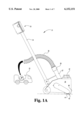
- FIG. 1A is a side view of one embodiment of the present invention.
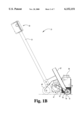
- FIG. 1B is a partially cutaway side view of the device of FIG. 1A;
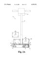
- FIG. 2A is a partially cutaway front view of the device of FIG. 1A;
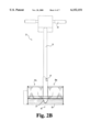
- FIG. 2B is another partially cutaway front view of the device of FIG. 1A with the roller and removable weights removed;
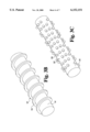
- FIG. 3A is a bottom view of the roller taken in isolation
- FIG. 3B is a perspective view of an alternative roller embodiment taken in isolation
- FIG. 3C is a perspective view of another alternative roller embodiment taken in isolation
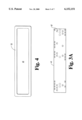
- FIG. 4 is a bottom view of the frame taken in isolation
- FIG. 5 is a side cutaway view showing a roller and suction chamber in engagement with flooded carpet.
- the deflooding device 21 preferably is coupled to a suction pump truck 23 having a pump P therein. Such coupling is by a flexible conduit 25 (shown in FIG. 1A schematically coupled to pump P) coupled to a discharge end of conduit 27 by coupling 29.
- Conduit 25 as illustrated preferably is separate from and not a part of the handle arm 31. Conduit 27 may be very short, even a stub or bayonet coupling to the suction chamber.
- the pump P preferably is a high powered truck-mounted suction system delivering approximately 125 cubic feet per minute as known in the industry.
- portable suction units including ones having lesser cubic feet per minute flow rates, may be located on the job site as well.
- the present invention may be utilized with higher flow rates and/or multiple conduits attached in parallel to the suction chamber, each with the flow rate (such as 125 cfm) thereby providing even greater suction in water removal.
- Device 21 includes a handle arm 31 in the preferred embodiment as shown attached to a control handle 33.
- the arm and handle may take a variety of configurations and preferably, but not necessarily, include actuation controls for advancing and reversing the drive motor/drive system.
- Arm 31 is connected to a housing 35 (see FIG. 1A) with a front face 49.
- housing 35 includes receptacles for weights and/or ballast.
- face 49 is vertical or rearwardly inclined with roller 41 located therealong the front to facilitate water removal next to wells.
- a pair of removable weights 37 and 39 may be lowered into respective weight holders 31a and 39a.
- the collective weight of these weights is in excess of 50 pounds, in excess of 75 pounds, and preferably is about 100 pounds. They are illustrated with handles to facilitate their removal, making relocation of the overall device 21 easier by breaking it down by weight components. Additionally, the weights are preferably located above, and preferably directed above, the compression element, suction roller 41 in the preferred embodiment. As illustrated, roller 41 protrudes below a downward facing opening 43 to facilitate simultaneous compression of the carpet and suction of liquid therefrom.
- other wheels or rollers such as wheel 45 located near the rear of the housing, are provided for operational stability. Such stability preferably includes maintaining suction bar, or frame 53, parallel with the carpet and the floor and level, with the front bar and rear bar thereof maintaining an equivalent seal with the carpet as it slides across the carpet.
- a drive motor such as electric motor 47 (see FIG. 1B), allow for motorized advancement and reversal of the device 21.
- Drive motor 47 is preferably coupled to roller 41 by drive chain or belt 57, shown with a guard, and associated gears or other engagement mechanisms, coupling the gear box from the motor to the roller.
- motor 47 is low voltage (e.g. 20 to 90 volts).
- the drive means may be attached to a separate wheel mechanism, although it is preferred to be attached to the compression roller 41 with the associated weight for engaging traction on the carpet.
- Optional ballast 51 is provided above and around the suction chamber 55, providing further downward force on the roller.
- ballast 51 is steel, stainless steel blocks, or steel shot.
- a suction chamber 55 being defined and enclosed by suction chamber walls 56 is around roller 41 and coupled to conduit 27.
- Suction chamber 55 preferably cylindrical, in the preferred embodiment is defined in its lower most position by frame 53 which acts as a suction bar.
- the bar in the preferred embodiment is formed from round bar stock of about half an inch in diameter. As illustrated, its under surface which contacts the carpet is semi-cylindrical, rounded and smooth to facilitate sliding across the carpet.
- Downward facing opening 43 is ordinarily formed by frame 53 (see FIG. 4).
- Suction chamber 55 is fluid tight and in fluid tight communication by welding or other connection to the intake end of the conduit 27, thereby allowing water intake at opening 43 and discharge at the point of coupling 29.
- Roller 41 is wider than its diameter and rotates about a horizontal axis rotation, preferably about roller axle 61 which rotates in bearing and support assembly 63 and 65.
- roller 41 has a hollow chamber 69 therein (see FIG. 5) whether or not there is a full longitudinal axle or alternatively, stub axles.
- roller 41 has an outside diameter typically ranging between 1.5 and 6 inches, and preferably approximately 2.65 inches and a width preferably of approximately 14.5 inches and is fabricated from 16 gauge stainless steal having a plurality of holes (typically 0.375 inch diameter) therein and spaced at typical spacings of 0.560 inches laterally and 0.45 inches circumferencially, resulting in a perforation density of about 50%.
- FIG. 3A for illustration purposes only has openings, such as the opening 67, shown in parts thereof, it being understood that such openings preferably cover entire surface thereof.
- the openings contribute to the provision of a rigid anti-wave roller which allows the roller to advance across the flooded carpet, compressing the carpet while allowing water to pass through the openings 67 into the hollow chamber 69 of the roller. In this way, the water is not squeegeed or forced forward in a substantial way.
- roller 41 at its lowest most location protrudes beneath the bottom of bar 53 by distance 100. While distance 100 may vary, in the most preferred embodiment distance 100 is approximately a quarter of an inch.
- suction chamber 55 and its defining opening with frame 53, surround the front and back and sides of compression device 41, although it is believed that alternative arrangements including a front and/or back flume, while not preferred, would provide satisfactory results. It is believed that it is preferable to have a reasonably close spacing between the roller and the suction chamber and suction bar so as to concentrate to keep suction flow rate in a narrow area to maintain suction and velocity with such arrangement, including a suction gap along the leading edge. A solid roller is believed to produce satisfactory (although not ideal) results around bar 53 when suction bar is arranged as described and maintained level to form an elevated seal and is surrounded by suction on the front and back. In the preferred embodiment, a distance shown as 101 (see FIG.
- the tangential spacing between the outer surface of roller 41 and frame 53 is typically less than or equal one quarter of an inch. Such spacing can vary to half an inch, and believed to vary outwards of one to two inches depending on variables such as the amount of water removal desired and suction flow rated applied.
- roller 41 also provide the additional benefit of traction as the roller is advanced along the carpet by the drive system.
- the self-propelled aspect of the invention is advantageous, with roller RPM of 1 to 60, and more preferably about 14 to 35 RPM, working well for water removal.
- Alternative embodiments of the anti-wave roller concept are disclosed in the rigid rollers shown in FIGS. 3B and 3C.
- FIG. 3B consists of a roller 141 having rigid protrusion 155.
- protrusion 155 is configured like a helical worm gear and is rigid so as to allow the weights to exert downward compressive force on the carpet nap through protrusion 155 while allowing interstitial chamber 167 to reside therebetween so as to prevent the roller from acting as a wave-creating squeegee.
- Variations on the same include varying worm gear pitches as well as interstitial breaking of the helical worm gear portion 155.
- FIG. 3C discloses another anti-wave roller 241 including a plurality of rigid protuberances 255 with water chamber 267 being defined by the interstitial spaces there between. The number.
- protuberances 255 can be increased and modified according to design to allow the roller to advance across the carpet and compress the carpet nap without pushing the water out in front of the suction take-up.
- protuberance 155 and 255 projecting beneath opening 43 defined in the suction chamber, preferrably a distance about equal to or greater than distance 100.
- protuberances also provide the carpet traction function with the carpet nap.
- Anti-wave carpet compression may also be achieved by a series of parallel banana-shaped bars at the bottom of opening 43 which act as skids along the bottom of the opening, imparting the downward compressive force on the carpet nap without creating a water wave in front of the suction chamber. Variations on these geometries may be included, such as a roller comprising a cylindrical cage structure, it being preferable that the components be made of stainless steal or other rigid material for durability and compressive attributes on the carpet nap.
- weights 37 and 39 are replaced with an operator seat mounted to the unit so as to exert force above, and preferably directly above, roller 41.
- the weights may be replaced with a hollow water chamber.
- Such chamber may be fillable and/or may be in line with the suction conduit path (at least temporarily) to allow priming and filling by the operator initially with the water on the job site, thereby mitigating the weight of the unit when empty for transportation purposes.
Abstract
Description
Claims (20)
Priority Applications (3)
| Application Number | Priority Date | Filing Date | Title |
|---|---|---|---|
| US09/357,558 US6152151A (en) | 1999-07-20 | 1999-07-20 | Device and method for liquid removal from carpet |
| PCT/US2000/019891 WO2001005290A1 (en) | 1999-07-20 | 2000-07-20 | Device and method for liquid removal from carpet |
| AU63606/00A AU6360600A (en) | 1999-07-20 | 2000-07-20 | Device and method for liquid removal from carpet |
Applications Claiming Priority (1)
| Application Number | Priority Date | Filing Date | Title |
|---|---|---|---|
| US09/357,558 US6152151A (en) | 1999-07-20 | 1999-07-20 | Device and method for liquid removal from carpet |
Publications (1)
| Publication Number | Publication Date |
|---|---|
| US6152151A true US6152151A (en) | 2000-11-28 |
Family
ID=23406101
Family Applications (1)
| Application Number | Title | Priority Date | Filing Date |
|---|---|---|---|
| US09/357,558 Expired - Lifetime US6152151A (en) | 1999-07-20 | 1999-07-20 | Device and method for liquid removal from carpet |
Country Status (3)
| Country | Link |
|---|---|
| US (1) | US6152151A (en) |
| AU (1) | AU6360600A (en) |
| WO (1) | WO2001005290A1 (en) |
Cited By (15)
| Publication number | Priority date | Publication date | Assignee | Title |
|---|---|---|---|---|
| US6263539B1 (en) * | 1999-12-23 | 2001-07-24 | Taf Baig | Carpet/floor cleaning wand and machine |
| US6355112B1 (en) | 2000-08-04 | 2002-03-12 | Dri-Eaz Products, Inc. | Systems and methods for extracting liquid from floor coverings |
| US20030056317A1 (en) * | 2001-09-27 | 2003-03-27 | Merck Christoper T. | Water extraction device |
| US6629333B2 (en) | 2000-07-20 | 2003-10-07 | Kurt E. Bolden | Device and method for liquid removal from carpet |
| US7761955B1 (en) | 2007-08-30 | 2010-07-27 | Hiltz Erik D | Dual port cleaning and extraction apparatus |
| US8171598B1 (en) | 2010-07-26 | 2012-05-08 | Erik Daniel Hiltz | Dual port cleaning and extraction apparatus |
| USD684737S1 (en) | 2011-08-31 | 2013-06-18 | Dri-Eaz Products, Inc. | Extractor housing |
| US8510902B2 (en) | 2007-12-03 | 2013-08-20 | Dri-Eaz Products, Inc. | Air induction hard surface cleaning tool with an internal baffle |
| USD701661S1 (en) | 2012-09-04 | 2014-03-25 | Dri-Eaz Products, Inc. | Extractor port housing |
| ITMI20130970A1 (en) * | 2013-06-13 | 2014-12-14 | Ghibli S P A | HEAD DOUBLE CLEANER FOR SURFACE CLEANING MACHINE |
| US9195238B2 (en) | 2012-06-15 | 2015-11-24 | Sapphire Scientific, Inc. | Waste water vessels with multiple valved chambers, and associated systems and methods |
| US9351622B2 (en) | 2012-09-04 | 2016-05-31 | Sapphire Scientific Inc. | Fluid extracting device with shaped head and associated systems and methods of use and manufacture |
| US9700185B1 (en) * | 2015-06-11 | 2017-07-11 | Joe Ray Roberts | Rug cleaning apparatus to rinse, decontaminate and evacuate fluids and undesirable particulates |
| US10060641B2 (en) | 2015-02-25 | 2018-08-28 | Dri-Eaz Products, Inc. | Systems and methods for drying roofs |
| WO2023046212A1 (en) * | 2021-09-26 | 2023-03-30 | 苏州尚腾科技制造有限公司 | Floor mopping mechanism for floor mopping machine, and water spraying and supplementing mode thereof |
Citations (21)
| Publication number | Priority date | Publication date | Assignee | Title |
|---|---|---|---|---|
| US1240799A (en) * | 1917-01-30 | 1917-09-18 | Bon Aurora Mfg And Machine Company | Carpet washing and rinsing machine. |
| US1527828A (en) * | 1922-10-23 | 1925-02-24 | Charles H Barr | Vacuum cleaner |
| US1601774A (en) * | 1925-03-12 | 1926-10-05 | Carl F Scheffer | Vacuum tool |
| US3218876A (en) * | 1963-07-15 | 1965-11-23 | Hoover Co | Variable speed power propelled appliances |
| GB1209341A (en) * | 1967-01-05 | 1970-10-21 | Werner & Mertz Gmbh | Mixing method and apparatus |
| US3683447A (en) * | 1970-06-25 | 1972-08-15 | Minnesota Mining & Mfg | Water removing device |
| US3936199A (en) * | 1971-12-28 | 1976-02-03 | Leifheit International Gunter Leifheit Kg | Method of and apparatus for the cleaning of textiles |
| US4000536A (en) * | 1971-05-28 | 1977-01-04 | Nayfa James E | Floor cleaning machine with foam dispensing system |
| US4069540A (en) * | 1976-07-14 | 1978-01-24 | Frank J. Zamboni & Co. | Machine for removing painted stripes from artificial turf |
| US4145823A (en) * | 1978-03-15 | 1979-03-27 | Lucas Paul A | Snow removing device |
| US4210978A (en) * | 1977-12-20 | 1980-07-08 | H. B. Fuller Company | Automatic carpet cleaning machine |
| US4386873A (en) * | 1979-12-19 | 1983-06-07 | Franz Messner | Device for draining sandy ground areas |
| US4441229A (en) * | 1981-04-06 | 1984-04-10 | Monson Clifford L | Rotary cleaner-polisher |
| US4577364A (en) * | 1984-07-06 | 1986-03-25 | Demetriades Peter G | Floor cleaning machine |
| US4595420A (en) * | 1984-10-29 | 1986-06-17 | Williams Iii Robert C | Method and apparatus for cleaning and maintaining carpet |
| US4875246A (en) * | 1988-07-22 | 1989-10-24 | Quad Research, Inc. | Surface treating device |
| US4989293A (en) * | 1989-05-15 | 1991-02-05 | Murali Bashyam | Tennis court drying machine |
| US5067199A (en) * | 1989-10-13 | 1991-11-26 | Jean Alazet | Suction device with a squeegee for eliminating dirty water while cleaning certain surfaces |
| US5357650A (en) * | 1993-05-17 | 1994-10-25 | Finley Bill G | Carpet water remover |
| US5485652A (en) * | 1990-10-02 | 1996-01-23 | Vax Appliances Ltd. | Suction cleaning head |
| US5893216A (en) * | 1997-07-09 | 1999-04-13 | Smith; Terry C. | Wall-drying system |
-
1999
- 1999-07-20 US US09/357,558 patent/US6152151A/en not_active Expired - Lifetime
-
2000
- 2000-07-20 AU AU63606/00A patent/AU6360600A/en not_active Abandoned
- 2000-07-20 WO PCT/US2000/019891 patent/WO2001005290A1/en active Application Filing
Patent Citations (23)
| Publication number | Priority date | Publication date | Assignee | Title |
|---|---|---|---|---|
| US1240799A (en) * | 1917-01-30 | 1917-09-18 | Bon Aurora Mfg And Machine Company | Carpet washing and rinsing machine. |
| US1268962A (en) * | 1917-01-30 | 1918-06-11 | Halla F Gray | Carpet-washing machine. |
| US1283499A (en) * | 1917-01-30 | 1918-11-05 | Halla F Gray | Suction-nozzle for carpet-washing machines. |
| US1527828A (en) * | 1922-10-23 | 1925-02-24 | Charles H Barr | Vacuum cleaner |
| US1601774A (en) * | 1925-03-12 | 1926-10-05 | Carl F Scheffer | Vacuum tool |
| US3218876A (en) * | 1963-07-15 | 1965-11-23 | Hoover Co | Variable speed power propelled appliances |
| GB1209341A (en) * | 1967-01-05 | 1970-10-21 | Werner & Mertz Gmbh | Mixing method and apparatus |
| US3683447A (en) * | 1970-06-25 | 1972-08-15 | Minnesota Mining & Mfg | Water removing device |
| US4000536A (en) * | 1971-05-28 | 1977-01-04 | Nayfa James E | Floor cleaning machine with foam dispensing system |
| US3936199A (en) * | 1971-12-28 | 1976-02-03 | Leifheit International Gunter Leifheit Kg | Method of and apparatus for the cleaning of textiles |
| US4069540A (en) * | 1976-07-14 | 1978-01-24 | Frank J. Zamboni & Co. | Machine for removing painted stripes from artificial turf |
| US4210978A (en) * | 1977-12-20 | 1980-07-08 | H. B. Fuller Company | Automatic carpet cleaning machine |
| US4145823A (en) * | 1978-03-15 | 1979-03-27 | Lucas Paul A | Snow removing device |
| US4386873A (en) * | 1979-12-19 | 1983-06-07 | Franz Messner | Device for draining sandy ground areas |
| US4441229A (en) * | 1981-04-06 | 1984-04-10 | Monson Clifford L | Rotary cleaner-polisher |
| US4577364A (en) * | 1984-07-06 | 1986-03-25 | Demetriades Peter G | Floor cleaning machine |
| US4595420A (en) * | 1984-10-29 | 1986-06-17 | Williams Iii Robert C | Method and apparatus for cleaning and maintaining carpet |
| US4875246A (en) * | 1988-07-22 | 1989-10-24 | Quad Research, Inc. | Surface treating device |
| US4989293A (en) * | 1989-05-15 | 1991-02-05 | Murali Bashyam | Tennis court drying machine |
| US5067199A (en) * | 1989-10-13 | 1991-11-26 | Jean Alazet | Suction device with a squeegee for eliminating dirty water while cleaning certain surfaces |
| US5485652A (en) * | 1990-10-02 | 1996-01-23 | Vax Appliances Ltd. | Suction cleaning head |
| US5357650A (en) * | 1993-05-17 | 1994-10-25 | Finley Bill G | Carpet water remover |
| US5893216A (en) * | 1997-07-09 | 1999-04-13 | Smith; Terry C. | Wall-drying system |
Cited By (20)
| Publication number | Priority date | Publication date | Assignee | Title |
|---|---|---|---|---|
| US6263539B1 (en) * | 1999-12-23 | 2001-07-24 | Taf Baig | Carpet/floor cleaning wand and machine |
| US6629333B2 (en) | 2000-07-20 | 2003-10-07 | Kurt E. Bolden | Device and method for liquid removal from carpet |
| US6355112B1 (en) | 2000-08-04 | 2002-03-12 | Dri-Eaz Products, Inc. | Systems and methods for extracting liquid from floor coverings |
| US20030056317A1 (en) * | 2001-09-27 | 2003-03-27 | Merck Christoper T. | Water extraction device |
| US6952858B2 (en) | 2001-09-27 | 2005-10-11 | Merck Christopher T | Water extraction device |
| US7761955B1 (en) | 2007-08-30 | 2010-07-27 | Hiltz Erik D | Dual port cleaning and extraction apparatus |
| US8510902B2 (en) | 2007-12-03 | 2013-08-20 | Dri-Eaz Products, Inc. | Air induction hard surface cleaning tool with an internal baffle |
| US9066647B2 (en) | 2007-12-03 | 2015-06-30 | Dri-Eaz Products, Inc. | Air induction hard surface cleaning tools with an internal baffle |
| US8171598B1 (en) | 2010-07-26 | 2012-05-08 | Erik Daniel Hiltz | Dual port cleaning and extraction apparatus |
| USD684737S1 (en) | 2011-08-31 | 2013-06-18 | Dri-Eaz Products, Inc. | Extractor housing |
| US9195238B2 (en) | 2012-06-15 | 2015-11-24 | Sapphire Scientific, Inc. | Waste water vessels with multiple valved chambers, and associated systems and methods |
| USD701661S1 (en) | 2012-09-04 | 2014-03-25 | Dri-Eaz Products, Inc. | Extractor port housing |
| US9351622B2 (en) | 2012-09-04 | 2016-05-31 | Sapphire Scientific Inc. | Fluid extracting device with shaped head and associated systems and methods of use and manufacture |
| ITMI20130970A1 (en) * | 2013-06-13 | 2014-12-14 | Ghibli S P A | HEAD DOUBLE CLEANER FOR SURFACE CLEANING MACHINE |
| WO2014199216A1 (en) * | 2013-06-13 | 2014-12-18 | Ghibli S.P.A. | Double wiper cleansing head for a scrubbing machine for cleaning surfaces |
| US10060641B2 (en) | 2015-02-25 | 2018-08-28 | Dri-Eaz Products, Inc. | Systems and methods for drying roofs |
| US10753628B2 (en) | 2015-02-25 | 2020-08-25 | Legend Brands, Inc. | Systems and methods for drying roofs |
| US11686482B2 (en) | 2015-02-25 | 2023-06-27 | Legend Brands, Inc. | Systems and methods for drying roofs |
| US9700185B1 (en) * | 2015-06-11 | 2017-07-11 | Joe Ray Roberts | Rug cleaning apparatus to rinse, decontaminate and evacuate fluids and undesirable particulates |
| WO2023046212A1 (en) * | 2021-09-26 | 2023-03-30 | 苏州尚腾科技制造有限公司 | Floor mopping mechanism for floor mopping machine, and water spraying and supplementing mode thereof |
Also Published As
| Publication number | Publication date |
|---|---|
| WO2001005290A1 (en) | 2001-01-25 |
| AU6360600A (en) | 2001-02-05 |
| WO2001005290B1 (en) | 2001-03-15 |
Similar Documents
| Publication | Publication Date | Title |
|---|---|---|
| US6629333B2 (en) | Device and method for liquid removal from carpet | |
| US6152151A (en) | Device and method for liquid removal from carpet | |
| CA2264999C (en) | Mobile walk-behind sweeper | |
| US6942790B1 (en) | Open-air filtration cleaning device for pools and hot tubs | |
| US5287581A (en) | Cleaning device having at least one rotating cylindrical sponge | |
| USRE45852E1 (en) | Swimming pool cleaning device | |
| US4893375A (en) | Dual mode floor scrubbing machine | |
| US4329756A (en) | Hot water extraction carpet and floor cleaning machine | |
| CA2626233C (en) | A debris collection device for collecting debris with limited dispersion of airborne particles | |
| US5203047A (en) | Cleaning apparatus with rotatable endless belt | |
| US6049943A (en) | Machine for removing water from outdoor surfaces | |
| JPH04226619A (en) | Self-propelled cleaner | |
| GB1049591A (en) | Improvements in surface cleaning machines | |
| US5579555A (en) | Squeegee assembly for floor cleaning machine | |
| CN1605399B (en) | Portable cleaning machine | |
| US4170805A (en) | Window glass-cleaning device | |
| US5613270A (en) | Motorless floor washing machine | |
| US5336403A (en) | Submersible swimming pool cleaner | |
| US4318202A (en) | Conversion device for cannister vacuum cleaners | |
| US2718656A (en) | Window glass cleaner | |
| CN1535122A (en) | Apparatus for cleaning surfaces with automatic water supply and drain | |
| US4799286A (en) | Power driven vacuum sweeper | |
| US3688338A (en) | Carpet cleaning apparatuses | |
| US8505156B2 (en) | Floor cleaning apparatus with surface dryer | |
| US8185995B2 (en) | Portable surface treating apparatus |
Legal Events
| Date | Code | Title | Description |
|---|---|---|---|
| AS | Assignment |
Owner name: BOLDEN'S MANUFACTURING, INC., INDIANA Free format text: ASSIGNMENT OF ASSIGNORS INTEREST;ASSIGNORS:BOLDEN, KURT E.;SUTTON, DAVE, SR.;REEL/FRAME:010125/0366 Effective date: 19990720 |
|
| STCF | Information on status: patent grant |
Free format text: PATENTED CASE |
|
| FPAY | Fee payment |
Year of fee payment: 4 |
|
| AS | Assignment |
Owner name: BOU-MATIC TECHNOLOGIES, LLC, LOUISIANA Free format text: ASSIGNMENT OF ASSIGNORS INTEREST;ASSIGNOR:BOLDEN'S MANUFACTURING, INC.;REEL/FRAME:016026/0049 Effective date: 20041028 |
|
| AS | Assignment |
Owner name: BOU-MATIC TECHNOLOGIES, LLC, TEXAS Free format text: ASSIGNMENT OF ASSIGNORS INTEREST;ASSIGNOR:BOLDEN'S MANUFACTURING, INC.;REEL/FRAME:018847/0014 Effective date: 20041101 |
|
| FEPP | Fee payment procedure |
Free format text: PAT HOLDER NO LONGER CLAIMS SMALL ENTITY STATUS, ENTITY STATUS SET TO UNDISCOUNTED (ORIGINAL EVENT CODE: STOL); ENTITY STATUS OF PATENT OWNER: LARGE ENTITY |
|
| REFU | Refund |
Free format text: REFUND - PAYMENT OF MAINTENANCE FEE, 8TH YR, SMALL ENTITY (ORIGINAL EVENT CODE: R2552); ENTITY STATUS OF PATENT OWNER: LARGE ENTITY |
|
| FPAY | Fee payment |
Year of fee payment: 8 |
|
| FEPP | Fee payment procedure |
Free format text: ENTITY STATUS SET TO UNDISCOUNTED (ORIGINAL EVENT CODE: BIG.); ENTITY STATUS OF PATENT OWNER: LARGE ENTITY |
|
| FPAY | Fee payment |
Year of fee payment: 12 |
|
| AS | Assignment |
Owner name: TECHNOLOGIES HOLDINGS CORP., TEXAS Free format text: ASSIGNMENT OF ASSIGNORS INTEREST;ASSIGNOR:BOU-MATIC TECHNOLOGIES, LLC;REEL/FRAME:044221/0666 Effective date: 20171124 |
|
| AS | Assignment |
Owner name: THERMA-STOR LLC, WISCONSIN Free format text: ASSIGNMENT OF ASSIGNORS INTEREST;ASSIGNORS:TECHNOLOGIES HOLDINGS CORP.;THERMA-STOR LLC;REEL/FRAME:044997/0596 Effective date: 20171130 |
|
| AS | Assignment |
Owner name: THERMA-STOR LLC, WISCONSIN Free format text: ASSIGNMENT OF ASSIGNORS INTEREST;ASSIGNOR:TECHNOLOGIES HOLDINGS CORP.;REEL/FRAME:045003/0972 Effective date: 20171130 |
|
| AS | Assignment |
Owner name: CIBC BANK USA, ILLINOIS Free format text: SECURITY INTEREST;ASSIGNOR:THERMA-STOR LLC;REEL/FRAME:045021/0635 Effective date: 20171130 |
|
| AS | Assignment |
Owner name: THERMA-STOR LLC, WISCONSIN Free format text: RELEASE BY SECURED PARTY;ASSIGNOR:CIBC BANK USA;REEL/FRAME:046226/0880 Effective date: 20180503 Owner name: CIBC BANK USA, ILLINOIS Free format text: SECURITY INTEREST;ASSIGNOR:THERMA-STOR LLC;REEL/FRAME:046227/0045 Effective date: 20180503 |