US6152176A - Air valve structure for alternately aerated three-pipe style air bed - Google Patents
Air valve structure for alternately aerated three-pipe style air bed Download PDFInfo
- Publication number
- US6152176A US6152176A US09/336,346 US33634699A US6152176A US 6152176 A US6152176 A US 6152176A US 33634699 A US33634699 A US 33634699A US 6152176 A US6152176 A US 6152176A
- Authority
- US
- United States
- Prior art keywords
- air
- rotation seat
- pipes
- pipe
- intake
- Prior art date
- Legal status (The legal status is an assumption and is not a legal conclusion. Google has not performed a legal analysis and makes no representation as to the accuracy of the status listed.)
- Expired - Lifetime
Links
Images

Classifications
-
- A—HUMAN NECESSITIES
- A61—MEDICAL OR VETERINARY SCIENCE; HYGIENE
- A61G—TRANSPORT, PERSONAL CONVEYANCES, OR ACCOMMODATION SPECIALLY ADAPTED FOR PATIENTS OR DISABLED PERSONS; OPERATING TABLES OR CHAIRS; CHAIRS FOR DENTISTRY; FUNERAL DEVICES
- A61G7/00—Beds specially adapted for nursing; Devices for lifting patients or disabled persons
- A61G7/05—Parts, details or accessories of beds
- A61G7/057—Arrangements for preventing bed-sores or for supporting patients with burns, e.g. mattresses specially adapted therefor
- A61G7/05769—Arrangements for preventing bed-sores or for supporting patients with burns, e.g. mattresses specially adapted therefor with inflatable chambers
- A61G7/05776—Arrangements for preventing bed-sores or for supporting patients with burns, e.g. mattresses specially adapted therefor with inflatable chambers with at least two groups of alternately inflated chambers
-
- F—MECHANICAL ENGINEERING; LIGHTING; HEATING; WEAPONS; BLASTING
- F16—ENGINEERING ELEMENTS AND UNITS; GENERAL MEASURES FOR PRODUCING AND MAINTAINING EFFECTIVE FUNCTIONING OF MACHINES OR INSTALLATIONS; THERMAL INSULATION IN GENERAL
- F16K—VALVES; TAPS; COCKS; ACTUATING-FLOATS; DEVICES FOR VENTING OR AERATING
- F16K11/00—Multiple-way valves, e.g. mixing valves; Pipe fittings incorporating such valves
- F16K11/02—Multiple-way valves, e.g. mixing valves; Pipe fittings incorporating such valves with all movable sealing faces moving as one unit
- F16K11/06—Multiple-way valves, e.g. mixing valves; Pipe fittings incorporating such valves with all movable sealing faces moving as one unit comprising only sliding valves, i.e. sliding closure elements
- F16K11/072—Multiple-way valves, e.g. mixing valves; Pipe fittings incorporating such valves with all movable sealing faces moving as one unit comprising only sliding valves, i.e. sliding closure elements with pivoted closure members
- F16K11/076—Multiple-way valves, e.g. mixing valves; Pipe fittings incorporating such valves with all movable sealing faces moving as one unit comprising only sliding valves, i.e. sliding closure elements with pivoted closure members with sealing faces shaped as surfaces of solids of revolution
-
- Y—GENERAL TAGGING OF NEW TECHNOLOGICAL DEVELOPMENTS; GENERAL TAGGING OF CROSS-SECTIONAL TECHNOLOGIES SPANNING OVER SEVERAL SECTIONS OF THE IPC; TECHNICAL SUBJECTS COVERED BY FORMER USPC CROSS-REFERENCE ART COLLECTIONS [XRACs] AND DIGESTS
- Y10—TECHNICAL SUBJECTS COVERED BY FORMER USPC
- Y10T—TECHNICAL SUBJECTS COVERED BY FORMER US CLASSIFICATION
- Y10T137/00—Fluid handling
- Y10T137/8593—Systems
- Y10T137/86389—Programmer or timer
-
- Y—GENERAL TAGGING OF NEW TECHNOLOGICAL DEVELOPMENTS; GENERAL TAGGING OF CROSS-SECTIONAL TECHNOLOGIES SPANNING OVER SEVERAL SECTIONS OF THE IPC; TECHNICAL SUBJECTS COVERED BY FORMER USPC CROSS-REFERENCE ART COLLECTIONS [XRACs] AND DIGESTS
- Y10—TECHNICAL SUBJECTS COVERED BY FORMER USPC
- Y10T—TECHNICAL SUBJECTS COVERED BY FORMER US CLASSIFICATION
- Y10T137/00—Fluid handling
- Y10T137/8593—Systems
- Y10T137/86493—Multi-way valve unit
- Y10T137/86549—Selective reciprocation or rotation
-
- Y—GENERAL TAGGING OF NEW TECHNOLOGICAL DEVELOPMENTS; GENERAL TAGGING OF CROSS-SECTIONAL TECHNOLOGIES SPANNING OVER SEVERAL SECTIONS OF THE IPC; TECHNICAL SUBJECTS COVERED BY FORMER USPC CROSS-REFERENCE ART COLLECTIONS [XRACs] AND DIGESTS
- Y10—TECHNICAL SUBJECTS COVERED BY FORMER USPC
- Y10T—TECHNICAL SUBJECTS COVERED BY FORMER US CLASSIFICATION
- Y10T137/00—Fluid handling
- Y10T137/8593—Systems
- Y10T137/86493—Multi-way valve unit
- Y10T137/86558—Plural noncommunicating flow paths
-
- Y—GENERAL TAGGING OF NEW TECHNOLOGICAL DEVELOPMENTS; GENERAL TAGGING OF CROSS-SECTIONAL TECHNOLOGIES SPANNING OVER SEVERAL SECTIONS OF THE IPC; TECHNICAL SUBJECTS COVERED BY FORMER USPC CROSS-REFERENCE ART COLLECTIONS [XRACs] AND DIGESTS
- Y10—TECHNICAL SUBJECTS COVERED BY FORMER USPC
- Y10T—TECHNICAL SUBJECTS COVERED BY FORMER US CLASSIFICATION
- Y10T137/00—Fluid handling
- Y10T137/8593—Systems
- Y10T137/86493—Multi-way valve unit
- Y10T137/86574—Supply and exhaust
- Y10T137/86638—Rotary valve
Definitions
- the present invention is related to an air valve structure for an alternately aerated three-pipe style air bed. And especially to an air valve structure for an air bed having three sets of mutually separated elongate air bladders which can be alternately aerated, discharged or can be all aerated.
- a conventional air bed is generally provided with two sets of elongate air bladders.
- the air bladders are operated like this: the air bladders are both aerated, or the air bladders of odd number are aerated while the air bladders of even number are discharged, or the airbladders of odd number are discharged while the air bladders of even number are aerated.
- the conventional air bed only provided with two sets of elongate air bladders does not meet the practical requirement in consideration of the contact areas of the body of a patient with the air bed.
- an air bed provided with three sets of mutually separated elongate air bladders capable of alternate aeration and discharging is requisite to reduce the distances between every two air bladders being aerated and to more effectively change contact areas of the body of a patient with the air bed to lower the chance of getting decubitus.
- the object of the present invention is to provide an air bed structure which is provided at least with three air pipes.
- the three air air pipes are connected respectively to the three sets of mutually separated elongate air bladders. In this way, by rotation of the air valve, the object to alternately aerate and discharge part of or aerate all the air bladders can be achieved.
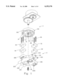
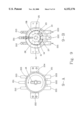
- FIG. 1 is an analytic perspective view of the present invention
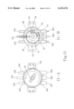
- FIG. 2 is another analytic perspective view of the present invention.
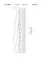
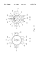
- FIG. 3 (including FIGS. 3-1 and 3-2) is a schematic view showing operation of the structure of the present invention
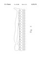
- FIG. 4 is a schematic view showing the air bed of FIG. 3;
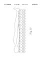
- FIG. 5 (including FIGS. 5-1 and 5-2) is another schematic view showing operation of the structure of the present invention.
- FIG. 6 is a schematic view showing the air bed of FIG. 5;
- FIG. 7 (including FIGS. 7-1 and 7-2) is another schematic view showing operation of the structure of the present invention.
- FIG. 8 is a schematic view showing the air bed of FIG. 7;
- FIG. 9 (including FIGS. 9-1 and 9-2) is a further schematic view showing operation of the structure of the present invention.
- FIG. 10 is a schematic view showing the air bed of FIG. 9;
- FIG. 11 (including FIGS. 11-1 and 11-2) is a further schematic view showing operation of the structure of the present invention.
- FIG. 12 is a schematic view showing the air bed of FIG. 11;
- FIG. 13 (including FIGS. 13-1 and 13-2) is another schematic view showing operation of the structure of the present invention.
- FIG. 14 is a schematic view showing the air bed of FIG. 13.
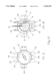
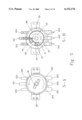
- the air valve of the present invention is comprised mainly of an upper rotation seat 1, a lower rotation seat 2 and a plurality of micro-switches 31, 32, 33 and 34.
- the upper rotation seat 1 is placed over the lower rotation seat 2, the top of the upper rotation seat 1 is a sealed plane surface and is provided with an upper axle hole 10.
- the bottom of the upper axle hole 10 is surrounded by an upper inner intake chamber 11 which is surrounded by an upper external discharge chamber 12.
- Two stop blocks 13, 14 are provided between the upper inner intake chamber 11 and the upper external discharge chamber 12.
- a notch 121 is formed between the stop blocks 13, 14 and is communicated with the upper external discharge chamber 12.
- a plurality of lugs 151, 152, 153 and 154 at different levels are provided at suitable positions on the exterior surface of the upper rotation seat 1.
- a driving groove 16 is provided at the upper axle hole 10 on the top of the upper rotation seat 1.
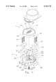
- the lower rotation seat 2 provided beneath the upper rotation seat 1 is shaped similar to the upper rotation seat 1, and is provided at the center thereof with a lower axle hole 20.
- a middle intake pipe 211, a discharge pipe 212 and a discharge pipe 213 are provided horizontally at one side on the exterior wall of the lower rotation seat 2.
- three air pipes 221, 222, 223 are provided at the other side on the exterior wall of the lower rotation seat 2.
- An annular air chamber 23 is provided surrounding the lower axle hole 20 and is communicated with the interior of the middle intake pipe 211 through a middle air hole 2110.
- the annular air chamber 23 is provided at a plurality of suitable positions with three intake pipes 26, 27 and 28 communicated respectively with the interiors of the three air pipes 221, 222, 223.
- Two discharge chambers 24, 25 are provided at the lateral sides of the lower rotation seat 2 adjacent to the intake pipes 26, and 28 and are communicated with the discharge pipes 212 and 213 through two air holes 2120 and 2130 respectively. Further, two switch seats 291, 292 are symmetrically provided on the lateral sides of the lower rotation seat 2. An air pipe 2115 extending downwards is communicated with the middle intake pipe 211.
- micro-switches 31, 32 and 33, 34 appropriately provided on the switch seats 291, 292 respectively and locked with a plurality of locking members 35.
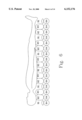
- FIG. 4 which is a schematic view showing an air bed 9, the bottom of the air bed 9 is provided with a bottom cushion 94 which is aerated permanently.
- a plurality of elongate air bladders 91, 92, 93 are mutually parallelly separated and mounted on the bottom cushion 94.
- the middle intake pipe 211 is connected exteriorly to a pump (not shown) for air intake.
- the air pipes 221,222, 223 are connected respectively to the elongate air bladders 91, 92, 93, while the bottom cushion 94 is communicated with the air pipe 2115 on the lower rotation seat 2. That is, the middle intake pipe 211 can always supply air for the bottom cushion 94 through the air pipe 2115 to keep it in an aerated state.
- micro-switches 31, 32 and 33, 34 and four lugs 151, 152, 153 and 154 is for the purpose of controlling rotation and time of stopping of the upper rotation seat 1 in pursuance of a computer software program.
- the motor stops rotating, say, it stops for an appropriate period of time and then rotates again to proceed the next stroke.
- intake air flows in the following sequence: it flows from the middle intake pipe 211 through the annular air chamber 23, the three intake pipes 26, 27 and 28, and then flows separately to the air pipes 221, 222, 223.
- the elongate air bladders 91, 92, 93 are all supplied with air, such as is shown in FIG. 4, at this time, the discharge pipes 212 and 213 are inactive.
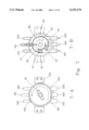
- the upper rotation seat 1 After a given time period, the upper rotation seat 1 will be activated by the motor to rotate from the position shown in FIG. 3 to that shown in FIG. 5. At this time, intake air flows in the following sequence: it flows from the middle intake pipe 211 through the annular air chamber 23, the upper inner intake chamber 11, the intake pipes 27 and 28, and then flows separately to the air pipes 222, 223. In this way, the elongate air bladders 92, 93 are both supplied with air, while the intake pipe 26 does not have air intake for it is not covered by the upper inner intake chamber 11. The notch 121 on the upper rotation seat 1 laps the intake pipe 26 now.
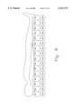
- the elongate air bladder 91 So that air originally in the elongate air bladder 91 flows through the air pipe 221 back to the intake pipe 26, the notch 121, the upper external discharge chamber 12, the discharge chamber 24, 25 and is discharged out of the discharge pipes 212 and 213. Therefore, the elongate air bladder 91 is in the state of discharging, while the elongate air bladders 92, 93 are aerated (as is shown in FIG. 6).
- the upper rotation seat 1 will be activated by the motor to rotate from the position shown in FIG. 5 to that shown in FIG. 7.
- intake air flows in the following sequence: it flows from the middle intake pipe 211 through the annular air chamber 23, the upper inner intake chamber 11, the intake pipes 26, 27 and 28, and then flows separately to the air pipes 221, 222, 223.
- the elongate air bladders 91, 92, 93 are all supplied with air. This is shown in FIG. 8, the elongate air bladders 91, 92, 93 are all aerated, while the discharge pipes 212 and 213 are inactive.
- the upper rotation seat 1 will be activated by the motor to rotate from the position shown in FIG. 7 to that shown in FIG. 9.
- intake air flows in the following sequence: it flows from the middle intake pipe 211 through the annular air chamber 23, the upper inner intake chamber 11, the intake pipes 26 and 28, and then flows separately to the air pipes 221 and 223.
- the elongate air bladders 91 and 93 are both supplied with air, while the intake pipe 27 does not have air intake for it is not covered by the upper inner intake chamber 11.
- the notch 121 on the upper rotation seat 1 laps the intake pipe 27 now.
- the elongate air bladder 92 So that air originally in the elongate air bladder 92 flows through the air pipe 222 back to the intake pipe 27, the notch 121, the upper external discharge chamber 12, the discharge chamber 24, 25 and is discharged out of the discharge pipes 212 and 213. Therefore, the elongate air bladder 92 is in the state of discharging, while the elongate air bladders 91, 93 are aerated (as is shown in FIG. 10).
- the upper rotation seat 1 will be activated by the motor to rotate from the position shown in FIG. 9 to that shown in FIG. 11.
- intake air flows in the following sequence: it flows from the middle intake pipe 211 through the annular air chamber 23, the upper inner intake chamber 11, the intake pipes 26, 27 and 28, and then flows separately to the air pipes 221, 222, 223.
- the elongate air bladders 91, 92, 93 are all supplied with air. This is shown in FIG. 12, the elongate air bladders 91, 92, 93 are all aerated, while the discharge pipes 212 and 213 are inactive.
- the upper rotation seat 1 will be activated by the motor to rotate from the position shown in FIG. 11 to that shown in FIG. 13.
- intake air flows in the following sequence: it flows from the middle intake pipe 211 through the annular air chamber 23, the upper inner intake chamber 11, the intake pipes 26 and 27, and then flows separately to the air pipes 221 and 222.
- the elongate air bladders 91 and 92 are both supplied with air, while the intake pipe 28 does not have air intake for it is not covered by the upper inner intake chamber 11.
- the notch 121 on the upper rotation seat 1 laps the intake pipe 28 now.
- the elongate air bladder 93 So that air originally in the elongate air bladder 93 flows through the air pipe 223 back to the intake pipe 28, the notch 121, the upper external discharge chamber 12, the discharge chamber 24, 25 and is discharged out of the discharge pipes 212 and 213. Therefore, the elongate air bladder 93 is in the state of discharging, while the elongate air bladders 91, 92 are aerated (as is shown in FIG. 14).
- the air valve structure for an alternately aerated three-pipe style air bed of the present invention mainly uses the upper rotation seat 1, the lower rotation seat 2 and a plurality of micro-switches 31, 32 and 33, 34 to get the object of alternate aerating, discharging part of or aerating all the elongate air bladders 91, 92, 93.
- Such effect can not be achieved with any product existed in the markets.
- the product of the present invention has never been disclosed in a document or existed in the markets and hence is practical, novel and improved.
Abstract
An air valve structure for an alternately aerated three-pipe style air bed, being comprised of an upper rotation seat and a lower rotation seat, three air pipes on the air valve structure can be supplied with air through relative rotation between and by the unique structural design of the upper rotation seat and the lower rotation seat,
Description
1. Field of the Invention
The present invention is related to an air valve structure for an alternately aerated three-pipe style air bed. And especially to an air valve structure for an air bed having three sets of mutually separated elongate air bladders which can be alternately aerated, discharged or can be all aerated.
2. Description of the Prior Art
A conventional air bed is generally provided with two sets of elongate air bladders. The air bladders are operated like this: the air bladders are both aerated, or the air bladders of odd number are aerated while the air bladders of even number are discharged, or the airbladders of odd number are discharged while the air bladders of even number are aerated. However, the conventional air bed only provided with two sets of elongate air bladders does not meet the practical requirement in consideration of the contact areas of the body of a patient with the air bed. In view of this, an air bed provided with three sets of mutually separated elongate air bladders capable of alternate aeration and discharging is requisite to reduce the distances between every two air bladders being aerated and to more effectively change contact areas of the body of a patient with the air bed to lower the chance of getting decubitus.
Therefore, the inventor studied and has developed the present invention to obtain a novel air valve, especially a novel air valve used on an air bed provided with three sets of mutually separated elongate air bladders capable of alternate aeration and discharging of part of the air bladders or aeration of all air bladders.
The object of the present invention is to provide an air bed structure which is provided at least with three air pipes. The three air air pipes are connected respectively to the three sets of mutually separated elongate air bladders. In this way, by rotation of the air valve, the object to alternately aerate and discharge part of or aerate all the air bladders can be achieved.
The present invention will be apparent in its composition of structure and the effect created after reading the detailed description of the preferred embodiment thereof in reference to the accompanying drawings.
In the drawings:
FIG. 1 is an analytic perspective view of the present invention;
FIG. 2 is another analytic perspective view of the present invention;
FIG. 3 (including FIGS. 3-1 and 3-2) is a schematic view showing operation of the structure of the present invention;
FIG. 4 is a schematic view showing the air bed of FIG. 3;
FIG. 5 (including FIGS. 5-1 and 5-2) is another schematic view showing operation of the structure of the present invention;
FIG. 6 is a schematic view showing the air bed of FIG. 5;
FIG. 7 (including FIGS. 7-1 and 7-2) is another schematic view showing operation of the structure of the present invention;
FIG. 8 is a schematic view showing the air bed of FIG. 7;
FIG. 9 (including FIGS. 9-1 and 9-2) is a further schematic view showing operation of the structure of the present invention;
FIG. 10 is a schematic view showing the air bed of FIG. 9;
FIG. 11 (including FIGS. 11-1 and 11-2) is a further schematic view showing operation of the structure of the present invention;
FIG. 12 is a schematic view showing the air bed of FIG. 11;
FIG. 13 (including FIGS. 13-1 and 13-2) is another schematic view showing operation of the structure of the present invention;
FIG. 14 is a schematic view showing the air bed of FIG. 13.
Referring to FIGS. 1, 2 and 3, the air valve of the present invention is comprised mainly of an upper rotation seat 1, a lower rotation seat 2 and a plurality of micro-switches 31, 32, 33 and 34.
Wherein, the upper rotation seat 1 is placed over the lower rotation seat 2, the top of the upper rotation seat 1 is a sealed plane surface and is provided with an upper axle hole 10. The bottom of the upper axle hole 10 is surrounded by an upper inner intake chamber 11 which is surrounded by an upper external discharge chamber 12. Two stop blocks 13, 14 are provided between the upper inner intake chamber 11 and the upper external discharge chamber 12. A notch 121 is formed between the stop blocks 13, 14 and is communicated with the upper external discharge chamber 12. A plurality of lugs 151, 152, 153 and 154 at different levels are provided at suitable positions on the exterior surface of the upper rotation seat 1. A driving groove 16 is provided at the upper axle hole 10 on the top of the upper rotation seat 1.
The lower rotation seat 2 provided beneath the upper rotation seat 1 is shaped similar to the upper rotation seat 1, and is provided at the center thereof with a lower axle hole 20. A middle intake pipe 211, a discharge pipe 212 and a discharge pipe 213 are provided horizontally at one side on the exterior wall of the lower rotation seat 2. And three air pipes 221, 222, 223 are provided at the other side on the exterior wall of the lower rotation seat 2. An annular air chamber 23 is provided surrounding the lower axle hole 20 and is communicated with the interior of the middle intake pipe 211 through a middle air hole 2110. The annular air chamber 23 is provided at a plurality of suitable positions with three intake pipes 26, 27 and 28 communicated respectively with the interiors of the three air pipes 221, 222, 223. Two discharge chambers 24, 25 are provided at the lateral sides of the lower rotation seat 2 adjacent to the intake pipes 26, and 28 and are communicated with the discharge pipes 212 and 213 through two air holes 2120 and 2130 respectively. Further, two switch seats 291, 292 are symmetrically provided on the lateral sides of the lower rotation seat 2. An air pipe 2115 extending downwards is communicated with the middle intake pipe 211.
There are four micro-switches 31, 32 and 33, 34 appropriately provided on the switch seats 291, 292 respectively and locked with a plurality of locking members 35.
The four micro-switches 31, 32 and 33, 34 are mounted on the lower rotation seat 2, then the upper rotation seat 1 is placed over and mounted on the lower rotation seat 2 to complete the air valve assembly of the present invention. To rotate the upper rotation seat 1 on the lower rotation seat 2, an axle of a motor (not shown) is added externally through the upper axle hole 10 and the lower axle hole 20. And the axle of motor is mounted to make a fixed angle relative to the driving groove 16 of the upper rotation seat 1 to allow rotation of the axle of motor together with the upper rotation seat 1 on the lower rotation seat 2. Also referring to FIG. 4 which is a schematic view showing an air bed 9, the bottom of the air bed 9 is provided with a bottom cushion 94 which is aerated permanently. A plurality of elongate air bladders 91, 92, 93 are mutually parallelly separated and mounted on the bottom cushion 94.
Connecting and operation of the air valve of the present invention are as below: The middle intake pipe 211 is connected exteriorly to a pump (not shown) for air intake. The air pipes 221,222, 223 are connected respectively to the elongate air bladders 91, 92, 93, while the bottom cushion 94 is communicated with the air pipe 2115 on the lower rotation seat 2. That is, the middle intake pipe 211 can always supply air for the bottom cushion 94 through the air pipe 2115 to keep it in an aerated state.
The reason that there are four micro-switches 31, 32 and 33, 34 and four lugs 151, 152, 153 and 154 is for the purpose of controlling rotation and time of stopping of the upper rotation seat 1 in pursuance of a computer software program. Primarily, whenever the lugs 151, 152, 153 and 154 touch the micro-switches 31, 32 and 33, 34 at corresponding levels, themotor stops rotating, say, it stops for an appropriate period of time and then rotates again to proceed the next stroke.
When the air valve of the present invention is in the state as shown in FIG. 3, intake air flows in the following sequence: it flows from the middle intake pipe 211 through the annular air chamber 23, the three intake pipes 26, 27 and 28, and then flows separately to the air pipes 221, 222, 223. In this way, the elongate air bladders 91, 92, 93 are all supplied with air, such as is shown in FIG. 4, at this time, the discharge pipes 212 and 213 are inactive.
After a given time period, the upper rotation seat 1 will be activated by the motor to rotate from the position shown in FIG. 3 to that shown in FIG. 5. At this time, intake air flows in the following sequence: it flows from the middle intake pipe 211 through the annular air chamber 23, the upper inner intake chamber 11, the intake pipes 27 and 28, and then flows separately to the air pipes 222, 223. In this way, the elongate air bladders 92, 93 are both supplied with air, while the intake pipe 26 does not have air intake for it is not covered by the upper inner intake chamber 11. The notch 121 on the upper rotation seat 1 laps the intake pipe 26 now. So that air originally in the elongate air bladder 91 flows through the air pipe 221 back to the intake pipe 26, the notch 121, the upper external discharge chamber 12, the discharge chamber 24, 25 and is discharged out of the discharge pipes 212 and 213. Therefore, the elongate air bladder 91 is in the state of discharging, while the elongate air bladders 92, 93 are aerated (as is shown in FIG. 6).
Further, after a given time period, the upper rotation seat 1 will be activated by the motor to rotate from the position shown in FIG. 5 to that shown in FIG. 7. At this time, intake air flows in the following sequence: it flows from the middle intake pipe 211 through the annular air chamber 23, the upper inner intake chamber 11, the intake pipes 26, 27 and 28, and then flows separately to the air pipes 221, 222, 223. In this way, the elongate air bladders 91, 92, 93 are all supplied with air. This is shown in FIG. 8, the elongate air bladders 91, 92, 93 are all aerated, while the discharge pipes 212 and 213 are inactive.
Further after a given time period, the upper rotation seat 1 will be activated by the motor to rotate from the position shown in FIG. 7 to that shown in FIG. 9. At this time, intake air flows in the following sequence: it flows from the middle intake pipe 211 through the annular air chamber 23, the upper inner intake chamber 11, the intake pipes 26 and 28, and then flows separately to the air pipes 221 and 223. In this way, the elongate air bladders 91 and 93 are both supplied with air, while the intake pipe 27 does not have air intake for it is not covered by the upper inner intake chamber 11. The notch 121 on the upper rotation seat 1 laps the intake pipe 27 now. So that air originally in the elongate air bladder 92 flows through the air pipe 222 back to the intake pipe 27, the notch 121, the upper external discharge chamber 12, the discharge chamber 24, 25 and is discharged out of the discharge pipes 212 and 213. Therefore, the elongate air bladder 92 is in the state of discharging, while the elongate air bladders 91, 93 are aerated (as is shown in FIG. 10).
Again, after a given time period, the upper rotation seat 1 will be activated by the motor to rotate from the position shown in FIG. 9 to that shown in FIG. 11. At this time, intake air flows in the following sequence: it flows from the middle intake pipe 211 through the annular air chamber 23, the upper inner intake chamber 11, the intake pipes 26, 27 and 28, and then flows separately to the air pipes 221, 222, 223. In this way, the elongate air bladders 91, 92, 93 are all supplied with air. This is shown in FIG. 12, the elongate air bladders 91, 92, 93 are all aerated, while the discharge pipes 212 and 213 are inactive.
Further after a given time period, the upper rotation seat 1 will be activated by the motor to rotate from the position shown in FIG. 11 to that shown in FIG. 13. At this time, intake air flows in the following sequence: it flows from the middle intake pipe 211 through the annular air chamber 23, the upper inner intake chamber 11, the intake pipes 26 and 27, and then flows separately to the air pipes 221 and 222. In this way, the elongate air bladders 91 and 92 are both supplied with air, while the intake pipe 28 does not have air intake for it is not covered by the upper inner intake chamber 11. The notch 121 on the upper rotation seat 1 laps the intake pipe 28 now. So that air originally in the elongate air bladder 93 flows through the air pipe 223 back to the intake pipe 28, the notch 121, the upper external discharge chamber 12, the discharge chamber 24, 25 and is discharged out of the discharge pipes 212 and 213. Therefore, the elongate air bladder 93 is in the state of discharging, while the elongate air bladders 91, 92 are aerated (as is shown in FIG. 14).
The sequence of operation as state above can be recurrently continued.
In conclusion, the air valve structure for an alternately aerated three-pipe style air bed of the present invention mainly uses the upper rotation seat 1, the lower rotation seat 2 and a plurality of micro-switches 31, 32 and 33, 34 to get the object of alternate aerating, discharging part of or aerating all the elongate air bladders 91, 92, 93. Such effect can not be achieved with any product existed in the markets. The product of the present invention has never been disclosed in a document or existed in the markets and hence is practical, novel and improved.
Claims (4)
1. An air valve structure for an alternately aerated three-pipe style air bed comprising an upper rotation seat, a lower rotation seat and a plurality of micro-switches, wherein,
said upper rotation seat is placed over said lower rotation seat, the top of said upper rotation seat is a sealed plane surface and is provided with an upper axle hole, the bottom of said upper axle hole is surrounded by an upper inner intake chamber which is surrounded by an upper external discharge chamber, two stop blocks are provided between said upper inner intake chamber and said external discharge chamber, a notch is formed between said stop blocks and is communicated with said external discharge chamber, a plurality of lugs at different levels are provided at suitable positions on the exterior surface of said upper rotation seat, a driving groove is provided at said upper axle hole on the top of said upper rotation seat;
said lower rotation seat provided beneath said upper rotation seat is provided at the center thereof with a lower axle hole, a middle intake pipe and two discharge pipes are provided horizontally at one side on the exterior wall of said lower rotation seat, and three air pipes are provided at the other side on the exterior wall of said lower rotation seat, an annular air chamber is provided surrounding said lower axle hole and is communicated with the interior of said middle intake pipe through a middle air hole, said annular air chamber is provided at a plurality of suitable positions with three intake pipes communicated respectively with the interiors of said three air pipes, two discharge chambers are provided at the lateral sides of said lower rotation seat adjacent to said intake pipes and are communicated with said discharge pipes through two air holes respectively, further, two switch seats are symmetrically provided on the lateral sides of said lower rotation seat;
four micro-switches are provided on said switch seats respectively and are locked with a plurality of locking members;
said four micro-switches are mounted on said lower rotation seat, then said upper rotation seat is placed over and mounted on said lower rotation seat, an axle of a motor is added externally through said upper axle hole and said lower axle hole to rotate said upper rotation seat on said lower rotation seat, and said axle of motor is mounted to make a fixed angle relative to said driving groove of said upper rotation seat to allow rotation of said axle of motor together with said upper rotation seat on said lower rotation seat;
with this arrangement, three sets of elongate air bladders are mutually separated and connected to said three air pipes, said upper rotation seat is activated by said motor to rotate, in this way, said elongate air bladders are all aerated, or alternately aerated and discharged.
2. An air valve structure for an alternately aerated three-pipe style air bed as stated in claim 1, wherein,
when said upper rotation seat rotates, said motor is adapted to be stopped by touching of said lugs with said micro-switches.
3. An air valve structure for an alternately aerated three-pipe style air bed as stated in claim 1, wherein,
an air pipe is communicated with said middle intake pipe for communication with a bottom cushion of said air bed.
4. An air valve structure for an alternately aerated three-pipe style air bed as stated in claim 1, wherein,
amount of both said micro-switches and lugs is four.
Applications Claiming Priority (2)
| Application Number | Priority Date | Filing Date | Title |
|---|---|---|---|
| TW087216745U TW373499U (en) | 1998-10-09 | 1998-10-09 | Air valve structure for the air cushion bed of 3 tubes alternative type |
| TW87216745 | 1998-10-09 |
Publications (1)
| Publication Number | Publication Date |
|---|---|
| US6152176A true US6152176A (en) | 2000-11-28 |
Family
ID=21636715
Family Applications (1)
| Application Number | Title | Priority Date | Filing Date |
|---|---|---|---|
| US09/336,346 Expired - Lifetime US6152176A (en) | 1998-10-09 | 1999-06-18 | Air valve structure for alternately aerated three-pipe style air bed |
Country Status (2)
| Country | Link |
|---|---|
| US (1) | US6152176A (en) |
| TW (1) | TW373499U (en) |
Cited By (23)
| Publication number | Priority date | Publication date | Assignee | Title |
|---|---|---|---|---|
| US6253402B1 (en) * | 1998-10-09 | 2001-07-03 | Joenne Lin | Air bed structure capable of alternate lying thereon on either of one's sides |
| US6447361B1 (en) * | 1999-08-27 | 2002-09-10 | Show Corporation Co., Ltd. | Balloon-shaped structure driving apparatus and discharge/suction selector valve device used for the balloon-shaped structure driving apparatus |
| US6571412B1 (en) * | 2002-03-28 | 2003-06-03 | Shang Neug Wu | Multiple tubes combination structure |
| US20030183288A1 (en) * | 2001-03-26 | 2003-10-02 | Wu Shang Neug | Adjustable air supply valve of air cushion bed |
| US20030183287A1 (en) * | 2002-03-28 | 2003-10-02 | Wu Shang Neug | Rapid inflation and venting air valve of airbed |
| US6698046B1 (en) * | 2001-03-26 | 2004-03-02 | Sunflower Medical, L.L.C. | Air mattress control unit |
| US20060236464A1 (en) * | 2005-04-22 | 2006-10-26 | R&D Products, Llc | Multicompartmented air mattress |
| US20070246109A1 (en) * | 2005-10-03 | 2007-10-25 | Wolf Donald M Sr | Rotary valve device |
| US20090120520A1 (en) * | 2007-11-13 | 2009-05-14 | Mego Afek Ac Ltd. | Rotary disc valve |
| GB2472819A (en) * | 2009-08-19 | 2011-02-23 | Mjs Healthcare Ltd | A support with a layer of inflatable cells wherein different groups of cells can simultaneously be inflated or deflated |
| US20110220225A1 (en) * | 2010-03-10 | 2011-09-15 | Yimin Zhu | Combustible fuel piping system and combustible fuel supply system using the same |
| ITVR20100238A1 (en) * | 2010-12-14 | 2012-06-15 | Mks Innovatech Srl | VALVE |
| US20140026326A1 (en) * | 2012-07-25 | 2014-01-30 | Richard N. Codos | Pressure adjustable platform system |
| US20150034855A1 (en) * | 2013-07-31 | 2015-02-05 | Apex Medical Corp. | Air mattress device and air discharge valve thereof |
| CN105276275A (en) * | 2014-07-21 | 2016-01-27 | 雃博股份有限公司 | Air cushion device and air release valve thereof |
| CN107270125A (en) * | 2017-07-24 | 2017-10-20 | 潍坊路加精工有限公司 | Rotate gas circuit arranging machine structure |
| US20180289174A1 (en) * | 2017-04-10 | 2018-10-11 | Hill-Rom Services, Inc. | Mattress overlay for p&v, turn assist and mcm |
| US10443602B2 (en) * | 2013-10-18 | 2019-10-15 | Bestway Inflatables & Material Corp. | Built-in electric air pumps for inflating objects |
| EP3815664A1 (en) * | 2019-10-31 | 2021-05-05 | Apex Medical Corp. | Air distribution device and method applicable to patient support system |
| US11058226B2 (en) | 2016-12-08 | 2021-07-13 | Intex Marketing Ltd. | Recessed air pump |
| US20220074510A1 (en) * | 2020-09-09 | 2022-03-10 | Hyundai Motor Company | Multi-passage coolant valve |
| US11549514B2 (en) | 2017-11-27 | 2023-01-10 | Intex Marketing Ltd. | Manual inflation and deflation adjustment structure for a pump |
| US11668310B2 (en) | 2017-11-15 | 2023-06-06 | Intex Marketing Ltd. | Multichannel air pump |
Families Citing this family (1)
| Publication number | Priority date | Publication date | Assignee | Title |
|---|---|---|---|---|
| CN106889814A (en) * | 2015-12-18 | 2017-06-27 | 唐德工业股份有限公司 | The gas transmission conversion equipment of air bed air bag |
Citations (5)
| Publication number | Priority date | Publication date | Assignee | Title |
|---|---|---|---|---|
| US4982466A (en) * | 1988-10-12 | 1991-01-08 | Leggett & Platt, Incorporated | Body support system |
| US5152319A (en) * | 1989-11-20 | 1992-10-06 | 501 Pegasus Airwave Ltd. | Fluid distributor, especially for a pressure wave mattress |
| US5375273A (en) * | 1992-10-29 | 1994-12-27 | Geomarine Systems, Inc. | Lateral rotation therapy mattress system and method |
| US5904172A (en) * | 1997-07-28 | 1999-05-18 | Select Comfort Corporation | Valve enclosure assembly |
| US6014784A (en) * | 1998-10-19 | 2000-01-18 | Taylor; Rex E. | Portable system for generating variable pressure point body support |
-
1998
- 1998-10-09 TW TW087216745U patent/TW373499U/en unknown
-
1999
- 1999-06-18 US US09/336,346 patent/US6152176A/en not_active Expired - Lifetime
Patent Citations (5)
| Publication number | Priority date | Publication date | Assignee | Title |
|---|---|---|---|---|
| US4982466A (en) * | 1988-10-12 | 1991-01-08 | Leggett & Platt, Incorporated | Body support system |
| US5152319A (en) * | 1989-11-20 | 1992-10-06 | 501 Pegasus Airwave Ltd. | Fluid distributor, especially for a pressure wave mattress |
| US5375273A (en) * | 1992-10-29 | 1994-12-27 | Geomarine Systems, Inc. | Lateral rotation therapy mattress system and method |
| US5904172A (en) * | 1997-07-28 | 1999-05-18 | Select Comfort Corporation | Valve enclosure assembly |
| US6014784A (en) * | 1998-10-19 | 2000-01-18 | Taylor; Rex E. | Portable system for generating variable pressure point body support |
Cited By (42)
| Publication number | Priority date | Publication date | Assignee | Title |
|---|---|---|---|---|
| US6253402B1 (en) * | 1998-10-09 | 2001-07-03 | Joenne Lin | Air bed structure capable of alternate lying thereon on either of one's sides |
| US6447361B1 (en) * | 1999-08-27 | 2002-09-10 | Show Corporation Co., Ltd. | Balloon-shaped structure driving apparatus and discharge/suction selector valve device used for the balloon-shaped structure driving apparatus |
| US20060143831A1 (en) * | 2001-03-26 | 2006-07-06 | Shang-Neng Wu | Air mattress control unit |
| US7225488B2 (en) | 2001-03-26 | 2007-06-05 | Sunflower Medical, L.L.C. | Air mattress control unit |
| US6698046B1 (en) * | 2001-03-26 | 2004-03-02 | Sunflower Medical, L.L.C. | Air mattress control unit |
| US20040163181A1 (en) * | 2001-03-26 | 2004-08-26 | Sunflower Medical, L.L.C. | Air mattress control unit |
| US6832630B2 (en) * | 2001-03-26 | 2004-12-21 | Shang Neug Wu | Adjustable air supply valve of air cushion bed |
| US7036171B2 (en) * | 2001-03-26 | 2006-05-02 | Sunflower Medical, Llc | Air mattress control unit |
| US20030183288A1 (en) * | 2001-03-26 | 2003-10-02 | Wu Shang Neug | Adjustable air supply valve of air cushion bed |
| US20030183287A1 (en) * | 2002-03-28 | 2003-10-02 | Wu Shang Neug | Rapid inflation and venting air valve of airbed |
| US6832629B2 (en) * | 2002-03-28 | 2004-12-21 | Shang Neug Wu | Rapid inflation and venting air valve of airbed |
| US6571412B1 (en) * | 2002-03-28 | 2003-06-03 | Shang Neug Wu | Multiple tubes combination structure |
| US20060236464A1 (en) * | 2005-04-22 | 2006-10-26 | R&D Products, Llc | Multicompartmented air mattress |
| US7219380B2 (en) | 2005-04-22 | 2007-05-22 | R&D Products, Llc | Multicompartmented air mattress |
| WO2006116015A3 (en) * | 2005-04-22 | 2006-12-21 | R & D Products Llc | Multicompartmented air mattress |
| US20070246109A1 (en) * | 2005-10-03 | 2007-10-25 | Wolf Donald M Sr | Rotary valve device |
| US7588051B2 (en) * | 2005-10-03 | 2009-09-15 | Wolf Sr Donald M | Rotary valve device |
| US20090120520A1 (en) * | 2007-11-13 | 2009-05-14 | Mego Afek Ac Ltd. | Rotary disc valve |
| EP2060836A3 (en) * | 2007-11-13 | 2011-01-05 | Mego Afek Ac Ltd. | Rotary disc valve |
| US8191578B2 (en) | 2007-11-13 | 2012-06-05 | Mego Afek Ac Ltd. | Rotary disc valve |
| GB2472819A (en) * | 2009-08-19 | 2011-02-23 | Mjs Healthcare Ltd | A support with a layer of inflatable cells wherein different groups of cells can simultaneously be inflated or deflated |
| US20110220225A1 (en) * | 2010-03-10 | 2011-09-15 | Yimin Zhu | Combustible fuel piping system and combustible fuel supply system using the same |
| US8347913B2 (en) * | 2010-03-10 | 2013-01-08 | Yimin Zhu | Combustible fuel piping system and combustible fuel supply system using the same |
| ITVR20100238A1 (en) * | 2010-12-14 | 2012-06-15 | Mks Innovatech Srl | VALVE |
| US20140026326A1 (en) * | 2012-07-25 | 2014-01-30 | Richard N. Codos | Pressure adjustable platform system |
| US20150034855A1 (en) * | 2013-07-31 | 2015-02-05 | Apex Medical Corp. | Air mattress device and air discharge valve thereof |
| US9435439B2 (en) * | 2013-07-31 | 2016-09-06 | Apex Medical Corp. | Air mattress device and air discharge valve thereof |
| US10443602B2 (en) * | 2013-10-18 | 2019-10-15 | Bestway Inflatables & Material Corp. | Built-in electric air pumps for inflating objects |
| CN105276275A (en) * | 2014-07-21 | 2016-01-27 | 雃博股份有限公司 | Air cushion device and air release valve thereof |
| CN105276275B (en) * | 2014-07-21 | 2018-01-05 | 雃博股份有限公司 | Air-cushion device and its gas bleeder valve |
| US11058226B2 (en) | 2016-12-08 | 2021-07-13 | Intex Marketing Ltd. | Recessed air pump |
| US10856668B2 (en) * | 2017-04-10 | 2020-12-08 | Hill-Rom Services, Inc. | Mattress overlay control system with rotary valves and graphical user interface for percussion and vibration, turn assist and microclimate management |
| US20180289174A1 (en) * | 2017-04-10 | 2018-10-11 | Hill-Rom Services, Inc. | Mattress overlay for p&v, turn assist and mcm |
| US11684169B2 (en) | 2017-04-10 | 2023-06-27 | Hill-Rom Services, Inc. | Rotary plate valve having seal anti-herniation structure |
| CN107270125A (en) * | 2017-07-24 | 2017-10-20 | 潍坊路加精工有限公司 | Rotate gas circuit arranging machine structure |
| US11668310B2 (en) | 2017-11-15 | 2023-06-06 | Intex Marketing Ltd. | Multichannel air pump |
| US11549514B2 (en) | 2017-11-27 | 2023-01-10 | Intex Marketing Ltd. | Manual inflation and deflation adjustment structure for a pump |
| US11913462B2 (en) | 2017-11-27 | 2024-02-27 | Intex Marketing Ltd. | Manual inflation and deflation adjustment structure for a pump |
| EP3815664A1 (en) * | 2019-10-31 | 2021-05-05 | Apex Medical Corp. | Air distribution device and method applicable to patient support system |
| AU2020244416B1 (en) * | 2019-10-31 | 2021-05-13 | Apex Medical Corp. | Air distribution device and method applicable to patient support system |
| US20220074510A1 (en) * | 2020-09-09 | 2022-03-10 | Hyundai Motor Company | Multi-passage coolant valve |
| US11614173B2 (en) * | 2020-09-09 | 2023-03-28 | Hyundai Motor Company | Multi-passage coolant valve |
Also Published As
| Publication number | Publication date |
|---|---|
| TW373499U (en) | 1999-11-01 |
Similar Documents
| Publication | Publication Date | Title |
|---|---|---|
| US6152176A (en) | Air valve structure for alternately aerated three-pipe style air bed | |
| US6253402B1 (en) | Air bed structure capable of alternate lying thereon on either of one's sides | |
| US6266833B1 (en) | Air bed structure capable of alternate aerating and lying thereon on one's side | |
| US6517500B2 (en) | Massager having treatment members adapted to be moved in an arc shape | |
| US4592588A (en) | Vehicle seat | |
| US6386201B1 (en) | Apparatus for preventing snoring | |
| CN2649889Y (en) | Multi-ported gas valve with air inflating-deflating pump for inflating bed | |
| US4186734A (en) | Inflatable seat unit | |
| EP2968047B1 (en) | Patient support apparatus and method | |
| US20050229320A1 (en) | Inflatable bed | |
| CN100468596C (en) | Buffering device for pneumatic switch of air-inflated product | |
| AU766404B2 (en) | Combination of a seat and a backrest supported by a frame | |
| US7111337B2 (en) | Height-adjustable washstand | |
| CN2913087Y (en) | Seat for vehicle | |
| CN206706863U (en) | Land leveller | |
| JPH0646778Y2 (en) | Excavator loader structure with backhoe | |
| JPS6238158A (en) | Mattress for preventing bedsore | |
| KR200325535Y1 (en) | Chair for Exercising Waist | |
| JPH0810308Y2 (en) | Air supply and discharge control device for air mat | |
| KR200168377Y1 (en) | A fluid matrix for a bedsore prevention | |
| KR0138854Y1 (en) | Rumba Support Actuator on Car Front Seat | |
| JPH022347Y2 (en) | ||
| KR100336686B1 (en) | Seat structure capable full plate in automobile | |
| KR100448131B1 (en) | Driver seat back having independent right and left frame | |
| JPH064748Y2 (en) | Vehicle seat |
Legal Events
| Date | Code | Title | Description |
|---|---|---|---|
| STCF | Information on status: patent grant |
Free format text: PATENTED CASE |
|
| REMI | Maintenance fee reminder mailed | ||
| FPAY | Fee payment |
Year of fee payment: 4 |
|
| SULP | Surcharge for late payment | ||
| FPAY | Fee payment |
Year of fee payment: 8 |
|
| REMI | Maintenance fee reminder mailed | ||
| FPAY | Fee payment |
Year of fee payment: 12 |
|
| SULP | Surcharge for late payment |
Year of fee payment: 11 |