US6152239A - Ergonomic electronic hand control for a motor grader - Google Patents
Ergonomic electronic hand control for a motor grader Download PDFInfo
- Publication number
- US6152239A US6152239A US09/237,166 US23716699A US6152239A US 6152239 A US6152239 A US 6152239A US 23716699 A US23716699 A US 23716699A US 6152239 A US6152239 A US 6152239A
- Authority
- US
- United States
- Prior art keywords
- electro
- control signal
- hydraulic
- movement
- control
- Prior art date
- Legal status (The legal status is an assumption and is not a legal conclusion. Google has not performed a legal analysis and makes no representation as to the accuracy of the status listed.)
- Expired - Lifetime
Links
Images
Classifications
-
- E—FIXED CONSTRUCTIONS
- E02—HYDRAULIC ENGINEERING; FOUNDATIONS; SOIL SHIFTING
- E02F—DREDGING; SOIL-SHIFTING
- E02F3/00—Dredgers; Soil-shifting machines
- E02F3/04—Dredgers; Soil-shifting machines mechanically-driven
- E02F3/76—Graders, bulldozers, or the like with scraper plates or ploughshare-like elements; Levelling scarifying devices
- E02F3/80—Component parts
- E02F3/84—Drives or control devices therefor, e.g. hydraulic drive systems
- E02F3/844—Drives or control devices therefor, e.g. hydraulic drive systems for positioning the blade, e.g. hydraulically
-
- E—FIXED CONSTRUCTIONS
- E02—HYDRAULIC ENGINEERING; FOUNDATIONS; SOIL SHIFTING
- E02F—DREDGING; SOIL-SHIFTING
- E02F3/00—Dredgers; Soil-shifting machines
- E02F3/04—Dredgers; Soil-shifting machines mechanically-driven
- E02F3/76—Graders, bulldozers, or the like with scraper plates or ploughshare-like elements; Levelling scarifying devices
- E02F3/80—Component parts
- E02F3/84—Drives or control devices therefor, e.g. hydraulic drive systems
- E02F3/841—Devices for controlling and guiding the whole machine, e.g. by feeler elements and reference lines placed exteriorly of the machine
-
- E—FIXED CONSTRUCTIONS
- E02—HYDRAULIC ENGINEERING; FOUNDATIONS; SOIL SHIFTING
- E02F—DREDGING; SOIL-SHIFTING
- E02F9/00—Component parts of dredgers or soil-shifting machines, not restricted to one of the kinds covered by groups E02F3/00 - E02F7/00
- E02F9/20—Drives; Control devices
- E02F9/2004—Control mechanisms, e.g. control levers
-
- E—FIXED CONSTRUCTIONS
- E02—HYDRAULIC ENGINEERING; FOUNDATIONS; SOIL SHIFTING
- E02F—DREDGING; SOIL-SHIFTING
- E02F9/00—Component parts of dredgers or soil-shifting machines, not restricted to one of the kinds covered by groups E02F3/00 - E02F7/00
- E02F9/20—Drives; Control devices
- E02F9/2025—Particular purposes of control systems not otherwise provided for
-
- G—PHYSICS
- G05—CONTROLLING; REGULATING
- G05G—CONTROL DEVICES OR SYSTEMS INSOFAR AS CHARACTERISED BY MECHANICAL FEATURES ONLY
- G05G9/00—Manually-actuated control mechanisms provided with one single controlling member co-operating with two or more controlled members, e.g. selectively, simultaneously
- G05G9/02—Manually-actuated control mechanisms provided with one single controlling member co-operating with two or more controlled members, e.g. selectively, simultaneously the controlling member being movable in different independent ways, movement in each individual way actuating one controlled member only
- G05G9/04—Manually-actuated control mechanisms provided with one single controlling member co-operating with two or more controlled members, e.g. selectively, simultaneously the controlling member being movable in different independent ways, movement in each individual way actuating one controlled member only in which movement in two or more ways can occur simultaneously
- G05G9/047—Manually-actuated control mechanisms provided with one single controlling member co-operating with two or more controlled members, e.g. selectively, simultaneously the controlling member being movable in different independent ways, movement in each individual way actuating one controlled member only in which movement in two or more ways can occur simultaneously the controlling member being movable by hand about orthogonal axes, e.g. joysticks
- G05G2009/04774—Manually-actuated control mechanisms provided with one single controlling member co-operating with two or more controlled members, e.g. selectively, simultaneously the controlling member being movable in different independent ways, movement in each individual way actuating one controlled member only in which movement in two or more ways can occur simultaneously the controlling member being movable by hand about orthogonal axes, e.g. joysticks with additional switches or sensors on the handle
-
- H—ELECTRICITY
- H01—ELECTRIC ELEMENTS
- H01H—ELECTRIC SWITCHES; RELAYS; SELECTORS; EMERGENCY PROTECTIVE DEVICES
- H01H9/00—Details of switching devices, not covered by groups H01H1/00 - H01H7/00
- H01H9/02—Bases, casings, or covers
- H01H9/06—Casing of switch constituted by a handle serving a purpose other than the actuation of the switch, e.g. by the handle of a vacuum cleaner
- H01H2009/066—Casing of switch constituted by a handle serving a purpose other than the actuation of the switch, e.g. by the handle of a vacuum cleaner having switches mounted on a control handle, e.g. gear shift lever
-
- Y—GENERAL TAGGING OF NEW TECHNOLOGICAL DEVELOPMENTS; GENERAL TAGGING OF CROSS-SECTIONAL TECHNOLOGIES SPANNING OVER SEVERAL SECTIONS OF THE IPC; TECHNICAL SUBJECTS COVERED BY FORMER USPC CROSS-REFERENCE ART COLLECTIONS [XRACs] AND DIGESTS
- Y10—TECHNICAL SUBJECTS COVERED BY FORMER USPC
- Y10T—TECHNICAL SUBJECTS COVERED BY FORMER US CLASSIFICATION
- Y10T74/00—Machine element or mechanism
- Y10T74/20—Control lever and linkage systems
- Y10T74/20576—Elements
- Y10T74/20582—Levers
- Y10T74/20612—Hand
Landscapes
- Engineering & Computer Science (AREA)
- Mining & Mineral Resources (AREA)
- Civil Engineering (AREA)
- General Engineering & Computer Science (AREA)
- Structural Engineering (AREA)
- Mechanical Engineering (AREA)
- Operation Control Of Excavators (AREA)
Abstract
An ergonomic hand control is disclosed. The hand control includes a joystick that is moveable along a plurality of axes and movement of the joystick along any of the axes transmits an electronic input signal to an electronic control computer for controlling a plurality of motor grader functions. A second end of the joystick includes a finger rest and a series of ledges that are separated from each other by a riser. Mounted on each ledge is a switch. Movement of the switches along any of a plurality of axes is used to control one of a number of motor grader functions through the electronic control computer. The design of the hand control permits an operator to properly position a hand on the hand control without requiring the operator to look at the hand control.
Description
This invention relates generally to a motor grader and specifically to a motor grader that includes an ergonomic electronic hand control.
This invention relates generally to a motor grader that includes an ergonomic electronic hand control for controlling a plurality of functions of the motor grader from a single hand control. The electronic hand control includes features that enable an operator to rapidly and properly position a hand on the hand control without requiring the operator to look at the hand control.
Motor graders typically include many hand controls to perform functions such as positioning an implement or a blade in one of several orientations, articulating the frame of the grader, and adjusting other grader settings. In most graders these hand controls are spaced apart from each other. Current motor graders require numerous hand controls because typically each hand control is used to control only one or two functions. Often, the operator of the motor grader must steer the grader while using the hand controls to perform many other functions, such as for example, adjusting the blade tip, adjusting the blade angle relative to the frame, and adjusting the articulation of the grader frame. Performing all of these functions using the many hand controls while steering the vehicle with the steering wheel is difficult, inefficient, and fatiguing for the operator. The operator must frequently remove one or both hands from the steering wheel to operate the other controls. In addition, the operator must visually check to ensure that the proper hand control has been selected.
Thus, to reduce difficulty, increase efficiency, and reduce operator fatigue, it is desirable to provide an ergonomic hand control that permits an operator to rapidly and properly position a hand on the hand control without requiring a visual check of the hand control. Also it is desirable to provide such a hand control that enables an operator to control a plurality of functions from the same hand control.
The present invention provides an efficient and ergonomic hand control for a motor grader. The hand control permits the operator to rapidly position a hand in the proper orientation to control a plurality of functions from the single hand control without looking at the hand control.
In a first embodiment the hand control for a motor grader comprises an electro-hydraulic control system having an electronic control computer connected to a plurality of electro-hydraulic actuators, each of which is connected to at least one of a plurality of hydraulic valves. Each of the hydraulic valves is connected to a hydraulic actuator, a hydraulic cylinder, or a hydraulic motor. The hand control further comprises a joystick having a first end opposite a second end and moveable on a plurality of axes. The second end comprises a plurality of ledges each separated from each other by a riser. Each of the ledges includes a switch that is moveable on at least one of the plurality of axes. Movement of the switches on one of the axes transmits a plurality of electrical input signals to the electrical control computer. The electrical control computer transmits a control signal to one of the plurality of electro-hydraulic actuators in response to each of the electrical input signals.
In a most preferred embodiment, the hand control further comprises a finger rest adjacent one of the plurality of ledges and separated from the ledge by a riser.
Thus, the present invention permits an operator to rapidly orient a hand on an electronic hand control that is used to control motor grader functions without visually checking the hand control. In addition, the present invention permits the operator to control a plurality of functions from a single hand control.
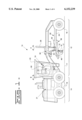
FIG. 1 is a side view of a motor grader;
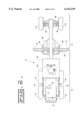
FIG. 2 is a top view of the motor grader;
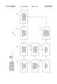
FIG. 3 is a schematic block diagram of an electro-hydraulic control system for the motor grader; and
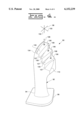
FIG. 4 is a side perspective of an electronic hand control designed in accordance with the present invention.
Referring to the Figures, wherein like numerals indicate like or corresponding parts throughout the several views, a motor grader is shown generally at 10 in FIGS. 1 and 2. The motor grader 10 is used primarily as a finishing tool to sculpt a surface of earth 11 to a final arrangement. Rather than moving large quantities of earth in the direction of travel like other machines, such as a bulldozer, the motor grader 10 move relatively small quantities of earth from side to side.
The motor grader 10 includes a front frame 12, a rear frame 14, and a blade 16 having a top 15 and a cutting edge 17. The front and rear frames 12 and 14 are supported by front tires 18 and rear tires 19. An operator cab 20 containing the many controls including a steering wheel 80 and a plurality of electronic hand controls 90 (see FIG. 4) necessary to operate the motor grader 10 is mounted on the front frame 12. An engine, shown generally at 21, is used to drive or power the motor grader 10. The engine 21 is mounted on the rear frame 14. A standard transmission (not shown) enables the engine 21 to drive the motor grader 10 in a forward or a backward direction as is known in the art. The transmission includes a plurality of forward and reverse gears permitting the transmission to operate in a forward position, a neutral position, and a reverse position. Such tranmissions are known in the art. Thus, the transmission permits motor grader 10 to operate in a plurality of forward or reverse gears. The gears as well as the direction of travel can be selected using an electronic hand control 90 as described below.
The blade 16, sometimes referred to as a moldboard, is used to move earth. The blade 16 is mounted on a linkage assembly shown generally at 22. The linkage assembly 22 allows the blade 16 to be moved to a variety of different positions with respect to the motor grader 10. Starting at the front of the motor grader 10 and working rearward toward the blade 16, the linkage assembly 22 includes a drawbar 24.
The drawbar 24 is mounted to the front frame 12 with a ball joint. The position of the drawbar 24 is controlled by three hydraulic cylinders, commonly referred to as a right lift cylinder 28, a left lift cylinder 30, and a center shift cylinder 32. A coupling, shown generally at 34, connects the three cylinders 28, 30, and 32 to the front frame 12. The coupling 34 can be moved during blade repositioning but is fixed stationary during earthmoving operations. The height of the blade 16 with respect to the surface of earth 11 below the motor grader 10, commonly referred to as the blade height, is controlled primarily with the right lift cylinder 28 and the left lift cylinder 30. Each lift cylinder, 28 and 30, functions to raise and lower the associated end of the blade 16. Thus, the right lift cylinder 28 raises and lowers the right end of blade 16. The center shift cylinder 32 moves the drawbar 24 from side to side relative to the front frame 12.
The drawbar 24 includes a large, flat plate commonly referred to as a yoke plate 36, as shown in FIG. 2. Beneath the yoke plate 36 is a large gear, commonly referred to as a circle 38. The circle 38 is rotated by a hydraulic motor commonly referred to as a circle drive 40, as shown in FIG. 1. Rotation of the circle 38 by the circle drive 40 pivots the blade 16 about an axis A fixed to the drawbar 24. The blade 16 is mounted to a hinge (not shown) on the circle 38 with a bracket (not shown). A hydraulic blade tip cylinder 46 is used to pitch the bracket forward or rearward and thus pitch the top 15 of the blade 16 forward and rearward relative to the cutting edge 17. The blade 16 is mounted to a sliding joint in the bracket allowing the blade 16 to be slid or shifted from side to side with respect to the bracket. A hydraulic side shift cylinder 50, shown in FIG. 2, is used to control the side to side shift of the blade 16.
Referring now to FIG. 2, a right articulation cylinder, shown generally at 52, is mounted to the right side of the rear frame 14 and a left articulation cylinder, shown generally at 54, is mounted to the left side of the rear frame 14. The right and left articulation cylinders 52 and 54 are hydraulic and used to rotate the front frame 12 about an axis B shown in FIG. 1. The axis B is commonly referred to as the articulation axis. In FIG. 2, the motor grader 10 is positioned in a neutral or zero articulation angles. The rear tires 19 are driven by a differential (not shown) as is well known in the art.
Adjacent the front tires 18 are a hydraulic right steering cylinder 82 and a hydraulic left steering cylinder 84. The right steering cylinder 82 and the left steering cylinder 84 are used to control the rotation of front tires 18 and thus steer motor grader 10. In a conventional motor grader 10 rotation of the steering wheel 80 is used to actuate the right steering cylinder 82 and the left steering cylinder 84. In the present invention, electronic hand controls 90 acting through an electro-hydraulic control system 60 can also control steering as more fully described below.
A hydraulic wheel lean cylinder 86 adjusts a wheel lean angle of front tires 18. Wheel lean cylinder 86 adjusts the wheel lean of the right and left front tires 18 in synchrony. Wheel lean angle refers to the angle between a front tire 18 and a line extending perpendicularly upward from a flat surface of the earth 11. Wheel lean angle is used by operators to stabilize the motor grader 10 during turns, to enable sharper turns of motor grader 10, and to help counteract the side forces generated by the blade 16 scraping the surface of the earth 11. Generally, the front tires 18 are leaned in the direction that the blade 16 is casting the moved earth. A four-bar linkage, known in the art, permits the wheel lean of both front tires 18 to be controlled by a single wheel lean cylinder 86.
FIG. 3 is a schematic block diagram of an electro-hydraulic control system 60 for the motor grader 10. The control system 60 is designed to operate the various hydraulic controls of the motor grader 10 described above. The system 60 includes a plurality of electronic hand controls 90 (see FIG. 4) represented by block 62, which transform the actions of an operator's hands on the hand controls 90 into a plurality of electrical input signals. These input signals carry operational information to an electronic control computer, represented by block 64.
The control computer 64 receives the electrical input signals produced by the hand controls 62, processes the operational information carried by the input signals, and transmits control signals to a plurality of drive solenoids, each of which is located in an electro-hydraulic actuator, represented by block 66.
The hydraulic portion of the control system 60 requires both high hydraulic pressure and low pilot pressure. High hydraulic pressure is provided by a hydraulic pump, represented by block 68. The hydraulic pump 68 receives a rotary motion, typically from the engine 21 of the motor grader 10, and produces high hydraulic pressure. Low pilot pressure is provided by a hydraulic pressure-reducing valve, represented by block 70. The hydraulic pressure-reducing valve 70 receives high hydraulic pressure from the hydraulic pump 68 and supplies low pilot pressure to the electro-hydraulic actuators 66.
Each electro-hydraulic actuator 66 includes an electrical drive solenoid and a hydraulic valve. The solenoid receives control signals from the electronic control computer 64 and produces a controlled mechanical movement of a core stem of the actuator 66. The hydraulic valve receives both the controlled mechanical movement of the core stem of the actuator 66 and low pilot pressure from the hydraulic pressure reducing valve 70 and produces controlled pilot hydraulic pressure for hydraulic valves, represented by block 72.
The hydraulic valves 72 receive both controlled pilot hydraulic pressure from the electro-hydraulic actuators 66 and high hydraulic pressure from the hydraulic pump 68 and produce controlled high hydraulic pressure for hydraulic actuators, cylinders, and motors, represented by block 74.
The hydraulic actuators, cylinders, and motors 74 receive controlled high hydraulic pressure from the hydraulic valves 72 and produce mechanical force to move the front frame 12 of the grader 10 and several mechanical linkages, represented by block 76. As described above, movement of the front frame 12 of the grader 10 with respect to the rear frame 14 of the grader 10 establishes the articulation angle. Movement of the mechanical linkages 76 establishes the position of the blade 16 or other implements.
Each hydraulic actuator, cylinder, and motor 74, such as the lift cylinders 28 and 30 and the circle drive motor 40, includes an electronic position sensor, represented by block 78. The electronic position sensors 78 transmit information regarding the position of its respective hydraulic actuator, cylinder, or motor 76 to the electronic control computer 64. In this manner, the control computer 64 can, for example, determine the articulation angle of the grader 10 and position the blade 16. With such information, the control computer 64 can perform additional operations.
In FIG. 4 an electronic hand control is generally shown at 90. Hand control 90 comprises a joystick 92. Joystick 92 includes a first end 94 mounted to a base 96. Joystick 92 is movable along a first axis 98 and a second axis 100, which is generally perpendicular to the first axis 98. Joystick 92 is rotatable about a third axis 102 that is perpendicular to both first axis 98 and second axis 100. In this specification and the accompanying claims the phrase movable on an axis encompasses both linear movement of joystick 92 on either the first axis 98 or the second axis 100 and rotation of joystick 92 about third axis 102. Joystick 92 is also moveable along axes between the first axis 98 and the second axis 100.
Joystick 92 includes a second end 104 opposite first end 94. Second end 104 includes a series of ledges 106 each of which is separated from the others by a riser 107. Preferably, the ledges 106 and risers 107 form a miniature staircase structure as shown in FIG. 4. A switch 108 is mounted on each ledge 106. Each ledge 106 preferably includes a textured pad 109. Second end 104 also includes a finger rest 110 separated from one of ledges 106 by a riser 107. As would be understood by one of ordinary skill, finger rest 110 may also include a switch 108. The ledges 106 and risers 107 form convenient locators for the operator's fingers allowing rapid non-visual location. They also provide an ergonomically comfortable location for the operator's fingers.
Switches 108 may comprise momentary or toggle switches or rocker switches depending on their function. Switches 108 are moveable along first axis 98, second axis 100 or both first axis 98 and second axis 100 depending on their construction. Movement of switches 108 on either first axis 98 or second axis 100 transmits a plurality of electronic input signals to electronic control computer 64. Electronic control computer 64 transmits an output signal in response to each input signal to one of the electro-hydraulic actuators 66 to cause actuation of a hydraulic valve 72 for control of mechanical linkages 76.
By way of example, one of switches 108 comprises a momentary toggle switch moveable along first axis 98. Movement of switch 108 in a first direction on first axis 98 transmits an electronic input signal to electronic control computer 64. Electronic control computer 64 transmits a first control signal to one of the electro-hydraulic actuators 66 to cause transmission to shift up to a higher gear. Movement of switch 108 in a second direction, opposite first direction, on first axis 98 causes the transmission to shift down to a lower gear.
By way of example, one of switches 108 controls wheel lean cylinder 86 through electro-hydraulic control system 60. Movement of switch 108 in a first direction along second axis 100 increases the wheel lean angle of front tires 18 as long as switch 108 is moved in the first direction. Movement of switch 108 in a second direction, opposite first direction, on second axis 100 decreases wheel lean angle as long as switch 108 is moved in the second direction.
By way of example, one of switches 108 comprises a three-position switch that controls the direction of travel of motor grader 10 through electro-hydraulic control system 60. Movement of switch 108 to a first position sends an electrical input signal to electronic control computer 64, which sends a first control signal to an electro-hydraulic actuator 66 to shift transmission into a forward direction or position. Movement of switch 108 to a second position sends a second control signal and shifts transmission into the neutral position. Movement of switch 108 to a third position sends a third control signal and shifts transmission to a reverse position.
As described above, joystick 92 is movable along the first axis 98, the second axis 100, or the third axis 102. Movement of joystick 92 along any of the axes transmits electrical input signals to the electronic control computer 64. The electronic control computer 64 then transmits a control signal to at least one of the electro-hydraulic actuators 66 in response to each input signal. As described above, actuating one of the electro-hydraulic actuators 66 actuates either a hydraulic cylinder, a hydraulic motor, or a hydraulic actuator 74.
By way of example, movement of joystick 92 in a first direction on first axis 98 sends an electronic input signal to electronic control computer 64 to actuate either the left lift cylinder 30 or the right lift cylinder 28. Thus, movement of joystick in a first direction on axis 98 lowers the left or right side of blade 16, and movement of joystick 92 in a second direction on first axis 98 raises the left or right side of blade 16. By way of example, movement of joystick 92 along axis 100 may be used to control actuation of the right steering cylinder 92 and the left steering cylinder 94. Thus, movement of joystick 92 in a first direction along second axis 100 rotates front wheels 18 in a first direction while movement of joystick 92 in a second direction on axis 100 rotates front wheels 18 in a second direction opposite the first direction. Thus, movement of joystick 92 on axis 100 can be used to control steering of motor grader 10. By way of example, rotation of joystick 92 about third axis 102 may be used to actuate circle drive 40, and thereby control the articulation angle of blade 16.
The present invention relates generally to an ergonomic electronic hand control 90 that can be used to control a plurality of functions of a motor grader 10 through an electro-hydraulic control system 60. Electronic hand control 90 includes a joystick 92 having a first end 94 and a second end 104. Joystick 92 is moveable along a plurality of axes and movement of joystick 92 on any of the axes generates electrical input signals that are used by the electro-hydraulic control system 60 to control a plurality of functions of motor grader 10. Second end 104 of joystick 92 includes a series of ledges 106 each of which is separated from each other by a riser 107. A switch 108 is mounted on each of ledges 106. Second end 104 preferably also includes a finger rest 110. Movement of switches 108 along one of a plurality of axes generates electrical input signals that are used by the electro-hydraulic control system 60 to control any of a plurality of motor grader 10 functions. Thus, the present invention provides an ergonomic electronic hand control 90 that permits an operator to properly position a hand on the hand control 90 without requiring the operator to look at the hand control 90.
The present invention has been described in accordance with the relevant legal standards, thus the foregoing description is exemplary rather than limiting in nature. Variations and modifications to the disclosed embodiment may become apparent to those skilled in the art and do come within the scope of this invention. Accordingly, the scope of legal protection afforded this invention can only be determined by studying the following claims.
Claims (8)
1. A hand control for a motor grader comprising:
an electro-hydraulic control system having an electronic control computer connected to a plurality of electro-hydraulic actuators, each of said plurality of electro-hydraulic actuators connected to at least one of a plurality of hydraulic valves and each of said plurality of hydraulic valves connected to one of a hydraulic actuator, a hydraulic cylinder, or a hydraulic motor;
a joystick having a first end opposite a second end and moveable on a plurality of axes;
said second end comprising a plurality of ledges each separated from each other by a riser; and
each of said ledges including a switch movable on at least one of said plurality of axes, movement of each of said switches on said axes transmitting a plurality of electrical input signals to said electronic control computer, said electronic control computer transmitting a control signal to one of said plurality of electro-hydraulic actuators in response to each of said electrical input signals.
2. A hand control for a motor grader as recited in claim 1 wherein said second end further comprises a finger rest, said finger rest adjacent one of said plurality of ledges and separated from said ledge by a riser.
3. A hand control for a motor grader as recited in claim 1 further comprising a transmission having a plurality of gears, said transmission connected to one of said electro-hydraulic actuators and wherein movement of one of said switches in a first direction on one of said axes transmits a first control signal to said electro-hydraulic actuator connected to said transmission;
said transmission shifting up at least one gear in response to said first control signal; and
movement of said switch in a second direction opposite said first direction on said axis transmitting a second control signal to said electro-hydraulic actuator connected to said transmission, said transmission shifting down at least one gear in response to said second control signal.
4. A hand control for a motor grader as recited in claim 1 further comprising a wheel lean cylinder connected to a pair of front tires, said wheel lean cylinder connected to one of said electro-hydraulic actuators and wherein movement of one of said switches in a first direction on one of said axes transmits a first control signal to said electro-hydraulic actuator connected to said wheel lean cylinder, said wheel lean cylinder increasing a lean angle of said front tires in response to said first control signal; and
movement of said switch in a second direction opposite said first direction on said axis transmitting a second control signal to said electro-hydraulic actuator connected to said wheel lean cylinder, said wheel lean cylinder decreasing said lean angle of said front tires in response to said second control signal.
5. A hand control for a motor grader as recited in claim 1 further comprising a transmission having a neutral position, a forward position, and a reverse position, said transmission connected to one of said electro-hydraulic actuators and wherein one of said switches is movable between three positions;
movement of said switch to a first position transmitting a first control signal to said electro-hydraulic actuator connected to said transmission, said transmission shifting to said forward position in response to said first control signal;
movement of said switch to a second position transmitting a second control signal to said electro-hydraulic actuator connected to said transmission, said transmission shifting to said neutral position in response to said second control signal; and
movement of said switch to a third position transmitting a third control signal to said electro-hydraulic actuator connected to said transmission, said transmission shifting to said reverse position in response to said third control signal.
6. A hand control for a motor grader as recited in claim 1 wherein movement of said joystick on said plurality of axes sends a plurality of electrical input signals to said electronic control computer, said electronic control computer transmitting a control signal to one of said plurality of electro-hydraulic actuators in response to each of said electrical input signals.
7. A hand control for a motor grader as recited in claim 6 further comprising a right steering cylinder and a left steering cylinder, said right and left steering cylinders each connected to a front tire and to at least one electro-hydraulic actuator wherein movement of said joystick in a first direction on one of said axes transmits a first control signal to said electro-hydraulic actuators connected to said right and left steering cylinders, said right and left steering cylinders rotating said front tires in a first direction in response to said first control signal; and
movement of said joystick in a second direction opposite said first direction on said axis transmitting a second control signal to said electro-hydraulic actuators connected to said right and left steering cylinders, said right and left steering cylinders rotating said front tires in a second direction opposite said first direction in response to said second control signal.
8. A hand control for a motor grader as recited in claim 6 further comprising one of a right lift cylinder and a left lift cylinder, said right lift cylinder or said left lift cylinder connected to a blade and to at least one electro-hydraulic actuator wherein movement of said joystick in a first direction on one of said axes transmits a first control signal to said electro-hydraulic actuator connected to said right or left lift cylinder, said right or left lift cylinder raising said blade in response to said first control signal; and
movement of said joystick in a second direction opposite said first direction on said axis transmitting a second control signal to said electro-hydraulic actuator connected to said right or left lift cylinder, said right or left lift cylinder lowering said blade in response to said second control signal.
Priority Applications (3)
| Application Number | Priority Date | Filing Date | Title |
|---|---|---|---|
| US09/237,166 US6152239A (en) | 1999-01-25 | 1999-01-25 | Ergonomic electronic hand control for a motor grader |
| DE19961532A DE19961532A1 (en) | 1999-01-25 | 1999-12-20 | Ergonomically optimised joystick input device for control of functions on a hydraulic earth moving machine |
| CA002293991A CA2293991A1 (en) | 1999-01-25 | 2000-01-07 | Ergonomic hand control for a motor grader |
Applications Claiming Priority (1)
| Application Number | Priority Date | Filing Date | Title |
|---|---|---|---|
| US09/237,166 US6152239A (en) | 1999-01-25 | 1999-01-25 | Ergonomic electronic hand control for a motor grader |
Publications (1)
| Publication Number | Publication Date |
|---|---|
| US6152239A true US6152239A (en) | 2000-11-28 |
Family
ID=22892597
Family Applications (1)
| Application Number | Title | Priority Date | Filing Date |
|---|---|---|---|
| US09/237,166 Expired - Lifetime US6152239A (en) | 1999-01-25 | 1999-01-25 | Ergonomic electronic hand control for a motor grader |
Country Status (3)
| Country | Link |
|---|---|
| US (1) | US6152239A (en) |
| CA (1) | CA2293991A1 (en) |
| DE (1) | DE19961532A1 (en) |
Cited By (35)
| Publication number | Priority date | Publication date | Assignee | Title |
|---|---|---|---|---|
| WO2002088865A1 (en) * | 2001-04-26 | 2002-11-07 | Jlg Industries, Inc. | Split grip control lever for heavy machinery |
| WO2002090668A1 (en) * | 2001-05-04 | 2002-11-14 | Volvo Motor Graders Limited | Joystick arrangement for motor graders |
| US20020178624A1 (en) * | 2001-06-01 | 2002-12-05 | Ryo Yamamoto | Joystick device |
| US20030112219A1 (en) * | 2001-12-14 | 2003-06-19 | Imed Gharsalli | Input/output interface control |
| US20050279561A1 (en) * | 2004-06-22 | 2005-12-22 | Caterpillar Inc. | Work machine joystick control system |
| US20060016634A1 (en) * | 2004-07-22 | 2006-01-26 | Cnh America Llc | Handle-style loading control panel for bale wagons |
| US20060021770A1 (en) * | 2004-07-28 | 2006-02-02 | Caterpillar Inc. | Rear-mounted work implement control system |
| US20060118313A1 (en) * | 2004-12-08 | 2006-06-08 | Nicholas James A | Surface-contouring implement |
| US20060137931A1 (en) * | 2004-12-23 | 2006-06-29 | Caterpillar Inc. | Steering system with joystick mounted controls |
| US20080083141A1 (en) * | 2006-05-15 | 2008-04-10 | Paul Treuthardt | Electronic control device |
| US7409879B2 (en) * | 2004-11-25 | 2008-08-12 | Liebher-Hydraulikbagger Gmbh | Construction machine comprising a joystick control |
| US20090223736A1 (en) * | 2008-03-07 | 2009-09-10 | Deere And Company | Input control pattern |
| US20090229149A1 (en) * | 2008-03-12 | 2009-09-17 | Tesinsky Vincent E | Remote control for shifting the gears of a snowplow truck transmission |
| US20110035109A1 (en) * | 2009-08-05 | 2011-02-10 | Caterpillar Inc. | Steering system with automated articulation control |
| US20110088961A1 (en) * | 2009-10-19 | 2011-04-21 | Cnh America Llc | Electronic throttle on control handle |
| US20120160526A1 (en) * | 2010-12-22 | 2012-06-28 | Caterpillar Inc. | System and method for controlling a rotation angle of a motor grader blade |
| EP1650359A3 (en) * | 2004-10-21 | 2013-02-13 | Deere & Company | Multiple mode operational system for work vehicle braking or propulsion |
| US8700271B2 (en) * | 2012-02-07 | 2014-04-15 | Caterpillar Inc. | Machine with four degrees of freedom implement control joystick and track type tractor using same |
| US9086130B1 (en) | 2014-04-21 | 2015-07-21 | Caterpillar Inc. | Transmission and hoist control arrangement |
| USD735100S1 (en) | 2014-04-21 | 2015-07-28 | Caterpillar Inc. | Transmission shifter |
| USD736719S1 (en) * | 2013-07-24 | 2015-08-18 | J. Schmalz Gmbh | Control element |
| US9217238B2 (en) | 2014-03-17 | 2015-12-22 | Caterpillar Inc. | Automatic articulation machine states |
| US9234330B2 (en) | 2014-03-17 | 2016-01-12 | Caterpillar Inc. | Automatic articulation behavior during error and high speed conditions |
| EP2980317A1 (en) * | 2014-07-30 | 2016-02-03 | Caterpillar Inc. | Multiple control patterns for hydraulically operated machines with hand and foot controls |
| US9290910B2 (en) | 2014-03-17 | 2016-03-22 | Caterpillar Inc. | Automatic articulation failure mode protection |
| US9428884B2 (en) | 2014-03-17 | 2016-08-30 | Caterpillar Inc. | Articulation covering complete range of steering angles in automatic articulation feature |
| US9637889B2 (en) | 2015-06-12 | 2017-05-02 | Cnh Industrial America Llc | Automated moldboard draft control system and method |
| CN106609530A (en) * | 2015-10-22 | 2017-05-03 | 迪尔公司 | Distributed operator control equipment for work vehicles |
| US10036139B2 (en) * | 2014-11-24 | 2018-07-31 | Caterpillar Inc. | Machine input device having multi-axis tool control |
| US10378176B2 (en) * | 2015-11-25 | 2019-08-13 | Johnnie Leroy Mason | Joystick controlled scraper blade assembly |
| US10975547B2 (en) | 2018-12-07 | 2021-04-13 | Deere & Company | Two-dimensional attachment grade control for work vehicle |
| US10988913B2 (en) | 2019-02-21 | 2021-04-27 | Deere & Company | Blade for work vehicle |
| US11124941B2 (en) * | 2018-03-29 | 2021-09-21 | Cnh Industrial America Llc | Motor grader with comfort steering |
| US11286641B2 (en) * | 2018-12-07 | 2022-03-29 | Deere & Company | Attachment-configurable system for a work machine |
| US20220136203A1 (en) * | 2020-10-30 | 2022-05-05 | Caterpillar Inc. | Coordinated actuator control by an operator control |
Families Citing this family (2)
| Publication number | Priority date | Publication date | Assignee | Title |
|---|---|---|---|---|
| WO2009050745A1 (en) * | 2007-10-17 | 2009-04-23 | Komatsu Utility Europe S.P.A. | Control device for earth moving machines |
| DE102015113440A1 (en) | 2015-08-14 | 2017-02-16 | David Weldin | Control lever for an input device for controlling an actuator, input device and method for operating an input device |
Citations (11)
| Publication number | Priority date | Publication date | Assignee | Title |
|---|---|---|---|---|
| US4012014A (en) * | 1975-09-11 | 1977-03-15 | Mcdonnell Douglas Corporation | Aircraft flight controller |
| US4350055A (en) * | 1979-05-29 | 1982-09-21 | Pinomaeki Sakari | Lever operated control apparatus |
| US4641723A (en) * | 1982-06-23 | 1987-02-10 | Honda Giken Kogyo Kabushiki Kaisha | Handle switch assembly for a motor vehicle |
| US4738417A (en) * | 1987-02-02 | 1988-04-19 | Fmc Corporation | Hand operated control |
| US4795296A (en) * | 1986-11-17 | 1989-01-03 | California Institute Of Technology | Hand-held robot end effector controller having movement and force control |
| US4811921A (en) * | 1987-06-22 | 1989-03-14 | Whitaker Charles N | Cyclic control stick |
| US4952919A (en) * | 1989-04-06 | 1990-08-28 | Tektronix, Inc. | Trackball mechanism |
| US5503040A (en) * | 1993-11-12 | 1996-04-02 | Binagraphics, Inc. | Computer interface device |
| US5566586A (en) * | 1992-02-13 | 1996-10-22 | Zf Friedrichshafen Ab | Steering stick for switching or actuating components of a utility vehicle |
| US5591082A (en) * | 1995-01-05 | 1997-01-07 | Thrustmaster, Inc. | Side-mounted throttle and weapons controller for computer video games and flight simulation |
| US5768974A (en) * | 1995-03-22 | 1998-06-23 | Kabushiki Kaisha Toyoda Jidoshokki Seisakusho | Swash plate type compressor |
-
1999
- 1999-01-25 US US09/237,166 patent/US6152239A/en not_active Expired - Lifetime
- 1999-12-20 DE DE19961532A patent/DE19961532A1/en not_active Withdrawn
-
2000
- 2000-01-07 CA CA002293991A patent/CA2293991A1/en not_active Abandoned
Patent Citations (11)
| Publication number | Priority date | Publication date | Assignee | Title |
|---|---|---|---|---|
| US4012014A (en) * | 1975-09-11 | 1977-03-15 | Mcdonnell Douglas Corporation | Aircraft flight controller |
| US4350055A (en) * | 1979-05-29 | 1982-09-21 | Pinomaeki Sakari | Lever operated control apparatus |
| US4641723A (en) * | 1982-06-23 | 1987-02-10 | Honda Giken Kogyo Kabushiki Kaisha | Handle switch assembly for a motor vehicle |
| US4795296A (en) * | 1986-11-17 | 1989-01-03 | California Institute Of Technology | Hand-held robot end effector controller having movement and force control |
| US4738417A (en) * | 1987-02-02 | 1988-04-19 | Fmc Corporation | Hand operated control |
| US4811921A (en) * | 1987-06-22 | 1989-03-14 | Whitaker Charles N | Cyclic control stick |
| US4952919A (en) * | 1989-04-06 | 1990-08-28 | Tektronix, Inc. | Trackball mechanism |
| US5566586A (en) * | 1992-02-13 | 1996-10-22 | Zf Friedrichshafen Ab | Steering stick for switching or actuating components of a utility vehicle |
| US5503040A (en) * | 1993-11-12 | 1996-04-02 | Binagraphics, Inc. | Computer interface device |
| US5591082A (en) * | 1995-01-05 | 1997-01-07 | Thrustmaster, Inc. | Side-mounted throttle and weapons controller for computer video games and flight simulation |
| US5768974A (en) * | 1995-03-22 | 1998-06-23 | Kabushiki Kaisha Toyoda Jidoshokki Seisakusho | Swash plate type compressor |
Cited By (55)
| Publication number | Priority date | Publication date | Assignee | Title |
|---|---|---|---|---|
| WO2002088865A1 (en) * | 2001-04-26 | 2002-11-07 | Jlg Industries, Inc. | Split grip control lever for heavy machinery |
| WO2002090668A1 (en) * | 2001-05-04 | 2002-11-14 | Volvo Motor Graders Limited | Joystick arrangement for motor graders |
| US20020178624A1 (en) * | 2001-06-01 | 2002-12-05 | Ryo Yamamoto | Joystick device |
| US6892481B2 (en) * | 2001-06-01 | 2005-05-17 | Kawasaki Jukogyo Kabushiki Kaisha | Joystick device |
| US20030112219A1 (en) * | 2001-12-14 | 2003-06-19 | Imed Gharsalli | Input/output interface control |
| US7497298B2 (en) | 2004-06-22 | 2009-03-03 | Caterpillar Inc. | Machine joystick control system |
| US20050279561A1 (en) * | 2004-06-22 | 2005-12-22 | Caterpillar Inc. | Work machine joystick control system |
| US20060016634A1 (en) * | 2004-07-22 | 2006-01-26 | Cnh America Llc | Handle-style loading control panel for bale wagons |
| US20060021770A1 (en) * | 2004-07-28 | 2006-02-02 | Caterpillar Inc. | Rear-mounted work implement control system |
| US8069927B2 (en) * | 2004-07-28 | 2011-12-06 | Caterpillar Inc. | Rear-mounted work implement control system |
| EP1650359A3 (en) * | 2004-10-21 | 2013-02-13 | Deere & Company | Multiple mode operational system for work vehicle braking or propulsion |
| US7409879B2 (en) * | 2004-11-25 | 2008-08-12 | Liebher-Hydraulikbagger Gmbh | Construction machine comprising a joystick control |
| US20060118313A1 (en) * | 2004-12-08 | 2006-06-08 | Nicholas James A | Surface-contouring implement |
| US7334658B2 (en) * | 2004-12-23 | 2008-02-26 | Caterpillar Inc. | Steering system with joystick mounted controls |
| US20060137931A1 (en) * | 2004-12-23 | 2006-06-29 | Caterpillar Inc. | Steering system with joystick mounted controls |
| US7681340B2 (en) * | 2006-05-15 | 2010-03-23 | Monroe Truck Equipment, Inc. | Electronic control device |
| US20080083141A1 (en) * | 2006-05-15 | 2008-04-10 | Paul Treuthardt | Electronic control device |
| US8091678B2 (en) | 2008-03-07 | 2012-01-10 | Deere & Company | Input control pattern |
| US20090223733A1 (en) * | 2008-03-07 | 2009-09-10 | Deere And Company | Auxiliary input arrangement |
| US20090223092A1 (en) * | 2008-03-07 | 2009-09-10 | Deere And Company | Arrangement of steering wheel and operator seat assembly |
| US20090223735A1 (en) * | 2008-03-07 | 2009-09-10 | Deere And Company | Joystick configuration |
| US8424632B2 (en) | 2008-03-07 | 2013-04-23 | Deere & Company | Input control pattern |
| US7857090B2 (en) | 2008-03-07 | 2010-12-28 | Deere & Company | Auxiliary input arrangement |
| US20090223736A1 (en) * | 2008-03-07 | 2009-09-10 | Deere And Company | Input control pattern |
| US7913798B2 (en) | 2008-03-07 | 2011-03-29 | Deere & Company | Armrest mounted grader control |
| US8360193B2 (en) | 2008-03-07 | 2013-01-29 | Deere & Company | Arrangement of steering wheel and operator seat assembly |
| US8146704B2 (en) | 2008-03-07 | 2012-04-03 | Deere & Company | Joystick configuration |
| US20090223734A1 (en) * | 2008-03-07 | 2009-09-10 | Deere And Company | Armrest mounted grader control |
| US8104566B2 (en) | 2008-03-07 | 2012-01-31 | Deere & Company | Arrangement of steering wheel and operator seat assembly |
| US7798278B2 (en) * | 2008-03-12 | 2010-09-21 | Tesinsky Vincent E | Remote control for shifting the gears of a snowplow truck transmission |
| US20090229149A1 (en) * | 2008-03-12 | 2009-09-17 | Tesinsky Vincent E | Remote control for shifting the gears of a snowplow truck transmission |
| US20110035109A1 (en) * | 2009-08-05 | 2011-02-10 | Caterpillar Inc. | Steering system with automated articulation control |
| US8548680B2 (en) * | 2009-08-05 | 2013-10-01 | Caterpillar Inc. | Steering system with automated articulation control |
| US8100218B2 (en) | 2009-10-19 | 2012-01-24 | Cnh America Llc | Electronic throttle on control handle |
| US20110088961A1 (en) * | 2009-10-19 | 2011-04-21 | Cnh America Llc | Electronic throttle on control handle |
| US8985233B2 (en) * | 2010-12-22 | 2015-03-24 | Caterpillar Inc. | System and method for controlling a rotation angle of a motor grader blade |
| US20120160526A1 (en) * | 2010-12-22 | 2012-06-28 | Caterpillar Inc. | System and method for controlling a rotation angle of a motor grader blade |
| US8700271B2 (en) * | 2012-02-07 | 2014-04-15 | Caterpillar Inc. | Machine with four degrees of freedom implement control joystick and track type tractor using same |
| USD736719S1 (en) * | 2013-07-24 | 2015-08-18 | J. Schmalz Gmbh | Control element |
| US9217238B2 (en) | 2014-03-17 | 2015-12-22 | Caterpillar Inc. | Automatic articulation machine states |
| US9234330B2 (en) | 2014-03-17 | 2016-01-12 | Caterpillar Inc. | Automatic articulation behavior during error and high speed conditions |
| US9290910B2 (en) | 2014-03-17 | 2016-03-22 | Caterpillar Inc. | Automatic articulation failure mode protection |
| US9428884B2 (en) | 2014-03-17 | 2016-08-30 | Caterpillar Inc. | Articulation covering complete range of steering angles in automatic articulation feature |
| USD735100S1 (en) | 2014-04-21 | 2015-07-28 | Caterpillar Inc. | Transmission shifter |
| US9086130B1 (en) | 2014-04-21 | 2015-07-21 | Caterpillar Inc. | Transmission and hoist control arrangement |
| EP2980317A1 (en) * | 2014-07-30 | 2016-02-03 | Caterpillar Inc. | Multiple control patterns for hydraulically operated machines with hand and foot controls |
| US10036139B2 (en) * | 2014-11-24 | 2018-07-31 | Caterpillar Inc. | Machine input device having multi-axis tool control |
| US9637889B2 (en) | 2015-06-12 | 2017-05-02 | Cnh Industrial America Llc | Automated moldboard draft control system and method |
| CN106609530A (en) * | 2015-10-22 | 2017-05-03 | 迪尔公司 | Distributed operator control equipment for work vehicles |
| US10378176B2 (en) * | 2015-11-25 | 2019-08-13 | Johnnie Leroy Mason | Joystick controlled scraper blade assembly |
| US11124941B2 (en) * | 2018-03-29 | 2021-09-21 | Cnh Industrial America Llc | Motor grader with comfort steering |
| US10975547B2 (en) | 2018-12-07 | 2021-04-13 | Deere & Company | Two-dimensional attachment grade control for work vehicle |
| US11286641B2 (en) * | 2018-12-07 | 2022-03-29 | Deere & Company | Attachment-configurable system for a work machine |
| US10988913B2 (en) | 2019-02-21 | 2021-04-27 | Deere & Company | Blade for work vehicle |
| US20220136203A1 (en) * | 2020-10-30 | 2022-05-05 | Caterpillar Inc. | Coordinated actuator control by an operator control |
Also Published As
| Publication number | Publication date |
|---|---|
| DE19961532A1 (en) | 2000-07-27 |
| CA2293991A1 (en) | 2000-07-25 |
Similar Documents
| Publication | Publication Date | Title |
|---|---|---|
| US6152239A (en) | Ergonomic electronic hand control for a motor grader | |
| USH1822H (en) | Miniature joystick mounted on a joystick | |
| USH1831H (en) | Ergonomic motor grader vehicle control apparatus | |
| US6278955B1 (en) | Method for automatically positioning the blade of a motor grader to a memory position | |
| US6152237A (en) | Method for automatically controlling the articulation angle of a motor grader | |
| US20020166267A1 (en) | Advanced motor grader controls | |
| CN106609529B (en) | Operator control for a work vehicle | |
| CA2506301C (en) | Work machine joystick control system | |
| US9771705B2 (en) | Work vehicle operator control | |
| US8380402B2 (en) | Control systems and methods for heavy equipment | |
| US9797114B2 (en) | Work vehicle operator control with increment adjust | |
| CN106609530B (en) | Distributed operator control device for work vehicle | |
| EP1344115B1 (en) | Joystick steering on power machine with filtered steering input | |
| US6129156A (en) | Method for automatically moving the blade of a motor grader from a present blade position to a mirror image position | |
| CA2486037C (en) | Pattern selector valve for control levers of a work vehicle | |
| US6028524A (en) | Method for monitoring the position of a motor grader blade relative to a motor grader frame | |
| US20130180744A1 (en) | Operator Interface for an Implement Control System | |
| US4645030A (en) | Multi-function directional handle | |
| US11573591B2 (en) | Machine joystick with ergonomic features | |
| USH1851H (en) | Motor grader having dual steering mechanisms | |
| US6041673A (en) | Dual function throttle control system for heavy construction equipment machines | |
| CN111287232A (en) | Work implement attachment for a work machine | |
| CA2288572A1 (en) | Motor grader steerable by a joystick and a steering wheel | |
| US11614766B2 (en) | Machine joystick with comfort and accessibility features | |
| CN212160481U (en) | Control device for construction vehicle and construction vehicle |
Legal Events
| Date | Code | Title | Description |
|---|---|---|---|
| AS | Assignment |
Owner name: CATERPILLAR, INC., ILLINOIS Free format text: ASSIGNMENT OF ASSIGNORS INTEREST;ASSIGNORS:KELLEY, CRAIG B.;SHEARER, DANIEL E.;BOAST, SUSAN M.;REEL/FRAME:009732/0150;SIGNING DATES FROM 19990112 TO 19990114 |
|
| STCF | Information on status: patent grant |
Free format text: PATENTED CASE |
|
| FPAY | Fee payment |
Year of fee payment: 4 |
|
| FPAY | Fee payment |
Year of fee payment: 8 |
|
| FPAY | Fee payment |
Year of fee payment: 12 |