US6152335A - Aerosol spray texture apparatus for a particulate containing material - Google Patents
Aerosol spray texture apparatus for a particulate containing material Download PDFInfo
- Publication number
- US6152335A US6152335A US09/203,547 US20354798A US6152335A US 6152335 A US6152335 A US 6152335A US 20354798 A US20354798 A US 20354798A US 6152335 A US6152335 A US 6152335A
- Authority
- US
- United States
- Prior art keywords
- stem
- valve
- actuator
- assembly
- metering
- Prior art date
- Legal status (The legal status is an assumption and is not a legal conclusion. Google has not performed a legal analysis and makes no representation as to the accuracy of the status listed.)
- Expired - Lifetime
Links
Images


Classifications
-
- B—PERFORMING OPERATIONS; TRANSPORTING
- B05—SPRAYING OR ATOMISING IN GENERAL; APPLYING FLUENT MATERIALS TO SURFACES, IN GENERAL
- B05B—SPRAYING APPARATUS; ATOMISING APPARATUS; NOZZLES
- B05B1/00—Nozzles, spray heads or other outlets, with or without auxiliary devices such as valves, heating means
- B05B1/12—Nozzles, spray heads or other outlets, with or without auxiliary devices such as valves, heating means capable of producing different kinds of discharge, e.g. either jet or spray
-
- B—PERFORMING OPERATIONS; TRANSPORTING
- B05—SPRAYING OR ATOMISING IN GENERAL; APPLYING FLUENT MATERIALS TO SURFACES, IN GENERAL
- B05B—SPRAYING APPARATUS; ATOMISING APPARATUS; NOZZLES
- B05B1/00—Nozzles, spray heads or other outlets, with or without auxiliary devices such as valves, heating means
- B05B1/02—Nozzles, spray heads or other outlets, with or without auxiliary devices such as valves, heating means designed to produce a jet, spray, or other discharge of particular shape or nature, e.g. in single drops, or having an outlet of particular shape
- B05B1/04—Nozzles, spray heads or other outlets, with or without auxiliary devices such as valves, heating means designed to produce a jet, spray, or other discharge of particular shape or nature, e.g. in single drops, or having an outlet of particular shape in flat form, e.g. fan-like, sheet-like
-
- B—PERFORMING OPERATIONS; TRANSPORTING
- B05—SPRAYING OR ATOMISING IN GENERAL; APPLYING FLUENT MATERIALS TO SURFACES, IN GENERAL
- B05B—SPRAYING APPARATUS; ATOMISING APPARATUS; NOZZLES
- B05B1/00—Nozzles, spray heads or other outlets, with or without auxiliary devices such as valves, heating means
- B05B1/14—Nozzles, spray heads or other outlets, with or without auxiliary devices such as valves, heating means with multiple outlet openings; with strainers in or outside the outlet opening
- B05B1/16—Nozzles, spray heads or other outlets, with or without auxiliary devices such as valves, heating means with multiple outlet openings; with strainers in or outside the outlet opening having selectively- effective outlets
- B05B1/1627—Nozzles, spray heads or other outlets, with or without auxiliary devices such as valves, heating means with multiple outlet openings; with strainers in or outside the outlet opening having selectively- effective outlets with a selecting mechanism comprising a gate valve, a sliding valve or a cock
- B05B1/1636—Nozzles, spray heads or other outlets, with or without auxiliary devices such as valves, heating means with multiple outlet openings; with strainers in or outside the outlet opening having selectively- effective outlets with a selecting mechanism comprising a gate valve, a sliding valve or a cock by relative rotative movement of the valve elements
- B05B1/1645—Nozzles, spray heads or other outlets, with or without auxiliary devices such as valves, heating means with multiple outlet openings; with strainers in or outside the outlet opening having selectively- effective outlets with a selecting mechanism comprising a gate valve, a sliding valve or a cock by relative rotative movement of the valve elements the outlets being rotated during selection
- B05B1/1654—Nozzles, spray heads or other outlets, with or without auxiliary devices such as valves, heating means with multiple outlet openings; with strainers in or outside the outlet opening having selectively- effective outlets with a selecting mechanism comprising a gate valve, a sliding valve or a cock by relative rotative movement of the valve elements the outlets being rotated during selection about an axis parallel to the liquid passage in the stationary valve element
-
- B—PERFORMING OPERATIONS; TRANSPORTING
- B05—SPRAYING OR ATOMISING IN GENERAL; APPLYING FLUENT MATERIALS TO SURFACES, IN GENERAL
- B05B—SPRAYING APPARATUS; ATOMISING APPARATUS; NOZZLES
- B05B1/00—Nozzles, spray heads or other outlets, with or without auxiliary devices such as valves, heating means
- B05B1/26—Nozzles, spray heads or other outlets, with or without auxiliary devices such as valves, heating means with means for mechanically breaking-up or deflecting the jet after discharge, e.g. with fixed deflectors; Breaking-up the discharged liquid or other fluent material by impinging jets
-
- B—PERFORMING OPERATIONS; TRANSPORTING
- B05—SPRAYING OR ATOMISING IN GENERAL; APPLYING FLUENT MATERIALS TO SURFACES, IN GENERAL
- B05B—SPRAYING APPARATUS; ATOMISING APPARATUS; NOZZLES
- B05B1/00—Nozzles, spray heads or other outlets, with or without auxiliary devices such as valves, heating means
- B05B1/34—Nozzles, spray heads or other outlets, with or without auxiliary devices such as valves, heating means designed to influence the nature of flow of the liquid or other fluent material, e.g. to produce swirl
-
- B—PERFORMING OPERATIONS; TRANSPORTING
- B05—SPRAYING OR ATOMISING IN GENERAL; APPLYING FLUENT MATERIALS TO SURFACES, IN GENERAL
- B05B—SPRAYING APPARATUS; ATOMISING APPARATUS; NOZZLES
- B05B7/00—Spraying apparatus for discharge of liquids or other fluent materials from two or more sources, e.g. of liquid and air, of powder and gas
- B05B7/24—Spraying apparatus for discharge of liquids or other fluent materials from two or more sources, e.g. of liquid and air, of powder and gas with means, e.g. a container, for supplying liquid or other fluent material to a discharge device
- B05B7/2402—Apparatus to be carried on or by a person, e.g. by hand; Apparatus comprising containers fixed to the discharge device
- B05B7/2405—Apparatus to be carried on or by a person, e.g. by hand; Apparatus comprising containers fixed to the discharge device using an atomising fluid as carrying fluid for feeding, e.g. by suction or pressure, a carried liquid from the container to the nozzle
- B05B7/2435—Apparatus to be carried on or by a person, e.g. by hand; Apparatus comprising containers fixed to the discharge device using an atomising fluid as carrying fluid for feeding, e.g. by suction or pressure, a carried liquid from the container to the nozzle the carried liquid and the main stream of atomising fluid being brought together by parallel conduits placed one inside the other
-
- B—PERFORMING OPERATIONS; TRANSPORTING
- B05—SPRAYING OR ATOMISING IN GENERAL; APPLYING FLUENT MATERIALS TO SURFACES, IN GENERAL
- B05D—PROCESSES FOR APPLYING FLUENT MATERIALS TO SURFACES, IN GENERAL
- B05D1/00—Processes for applying liquids or other fluent materials
- B05D1/02—Processes for applying liquids or other fluent materials performed by spraying
-
- B—PERFORMING OPERATIONS; TRANSPORTING
- B05—SPRAYING OR ATOMISING IN GENERAL; APPLYING FLUENT MATERIALS TO SURFACES, IN GENERAL
- B05D—PROCESSES FOR APPLYING FLUENT MATERIALS TO SURFACES, IN GENERAL
- B05D5/00—Processes for applying liquids or other fluent materials to surfaces to obtain special surface effects, finishes or structures
- B05D5/06—Processes for applying liquids or other fluent materials to surfaces to obtain special surface effects, finishes or structures to obtain multicolour or other optical effects
- B05D5/061—Special surface effect
-
- B—PERFORMING OPERATIONS; TRANSPORTING
- B65—CONVEYING; PACKING; STORING; HANDLING THIN OR FILAMENTARY MATERIAL
- B65D—CONTAINERS FOR STORAGE OR TRANSPORT OF ARTICLES OR MATERIALS, e.g. BAGS, BARRELS, BOTTLES, BOXES, CANS, CARTONS, CRATES, DRUMS, JARS, TANKS, HOPPERS, FORWARDING CONTAINERS; ACCESSORIES, CLOSURES, OR FITTINGS THEREFOR; PACKAGING ELEMENTS; PACKAGES
- B65D83/00—Containers or packages with special means for dispensing contents
- B65D83/14—Containers or packages with special means for dispensing contents for delivery of liquid or semi-liquid contents by internal gaseous pressure, i.e. aerosol containers comprising propellant for a product delivered by a propellant
- B65D83/16—Containers or packages with special means for dispensing contents for delivery of liquid or semi-liquid contents by internal gaseous pressure, i.e. aerosol containers comprising propellant for a product delivered by a propellant characterised by the actuating means
- B65D83/20—Containers or packages with special means for dispensing contents for delivery of liquid or semi-liquid contents by internal gaseous pressure, i.e. aerosol containers comprising propellant for a product delivered by a propellant characterised by the actuating means operated by manual action, e.g. button-type actuator or actuator caps
- B65D83/201—Lever-operated actuators
-
- B—PERFORMING OPERATIONS; TRANSPORTING
- B65—CONVEYING; PACKING; STORING; HANDLING THIN OR FILAMENTARY MATERIAL
- B65D—CONTAINERS FOR STORAGE OR TRANSPORT OF ARTICLES OR MATERIALS, e.g. BAGS, BARRELS, BOTTLES, BOXES, CANS, CARTONS, CRATES, DRUMS, JARS, TANKS, HOPPERS, FORWARDING CONTAINERS; ACCESSORIES, CLOSURES, OR FITTINGS THEREFOR; PACKAGING ELEMENTS; PACKAGES
- B65D83/00—Containers or packages with special means for dispensing contents
- B65D83/14—Containers or packages with special means for dispensing contents for delivery of liquid or semi-liquid contents by internal gaseous pressure, i.e. aerosol containers comprising propellant for a product delivered by a propellant
- B65D83/16—Containers or packages with special means for dispensing contents for delivery of liquid or semi-liquid contents by internal gaseous pressure, i.e. aerosol containers comprising propellant for a product delivered by a propellant characterised by the actuating means
- B65D83/20—Containers or packages with special means for dispensing contents for delivery of liquid or semi-liquid contents by internal gaseous pressure, i.e. aerosol containers comprising propellant for a product delivered by a propellant characterised by the actuating means operated by manual action, e.g. button-type actuator or actuator caps
- B65D83/205—Actuator caps, or peripheral actuator skirts, attachable to the aerosol container
- B65D83/206—Actuator caps, or peripheral actuator skirts, attachable to the aerosol container comprising a cantilevered actuator element, e.g. a lever pivoting about a living hinge
-
- B—PERFORMING OPERATIONS; TRANSPORTING
- B65—CONVEYING; PACKING; STORING; HANDLING THIN OR FILAMENTARY MATERIAL
- B65D—CONTAINERS FOR STORAGE OR TRANSPORT OF ARTICLES OR MATERIALS, e.g. BAGS, BARRELS, BOTTLES, BOXES, CANS, CARTONS, CRATES, DRUMS, JARS, TANKS, HOPPERS, FORWARDING CONTAINERS; ACCESSORIES, CLOSURES, OR FITTINGS THEREFOR; PACKAGING ELEMENTS; PACKAGES
- B65D83/00—Containers or packages with special means for dispensing contents
- B65D83/14—Containers or packages with special means for dispensing contents for delivery of liquid or semi-liquid contents by internal gaseous pressure, i.e. aerosol containers comprising propellant for a product delivered by a propellant
- B65D83/28—Nozzles, nozzle fittings or accessories specially adapted therefor
- B65D83/30—Nozzles, nozzle fittings or accessories specially adapted therefor for guiding the flow of spray, e.g. funnels, hoods
- B65D83/303—Nozzles, nozzle fittings or accessories specially adapted therefor for guiding the flow of spray, e.g. funnels, hoods using extension tubes located in or at the outlet duct of the nozzle assembly
-
- B—PERFORMING OPERATIONS; TRANSPORTING
- B65—CONVEYING; PACKING; STORING; HANDLING THIN OR FILAMENTARY MATERIAL
- B65D—CONTAINERS FOR STORAGE OR TRANSPORT OF ARTICLES OR MATERIALS, e.g. BAGS, BARRELS, BOTTLES, BOXES, CANS, CARTONS, CRATES, DRUMS, JARS, TANKS, HOPPERS, FORWARDING CONTAINERS; ACCESSORIES, CLOSURES, OR FITTINGS THEREFOR; PACKAGING ELEMENTS; PACKAGES
- B65D83/00—Containers or packages with special means for dispensing contents
- B65D83/14—Containers or packages with special means for dispensing contents for delivery of liquid or semi-liquid contents by internal gaseous pressure, i.e. aerosol containers comprising propellant for a product delivered by a propellant
- B65D83/42—Filling or charging means
-
- B—PERFORMING OPERATIONS; TRANSPORTING
- B65—CONVEYING; PACKING; STORING; HANDLING THIN OR FILAMENTARY MATERIAL
- B65D—CONTAINERS FOR STORAGE OR TRANSPORT OF ARTICLES OR MATERIALS, e.g. BAGS, BARRELS, BOTTLES, BOXES, CANS, CARTONS, CRATES, DRUMS, JARS, TANKS, HOPPERS, FORWARDING CONTAINERS; ACCESSORIES, CLOSURES, OR FITTINGS THEREFOR; PACKAGING ELEMENTS; PACKAGES
- B65D83/00—Containers or packages with special means for dispensing contents
- B65D83/14—Containers or packages with special means for dispensing contents for delivery of liquid or semi-liquid contents by internal gaseous pressure, i.e. aerosol containers comprising propellant for a product delivered by a propellant
- B65D83/44—Valves specially adapted therefor; Regulating devices
- B65D83/46—Tilt valves
-
- B—PERFORMING OPERATIONS; TRANSPORTING
- B65—CONVEYING; PACKING; STORING; HANDLING THIN OR FILAMENTARY MATERIAL
- B65D—CONTAINERS FOR STORAGE OR TRANSPORT OF ARTICLES OR MATERIALS, e.g. BAGS, BARRELS, BOTTLES, BOXES, CANS, CARTONS, CRATES, DRUMS, JARS, TANKS, HOPPERS, FORWARDING CONTAINERS; ACCESSORIES, CLOSURES, OR FITTINGS THEREFOR; PACKAGING ELEMENTS; PACKAGES
- B65D83/00—Containers or packages with special means for dispensing contents
- B65D83/14—Containers or packages with special means for dispensing contents for delivery of liquid or semi-liquid contents by internal gaseous pressure, i.e. aerosol containers comprising propellant for a product delivered by a propellant
- B65D83/44—Valves specially adapted therefor; Regulating devices
- B65D83/48—Lift valves, e.g. operated by push action
-
- B—PERFORMING OPERATIONS; TRANSPORTING
- B65—CONVEYING; PACKING; STORING; HANDLING THIN OR FILAMENTARY MATERIAL
- B65D—CONTAINERS FOR STORAGE OR TRANSPORT OF ARTICLES OR MATERIALS, e.g. BAGS, BARRELS, BOTTLES, BOXES, CANS, CARTONS, CRATES, DRUMS, JARS, TANKS, HOPPERS, FORWARDING CONTAINERS; ACCESSORIES, CLOSURES, OR FITTINGS THEREFOR; PACKAGING ELEMENTS; PACKAGES
- B65D83/00—Containers or packages with special means for dispensing contents
- B65D83/14—Containers or packages with special means for dispensing contents for delivery of liquid or semi-liquid contents by internal gaseous pressure, i.e. aerosol containers comprising propellant for a product delivered by a propellant
- B65D83/44—Valves specially adapted therefor; Regulating devices
- B65D83/52—Valves specially adapted therefor; Regulating devices for metering
- B65D83/525—Valves specially adapted therefor; Regulating devices for metering with means for adjusting the metered quantity
-
- B—PERFORMING OPERATIONS; TRANSPORTING
- B65—CONVEYING; PACKING; STORING; HANDLING THIN OR FILAMENTARY MATERIAL
- B65D—CONTAINERS FOR STORAGE OR TRANSPORT OF ARTICLES OR MATERIALS, e.g. BAGS, BARRELS, BOTTLES, BOXES, CANS, CARTONS, CRATES, DRUMS, JARS, TANKS, HOPPERS, FORWARDING CONTAINERS; ACCESSORIES, CLOSURES, OR FITTINGS THEREFOR; PACKAGING ELEMENTS; PACKAGES
- B65D83/00—Containers or packages with special means for dispensing contents
- B65D83/14—Containers or packages with special means for dispensing contents for delivery of liquid or semi-liquid contents by internal gaseous pressure, i.e. aerosol containers comprising propellant for a product delivered by a propellant
- B65D83/44—Valves specially adapted therefor; Regulating devices
- B65D83/52—Valves specially adapted therefor; Regulating devices for metering
- B65D83/54—Metering valves ; Metering valve assemblies
-
- B—PERFORMING OPERATIONS; TRANSPORTING
- B65—CONVEYING; PACKING; STORING; HANDLING THIN OR FILAMENTARY MATERIAL
- B65D—CONTAINERS FOR STORAGE OR TRANSPORT OF ARTICLES OR MATERIALS, e.g. BAGS, BARRELS, BOTTLES, BOXES, CANS, CARTONS, CRATES, DRUMS, JARS, TANKS, HOPPERS, FORWARDING CONTAINERS; ACCESSORIES, CLOSURES, OR FITTINGS THEREFOR; PACKAGING ELEMENTS; PACKAGES
- B65D83/00—Containers or packages with special means for dispensing contents
- B65D83/14—Containers or packages with special means for dispensing contents for delivery of liquid or semi-liquid contents by internal gaseous pressure, i.e. aerosol containers comprising propellant for a product delivered by a propellant
- B65D83/60—Contents and propellant separated
- B65D83/62—Contents and propellant separated by membrane, bag, or the like
-
- B—PERFORMING OPERATIONS; TRANSPORTING
- B65—CONVEYING; PACKING; STORING; HANDLING THIN OR FILAMENTARY MATERIAL
- B65D—CONTAINERS FOR STORAGE OR TRANSPORT OF ARTICLES OR MATERIALS, e.g. BAGS, BARRELS, BOTTLES, BOXES, CANS, CARTONS, CRATES, DRUMS, JARS, TANKS, HOPPERS, FORWARDING CONTAINERS; ACCESSORIES, CLOSURES, OR FITTINGS THEREFOR; PACKAGING ELEMENTS; PACKAGES
- B65D83/00—Containers or packages with special means for dispensing contents
- B65D83/14—Containers or packages with special means for dispensing contents for delivery of liquid or semi-liquid contents by internal gaseous pressure, i.e. aerosol containers comprising propellant for a product delivered by a propellant
- B65D83/60—Contents and propellant separated
- B65D83/64—Contents and propellant separated by piston
-
- B—PERFORMING OPERATIONS; TRANSPORTING
- B65—CONVEYING; PACKING; STORING; HANDLING THIN OR FILAMENTARY MATERIAL
- B65D—CONTAINERS FOR STORAGE OR TRANSPORT OF ARTICLES OR MATERIALS, e.g. BAGS, BARRELS, BOTTLES, BOXES, CANS, CARTONS, CRATES, DRUMS, JARS, TANKS, HOPPERS, FORWARDING CONTAINERS; ACCESSORIES, CLOSURES, OR FITTINGS THEREFOR; PACKAGING ELEMENTS; PACKAGES
- B65D83/00—Containers or packages with special means for dispensing contents
- B65D83/14—Containers or packages with special means for dispensing contents for delivery of liquid or semi-liquid contents by internal gaseous pressure, i.e. aerosol containers comprising propellant for a product delivered by a propellant
- B65D83/75—Aerosol containers not provided for in groups B65D83/16 - B65D83/74
- B65D83/752—Aerosol containers not provided for in groups B65D83/16 - B65D83/74 characterised by the use of specific products or propellants
-
- E—FIXED CONSTRUCTIONS
- E04—BUILDING
- E04F—FINISHING WORK ON BUILDINGS, e.g. STAIRS, FLOORS
- E04F21/00—Implements for finishing work on buildings
- E04F21/02—Implements for finishing work on buildings for applying plasticised masses to surfaces, e.g. plastering walls
- E04F21/06—Implements for applying plaster, insulating material, or the like
- E04F21/08—Mechanical implements
- E04F21/12—Mechanical implements acting by gas pressure, e.g. steam pressure
Definitions
- the present invention relates to a texture spraying apparatus for discharging a texture material onto a surface, and more particularly to an aerosol spray texture apparatus particularly adapted to discharge a texture material having particulate matter contained therein.
- Buildings are commonly comprised of a frame to which a roof, exterior walls, and interior walls and ceilings are attached.
- the interior walls and ceilings are commonly formed using sheets of drywall material that are attached to frame, usually by screws. Gaps are normally formed between adjacent sheets of drywall material. In addition, the screws are countersunk slightly, and the screw heads are visible.
- a texture material is often applied to interior surfaces before painting.
- the texture material forms a bumpy, irregular surface that is aesthetically pleasing.
- the textured interior surface also helps to hide irregularities in the interior surface.
- acoustic texture material contains particulate material that adheres to the interior surface.
- the purpose of the particulate material is partly aesthetic and partly functional. The particles absorbs rather than reflects sound and thus can reduce echo in a room.
- the term "acoustic" texture material is used because of the sound absorptive property of this type of texture material.
- the texture material When repairs are made to interior walls and ceilings, the texture material often must be reapplied. The newly applied texture material should match the original texture material.
- texture material may be applied in small quantities using aerosol systems.
- conventional texture material that does not include particles
- oil and water based texture materials in aerosol dispensing systems are available.
- Acoustic texture materials pose problems that have heretofore limited the acceptance of aerosol dispensing systems.
- most acoustic texture materials contain polystyrene chips that dissolve in commercially available aerosol propellant materials.
- conventional aerosol propellant materials are not available for use with acoustic texture materials.
- the Applicants have sold since approximately 1995 a product that employs compressed inert gas, such as air or nitrogen, as the propellant.
- compressed inert gas such as air or nitrogen
- the compressed gas does not interact with the particles in the acoustic texture material.
- the compressed air resides in the upper portion of the aerosol container and forces the acoustic texture material out of the container through a dip tube that extends to the bottom of the container.
- the use of compressed inert gas to dispense acoustic texture material from an aerosol container assembly presents several problems. First, if the aerosol system is operated while inverted, the compressed inert gas escapes and the system becomes inoperative. Second, the compressed inert gas can force all of the acoustic texture material out of the aerosol container in a matter of seconds. An inexperienced user can thus inadvertently and ineffectively empty the entire container of acoustic texture material.
- the Applicants are also aware of an aerosol product that sprays a foam material instead of a true acoustic texture material.
- the foam material does not contain particulate material, and thus the resulting texture formed does not match an existing coat of true acoustic texture material.
- the somewhat roughened texture is achieved by utilizing a textured composition that forms into droplets when it is dispensed, with the material then hardening with these droplets providing the textured surface.
- solid particulate material is mixed with the liquid texture material so that with the particulate material being deposited with the hardenable liquid material on the wall surface, these particles provide the textured surface.
- aerosol spray texture devices have not been properly adapted to deliver a texture having particulate matter therein to provide the rougher texture.
- the Assignee of the present invention has since approximately 1983 manufactured and sold manually operated devices for applying spray texture material onto walls and ceilings. These spray texture devices are described in one or more of the following U.S. Pat. Nos.: 4,411,387; 4,955,545; 5,069,390; 5,188,295.
- these spray texture devices comprised a hopper containing hardenable material, a manually operated pump, and a nozzle. By pointing the device at the area being patched and operating the manual pump, the hardenable material and pressurized air generated by the pump were mixed in the nozzle and subsequently sprayed onto the area being patched.
- the hardenable material employed by these prior art spray texture devices basically comprised a mixture of the following ingredients:
- a filler substance comprising clay, mica, and/or calcium carbonate
- an adhesive binder comprising natural and/or synthetic polymers
- the filler, adhesive binder, and aggregate are commercially available from Hamilton Materials, Inc. under the tradename PurTex.
- the hardenable material employed by these prior art spray texture devices further comprised one or more of the following additional ingredients, depending upon the circumstances: thickeners, surfactants, defoamers, antimicrobial materials, and pigments.
- the present invention is a dispensing system that allows a predetermined, metered quantity of material to be dispensed from an aerosol container.
- the dispensing system is particularly adapted to dispense acoustic texture material including particles of polystyrene mixed throughout.
- the present invention comprises a container system for containing the texture material and a compressed inert gas as a propellant, a valve assembly operable in an open and close configuration for allowing or preventing fluid flow from the container assembly, an outlet assembly for dispersing the texture material dispensed thereby, and a metering assembly that interacts either with the valve assembly or the outlet assembly to allow the user to control the amount of texture material dispensed.
- the metering system may be as simple as a collar that limits the outlet assembly to limit the flow rate of the texture material exiting the system and thus provide the user with more control over the amount of texture material dispensed.
- a more complex system requires the user to depress an actuator member fully at which point the metering assembly will release the valve assembly and cause the valve assembly to return to its closed position without any interaction by the user.
- An even more complex system may require the user to press an actuator member to energize the system. After the actuator member has been depressed by a predetermined amount, the valve is triggered open and then released to close without further input from the user. In this case, the user has no control over the amount of texture material dispensed and thus cannot inadvertently dispense the entire contents of the can.
- the metering assembly can be mounted within the container assembly or above the container assembly around the valve stem. Another type of metering assembly is located completely outside of the container and simply acts on a conventional valve assembly.
- FIG. 1 is a highly schematic view depicting the major components of an aerosol dispenser for acoustic texture material constructed in accordance with, and embodying, the principles of the present invention.
- FIG. 1A is an isometric view showing a first embodiment the present invention being held in a person's hand in a manner to operate the apparatus to dispense the textured material therefrom;
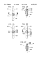
- FIG. 2 is a longitudinal sectional view showing the valve assembly of the first embodiment and a small portion of the aerosol container, with the valve assembly in its closed position;
- FIG. 3 is a view similar to FIG. 2, but showing the valve assembly in its open position
- FIG. 4 is a view similar to FIG. 3, but showing a second embodiment of the present invention, where the valve assembly has a different arrangement for the vent openings of the valve assembly;
- FIG. 5 is a drawing similar to FIG. 3, but drawn to an enlarged scale, and giving various dimensions which in a prototype have been proved to be suitable in the present invention.
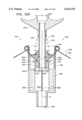
- FIG. 6 is a longitudinal sectional view of a third embodiment of the present invention.
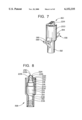
- FIG. 7 is an isometric view of an upper portion of the valve assembly of the third embodiment.
- FIG. 8 is a longitudinal sectional view of that portion of the valve assembly illustrated in FIG. 7;
- FIG. 9 is a longitudinal sectional view of the lower and middle portion of the valve assembly of the third embodiment of FIG. 6, with the valve in the closed position;
- FIG. 10 is a view similar to FIG. 9, but showing the valve in the open position
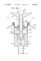
- FIG. 11 is a longitudinal sectional view, similar to FIG. 6, of a fourth embodiment of the present invention.
- FIG. 12 is a longitudinal sectional view of the lower part of the valve assembly of the fourth embodiment of FIG. 11;
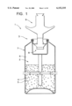
- FIG. 13 is a longitudinal sectional view of a fifth embodiment of the present invention.
- FIG. 14 is a longitudinal sectional view of a sixth embodiment of the present invention.
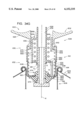
- FIG. 15 is an enlarged longitudinal section view of a portion of the seventh embodiment of FIG. 16, with a broken line circle showing that portion of FIG. 16 enlarged as FIG. 15;
- FIG. 16 is a longitudinal sectional view of a seventh embodiment of the present invention.
- FIG. 17 is a longitudinal sectional view of an eighth embodiment of the present invention.
- FIG. 18 is a top plan view of an actuator assembly that may be used with the present invention.
- FIG. 19 is a longitudinal section view taken along lines 19--19 of FIG. 18;
- FIG. 20 is a top plan view of another actuator assembly that may be used with the present invention.
- FIG. 21 is a front elevational view of the actuator assembly of FIG. 20;
- FIG. 22 is a longitudinal section view taken along lines 22--22 in FIG. 21;
- FIG. 23 is a top plan view of yet another actuator assembly that may be used with the present invention.
- FIG. 24 is a longitudinal section view taken along lines 24--24 of FIG. 23;
- FIG. 25 is a top plan view of still another actuator assembly that may be used with the present invention.
- FIG. 26 is a top plan view of another actuator assembly that may be used with the present invention.
- FIG. 27 is a longitudinal section view taken along lines 27--27 in FIG. 26;
- FIG. 28 is a top plan view of yet another actuator assembly that may be used with the present invention.
- FIG. 29 is a longitudinal section view taken along lines 29--29 in FIG. 28;
- FIG. 30 is a top plan view of another actuator assembly that may be used with the present invention.
- FIG. 31 is a longitudinal section view taken along lines 31--31 in FIG. 30.
- FIGS. 32A-D depict a ninth embodiment of a dispensing system of the present invention having a metering assembly to facilitate application of a predetermined quantity of acoustic texture material;
- FIGS. 33A-D are section views depicting a tenth embodiment of a dispensing system of the present invention.
- FIGS. 34A-G are section view of an eleventh embodiment of a dispensing system of the present invention.
- FIGS. 35a-G are section views taken along a different plane and corresponding to FIGS. 34A-G;
- FIG. 36 is a section view taken along lines 36--36 in FIG. 34A;
- FIG. 37 is a section view taken along lines 37--37 in FIG. 34A;
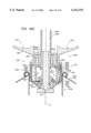
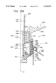
- FIG. 38 is a section view of a twelfth embodiment of the present invention.
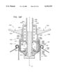
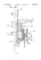
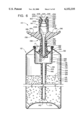
- FIG. 39 is a partial section view of a dispensing system of a thirteenth embodiment of the present invention.
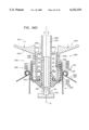
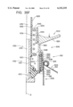
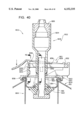
- FIG. 40 is a section view of a dispensing system of a fourteenth embodiment of the present invention.
- FIG. 41 is a section view taken along lines 41--41 in FIG. 40;
- FIG. 42 is a section view taken along lines 42--42 in FIG. 40;
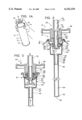
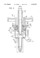
- FIG. 43 is a section view of a fifteenth embodiment of a dispensing system of the present invention.
- FIG. 44 is a side elevational view of the dispensing system of FIG. 43;
- FIG. 45 is a section view taken along lines 45--45 in FIG. 43;
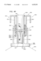
- FIG. 46 is a side elevational view of a dispensing system of the sixteenth embodiment of the present invention.
- FIG. 47 is a section view of the dispensing system depicted in FIG. 46.
- FIG. 48 is a partial section view taken along lines 48--48 in FIG. 46.
- the present invention is an aerosol dispensing system 1 comprising a number of individual components that are designed to work together in a manner that allows acoustic texture material to be applied to a surface to be coated.
- the aerosol dispensing system 1 comprises a fluid portion 2 and a mechanical portion 3.
- the fluid portion 2 comprises a hardenable acoustic texture material 4 containing particles 5 and a propellant material 6.
- the mechanical portion 3 comprises a container assembly 7, a valve assembly 8, and an actuator assembly 9.
- the fluid portion 1 of the dispensing system and method of the present invention comprises the material 4 to be dispensed, hereinafter the acoustic texture material or hardenable material, and the propellant material 6.
- the Applicants determined that, in the context of applying ceiling texture material to an interior surface such as a ceiling, the composition of the hardenable material was limited by the result desired.
- the Applicants determined that the hardenable acoustic texture material 4 must, at a minimum, include polystyrene chips or beads as the particles 5 in order to obtain a textured surface that would satifactorily match the surrounding original textured surface.
- the particles may be polystyrene, cork or other types of foam material, such as 88% polyethylene and 12% ethylene vinyl acetate, natural or synthetic rubber, elastomer, etc.
- foam material such as 88% polyethylene and 12% ethylene vinyl acetate, natural or synthetic rubber, elastomer, etc.
- the Applicants determined that, in order to develop an aerosol product that would obtain acceptable results for patching a textured ceiling, commercially available ceiling spray texture material as has long been used by prior art non-aerosol spray texture devices is preferably used as part of the hardenable material.
- the hardenable material 4 may include:
- the PurTex product basically comprises a calcium carbonated, mica, and/or clay as filler material, natural and/or synthetic binder, a preservative, and polystyrene chopped beads.
- the hardenable material may also comprise the following ingredients:
- This texture material is a mixture that comprises a carrier fluid component and a particulate material having particles which are mixed throughout the carrier fluid.
- the particulate material is made from an expanded polystyrene having a predetermined particle size.
- the particles of the mixture have a variety of sizes to provide a texture surface having different particle sizes.
- One preferred formulation of the texture mixture is comprised of the following ingredients:
- a thickener that controls the film integrity of the composition
- a pigment component (often a whitener);
- the commercially available ceiling texture material basically comprises calcium carbonate, mica, and/or clay as a filler, a synthetic or natural binder, a preservative, and polystyrene chopped beads.
- Tables A-F Attached hereto in Appendix A are Tables A-F. These tables contain the formulas employed by the Applicants to obtain the hardenable material dispensed by the present invention. Currently, the formula contained in Table F describes the preferred commercial form of the hardenable material dispensed by the present invention.
- PMO 30 is a preservative
- BENTONE LT is a thickener
- NUOSEPT 95 is a preservative
- KTPP is a surfactant
- COLLOIDS 648 is a defoamer
- BUSAN 11M1 is a filler, preservative, antifoamant, dispersant
- TITAN 2101 l is a white pigment
- MINUGEL 400 is a thickener
- BENTONE EW is a thickener
- FOAMASTER 1119A is a defoamer.
- the other major component of the fluid portion 2 is the propellant material 6.
- the propellant employed may be a compressed inert gas such as air or nitrogen that is separate from and acts on the hardenable material.
- the propellant may also be comprised of 50% propane and 50% isobutane, but the particles, or aggregate, cannot be formed of polystyrene in this case.
- the hardenable acoustic texture material 4 should, for aesthetic purposes, include the polystyrene chips or beads 5.
- the propellant material 6 is preferably a compressed inert gas.
- Appropriate inert gasses include air, nitrogen, or a combination thereof. The compressed inert gas will not adversely affect the hardenable material 4 and, in particular, will not dissolve or otherwise cause the deterioration of the polystyrene chips or beads 5 contained therein.
- valve assembly 8 is mounted within the container assembly 7, and the actuator assembly 9 is mounted on the valve assembly 8.
- the valve assembly 7 is normally in a closed configuration in which fluid, namely the hardenable material 4, is prevented from exiting the container assembly 7.
- the operator depresses the actuator assembly 9 to place the valve assembly 7 into its open configuration.
- an exit passageway is created that allows fluid to flow out of the container assembly 7 through the actuator assembly 9.
- the container assembly 7 is generally conventional, except that it may be modified slightly as necessary to mount the valve assembly 8 and actuator assembly 9.
- valve assembly 8 and actuator assembly 9 are unique to the present invention and will be described as necessary below in the discussion of the preferred embodiments.
- the apparatus 10 of the present invention comprises an aerosol container 12 defining a main pressure chamber 13, and having at its upper end 14 a valve assembly 16.
- the container 12 has an overall cylindrical configuration, comprising a cylindrical sidewall 17, a top wall 18 (either integral with the sidewall 17 or made separately), and a bottom wall (not shown for ease of illustration).
- the valve assembly 16 is mounted at the center of the top wall 18.
- the valve assembly 16 comprises a valve housing 20 mounted to the top container wall 18, and a valve stem or element 22 positioned within the housing 20 for movement between the closed position of FIG. 2 to the open position of FIG. 3.
- a manually operable actuating and discharge portion 24 comprising a mounting portion 26, a cross bar 28, a discharge nozzle 30 extending upwardly from the mounting portion of 26, and a pair of positioning legs 32 extending downwardly from the mounting portion 26 and positioned diametrically opposite from one another.
- the valve housing 20 comprises an annular mounting collar 34 having an outer circumferential mounting lip 36, having in cross section a semi-circular configuration so as to provide a downwardly facing circular recess to be attached to a matching circular lip formed in the top wall 18 of the container 12.
- the collar 34 extends downwardly a short distance from the lip 36 as a side wall 38 and has a lower inwardly extending annular wall portion 40.
- the valve housing 20 also comprises a lower cylindrical housing portion 42 which defines a lower valve chamber 44 located at the lower end of the valve stem 22, and a lower wall 45. Extending downwardly from the housing portion 42 is a lower intake tube 46. It will be noted that there is formed in the lower wall 45 of the housing portion 42 a plurality of vent openings 47 positioned radially outwardly of a tube 46 and leading from the main chamber 13 in the container 12 into the lower valve chamber 44. The function of these vent openings 47 will be discussed later herein in connection with the overall operation of the apparatus 10 of the present invention.
- the tube 46 has an upper end 48 connecting to the center part of a lower wall 45 of the housing portion 42 and a lower end 52 that is positioned at the lower end of the container 12.
- This tube 46 defines a vertical passageway 54 extending from the lower intake opening 56 of the tube 46 upwardly to an upper outlet opening 58 leading into the lower valve chamber 44.
- the lower housing portion 42 has a downwardly extending stub 60 that fits within the upper end of the tube 46 and defines the upper opening 58.
- this fitting 22 comprises an upper tubular portion 64, a lower seal portion 66 and a middle connecting portion 68 interconnecting the upper tubular portion 64 and lower seal portion 66.
- This intermediate fitting 62 can be made of a moderately flexible rubber or synthetic rubber material, and it performs a number of functions.
- the upper tubular portion 64 serves as a resilient spring member which urges the valve element 22 toward its upper closed position of FIG. 2.
- the lower seal portion 66 serves to create a seal between the valve element 22 and the valve housing 20 in the closed position of FIG. 2.
- the connecting portion 68 functions to position the valve element 22 relative to the housing 20, and also interconnects portion 64 and 66.
- the valve element 22 has an overall cylindrical configuration and defines a central vertical discharge passageway 70 that leads to the nozzle 30 that defines the upper portion 72 of the passageway 70.
- the upper part of the valve element 22 has exterior threads 73 which interconnect with the interior threads formed in the mounting portion 26 of the actuating and discharge portion 24.
- the lower middle portion 74 of the valve element has the same cylindrical configuration as the upper portion, with a smooth outer surface, and the upper tubular portion 64 of the flexible fitting 62, in the closed position of FIG. 2, fits snugly around the outer surface of this lower cylindrical portion 74.
- a circular horizontal closure disc or plate 76 that closes the lower end of the discharge passageway 70.
- the upper perimeter surface of this closure planar disc 76 fits against a lower circumferential seal surface 78 of the seal portion 66 of the fitting 62.
- the upper circular edge of the tubular portion 64 bears against an annular protrusion 82 of the valve element 22.
- the lower end of the tubular portion 64 has a moderately expanded circumferential lip 84 that extends over and engages the inner edge of the lower housing wall 40 that defines an opening that receives the flexible fitting 62 and the valve element 22.
- this has in cross section a generally frusto conical configuration, with an inner cylindrical wall that fits around the lower part of the valve element 22.
- the upper circumferential surface 86 of the seal portion 66 fits against the lower surface of the inner lower wall 40 of the housing collar 34.
- the aforementioned seal surface 78 is in sealing engagement with the upper surface of the closure plate 76 of the valve element 22 so as to form a seal so that the texture material that is positioned in the valve chamber 44 is sealed from the discharge passageway 70 in the valve element 22.
- the texture material within the container 12 is a mixture that comprises a carrier fluid component and a particulate material having particles which are mixed throughout the carrier fluid.
- the mixture is contained within the container 12 at a predetermined pressure level which is above ambient pressure. At this predetermined pressure level a propellant portion of the carrier fluid remains liquid. Normally, there will be gas in the form of vaporized propellant in the upper portion of the container 12 in pressure equilibrium with the liquid phase. However, when the pressure is reduced to a predetermined lower level, this propellant component vaporizes.
- the particulate material is made from a polystyrene material having a predetermined maximum particle size (e.g. an eighth of an inch), with each particle being compressible to a smaller particle size dimension.
- a predetermined maximum particle size e.g. an eighth of an inch
- the particles of the mixture will have a variety of sizes, to provide a varying texture surface.
- Other compressible materials, such as cork, that are compatible with the fluid components could be used.
- the apparatus 10 is provided to the end user with the pressurized texture material mixture contained within the container 12, and with the particulate material distributed throughout the liquid component.
- the actuating and discharge portion 24 remains in the closed position of FIG. 2, where the valve element 22 is in the closed position.
- the apparatus 10 is grasped in a person's hand as indicated in FIG. 1A, with two of the person's fingers engaging the opposite sides of the cross bar 28 to depress the cross bar 28 so as to move the valve element 22 downwardly, against the urging of the tubular portion 64 of the intermediate flexible fitting 62 so as to open the intake openings 80 of the valve element 22.
- other types of handles and triggering mechanisms could be used.
- valve element 22 With the valve element 22 in the open position of FIGS. 3 or 5, it can be seen that the lower valve chamber 44 becomes exposed to ambient pressure through the valve element openings 80.
- the pressurized material in the main chamber 13 forces the texture material upwardly through the tube 46 into the valve chamber 44, with the material flowing from this chamber 44 into the openings 80 and thence out the discharge passageway 70.
- the vaporized propellant portion of the fluid component of the texture material passes upwardly through the vent openings 47 into the valve chamber 44 and mixes and/or atomizes. This increases the percentage of the gaseous component of the carrier fluid that is passing into and through the valve chamber 44 and out the passageway 70.
- the particular arrangement of the present invention functions to reliably pass the particles in the mixture through the intake openings 80 to be discharged out the passageway 70.
- the fluid component of the mixture is able to have at least the vaporizable portion thereof pass upwardly through the tube 46 into the chamber 44, with this component vaporizing at least partially to form gaseous bubbles in the texture mixture.
- a propellant in gaseous form or dissolved in a medium at higher pressure could be utilized. By imperical testing, it is believed that the vaporizable portion or propellant serves at least two functions.
- FIG. 4 A second embodiment of the present invention is shown in FIG. 4. This is substantially the same as the first embodiment, except that the vent openings (designated 47a) are positioned in the sidewall of the housing 42a so that these direct flow laterally into the chamber 44a at the location of the intake openings 80a. It is surmised that this location of the vent openings 47a are able to be oriented to effect a tangential swirling pattern, or oriented more radially to provide a more direct force, in the vicinity of the openings 80a to enhance proper movement of the particles.
- FIG. 5 is an enlarged view giving in inches the dimensions of a prototype built in accordance with the teachings of the present invention, and also to show the components more clearly. It is to be recognized, of course, that these dimensions could be increased or decreased within certain limits (e.g. ten percent, twenty percent, or possibly as high as fifty percent or higher, and in some instances changed to provide different proportional relationships in these dimensions) to obtain certain design objectives. Further, the openings 80 could be made moderately larger than the maximum dimension of the particles, or in some instances even smaller than the particle dimension, if the particles are sufficiently compressible.
- FIG. 6 illustrates at 110 of the a third embodiment of the present invention which is particularly adapted to apply an acoustic texture material to the surface of a ceiling.
- This apparatus 110 comprises a container 112 and a discharge assembly 114.
- the container 112 defines a chamber 116 having a texture material containing portion 118 and a propellant containing portion 120.
- the texture material containing portion 118 is located in the bottom part of the chamber 116 since the apparatus 110 is normally operated in a vertically aligned position so that the texture material 122 is positioned by gravity in the lower part of the chamber 116.
- the propellant containing portion 120 is in the upper part of the chamber 116, and the propellant 124 is a gaseous substance which is substantially inert, such as nitrogen or atmospheric air, relative to the texture material 122.
- the propellant 124 is a gaseous substance which is substantially inert, such as nitrogen or atmospheric air, relative to the texture material 122.
- the container 112 comprises a cylindrical side wall 130, having an upper frusto-conical wall section 132, and a bottom wall 134.
- the discharge assembly 114 comprises an infeed section 136 and a valve section 138.
- the infeed section 136 comprises a feed tube 140 having a lower open end 142 positioned adjacent to and just above the bottom wall 134, and an upper end 144 which fits within a downwardly extending stub 146 that is part of an entry chamber housing 148 that defines an entry chamber 150.
- the texture material 122 is forced by pressure from the propellant 124 to flow into the lower open end 142 of the tube 140 and into the entry chamber 150. From this chamber 150, the texture material flows into the valve section 138.
- the valve section 138 comprises a mounting collar 152 (sometimes referred to as a "cup"), a flexible valve seal and mounting member 154, a valve stem 156, a valve handle portion 158, a positioning spring 159, and an end nozzle section 160.
- the valve mounting collar 152 has a perimeter portion 162 which extends upwardly from the collar side wall 163 to curve upwardly and outwardly and then downwardly in approximately a 180° curve.
- This perimeter portion 162 is positioned over a circumferential lip 164 that is formed from an inner circumferential edge of the upper wall 132 and extends in a circle around the inside edge of the frusto-conical upper wall 132.
- This lip 164 at its inner edge is curved (as seen in cross section) upwardly, outwardly and then downwardly in a curved configuration so as to fit within the curved perimeter portion 162 of the mounting collar 152.
- a significant feature of the present invention is the manner in which this mounting collar 152 forms a seal with the upper container wall 132 and also forms a seal with the aforementioned entry chamber housing 148. More particularly, the entry chamber housing 148 comprises a bottom wall 166 and a cylindrical side wall 168. The walls 166 and 168 are made integrally of a semi-rigid plastic material which is able to yield moderately.
- the upper edge 170 of the side wall 168 has its thickness dimension reduced to a very small thickness so as to be reasonably flexible. Then the upper edge portion is formed in a curve 170 that extends upwardly and inwardly, and then outwardly in a somewhat downward curve, this curved portion being indicated at 174, so that this upper curved portion 174 of the chamber member side wall 168 fits snugly between the collar perimeter portion 162 of the collar 152 and the circular lip 164 of the upper container wall 132.
- edge portion 174 of quite thin material (which then can be formed in a circular curve), stresses that might be created in thus attaching the upper edge portion 174 to the container lip 164 are not transmitted into the side wall 168 of the entry chamber housing 148.
- This connection of the perimeter portion 162, circular lip 164 and the curved section 174 can conveniently be provided as follows.
- the inner edge of the container upper wall 132 is preformed to form the circular lip 164, and the collar 152 is also preformed with its semi-circular perimeter portion 162.
- the upper curved section of the entry housing 148 can either be preformed with its upper curved section 174, or this curve 174 can be made at the time of assembly.
- the entry housing 148 with the tube 140 already mounted therein is positioned within the container 112 with the upper edge portion 174 of the housing sidewall 168 overlying the container lip 164.
- the mounting collar 152, with the seal and mounting member 154 and the valve stem 156 already mounted thereto is positioned in the opening at the upper end of the container 112, with the collar perimeter portion 162 overlying the curved portion 174.
- an expanding tool is positioned within the collar 152 and is operated to push radially outwardly against the sidewall 163 of the collar 152 at approximately the location 175 to expand the collar sidewall at the location outwardly a short distance so that it forms a slanted wall section that engages part of the underside of the container lip 164.
- the valve seal and mounting member 154 in terms of function has two portions, namely a lower seal portion 178, and second a mounting portion 180.
- the mounting portion 180 has a center opening 181 and fits within the inner circular edge of a lower wall 182 of the mounting collar 152.
- the mounting portion 180 has a lip or shoulder 183 that extends over the inner edge of the wall 182, and the seal portion 178 fits against the lower surface of the wall 182.
- the mounting portion 180 serves to support the valve stem 156 in the opening 181, with the valve stem supporting the valve handle portion 158 and the end nozzle section 160.
- the seal portion 178 forms a seal not only for the inlets of the valve stem 156, but also forms a seal with the lower collar wall 182.
- valve stem 156 there is a vertical tubular portion 184 that has as its lower end a closure disk or plate 186 which in the closed position abuts against the lower circular edge 188 of the seal portion 178.
- the lower part of the tubular portion 184 of the stem 156 has two laterally extending openings 189. In the closed position of FIG. 6, the seal portion 178 closes these two openings 188.
- the upper end portion 190 of the tubular stem portion 184 has external threads so that it can be connected to the handle portion 158.
- the valve handle portion 158 has a lower cylindrical mounting portion 192 which is internally threaded and fits in threaded engagement onto the upper end 190 of the valve stem tubular portion 184.
- This handle portion 158 has two outwardly extending actuating members or handle members 194 extending in opposite directions from one another, each of these members 194 having an upwardly concavely curved surface 196 to be engaged by the fingers of the person.
- the spring 59 is deformed downwardly so as to provide a restoring force to move the handle portion 158 upwardly when the handle portion 158 is released.
- the upper part of the handle portion 158 comprises a tubular extension 200 that is connected to the end nozzle section 160.
- the tubular portion 184 of the valve stem 156 defines an upwardly extending through passageway 202 which lead into an expanded passageway section (generally designated 204) formed in the upper end portion 200 of the handle portion 158 in conjunction with the upper nozzle section 160.
- the valve handle portion 158 is formed so that immediately above the threaded mounting portion 192, there is an initial lower passageway portion 206 which receives the very upper end of the valve stem 176, and defines an upper passage entry portion 208.
- This passageway portion 208 lead into an upwardly and outwardly expanding passageway portion 210 which in turn leads into an inside surface portion 212 of a greater diameter, the surface portion 212 in effect defining an expansion chamber 214 which is part of the expanded passageway portion 204. From the chamber 214, the passageway portion 204 diminishes in cross-sectional area in an upward direction, and this uppermost converging passageway section is formed by the nozzle section 160.
- This nozzle section 160 is made of two molded parts which are half sections which fit within the valve handle upper portion 200 and are joined to one another along a vertical center plane as two side by side sections. There is a lowermost circular portion 216 having its diameter smaller than the diameter of the chamber surface portion 212. Immediately above the section 216 there is a further necked down section 218, and this connects to an upwardly and inwardly slanted portion 219 to a further upward portion 220 which defines a yet smaller cylindrical passageway section 222 that leads into an end nozzle portion 224.
- This end nozzle section 224 comprises two plate sections or flanges 226 which define therebetween an elongate laterally extending slot 228. These two plate sections 226 converge toward one another to form the end slot 228. In addition, as can be seen in FIG. 6, at opposite ends of the two flanges 226 there are laterally and outwardly extending connecting portions 230 which have outwardly slanting upwardly facing surface portions 232.
- this passageway at 222 is transformed in an upward direction from a cylindrical passageway to a passageway which converges in one direction (caused by the plates 226 slanting toward one another), and expands in a direction 90° from the first direction (caused by the outward slant of the surfaces 232 of the connecting portions 230).
- the texture material 122 within the container 112 is a mixture that comprises a carrier fluid component and a particulate material having particles which are mixed throughout the carrier fluid.
- the gaseous propellant 124 in the upper chamber portion 120 is at a predetermined pressure level which is above ambient pressure (e.g. 100 PSI).
- the particulate material is made from an expanded polystyrene having a predetermined maximum particle size (e.g. the larger particles averaging about 1/8 of an inch across), with each particle being compressible to a smaller particle size dimension.
- a compression test of a preferred form of the material indicates that under 100 PSI pressure, the volume is decreased from 100% down to 25% of the original volume).
- the particles of the mixture has a variety of sizes to provide a texture surface having different particle sizes. While this polystyrene material is the preferred material, within the broader scope of the present invention other materials (desirably compressible materials) could be used.
- the apparatus 110 is provided to the end user with the texture material mixture contained within the container, and with the particulate material distributed throughout the fluid component.
- the texture material 22 occupies at least approximately one half of the volume of the chamber 116 or possibly somewhat more than half the volume of the chamber 116. Since the apparatus 110 is commonly operated in a vertical position to apply the spray texture material upwardly to a ceiling, the texture material 122 is normally positioned in the bottom of the container 112. In use, the apparatus 110 is grasped in a person's hand, with two of the person's fingers engaging the upper surfaces 196 of the handle members 194 to depress the handle portion 158 and the valve stem 156 against the urging of the spring 159.
- the texture material 124 flows through the passageway 202 of the valve stem 156 into the expansion chamber 204, and thence upwardly through the converging passageway portion defined by the nozzle portion 160.
- the texture material expands laterally in the end nozzle portion 224 in one direction, while the passageway is diminished in the direction 90° to the first direction.
- the material exiting from this elongate nozzle opening 228 is disbursed upwardly and somewhat laterally to be applied to the surface (which, as indicated previously, would usually be a ceiling to which an acoustic texture material is applied.
- the texture mixture may comprise one or more the following ingredients:
- a thickener that controls the film integrity of the composition
- a pigment component (often a whitener);
- the texture material When deposited on the surface, the texture material hardens to form the finished textured surface.
- FIGS. 11 and 12 A fourth embodiment of the present invention is illustrated in FIGS. 11 and 12. Components of this fourth embodiment which are similar to components of the third embodiment will be given like numerical designations, with an "a" suffix distinguishing those of the second embodiment.
- the apparatus 110a comprises a container 112a and a discharge assembly 114a.
- the discharge assembly 114a does not have the feed tube 140 and the entry chamber housing 148 that are present in the third embodiment 110, shown in FIGS. 6 through 10.
- the texture material 122a instead of being positioned by gravity in the bottom of the container 112a, is contained in a flexible sack-like container 240 that forms the texture material chamber 118a immediately adjacent to the valve section 138.
- the propellant 124a is separated from the texture material 122a by the flexible container 240, and this propellant 124a is a vaporizable liquid which when under pressure in the container remains liquid, but with a small pressure reduction vaporizes to form a gas which pushes against the texture material 122a.
- an elongate spring 242a which is positioned vertically in the texture material chamber 118a.
- the upper edge of the flexible container 240 is placed in a curve over the inner rounded edge 164a of the container upper wall 132a, and beneath the curved perimeter portion 162a of the collar 152a, in the same manner as the rounded portion 174 of the entry chamber housing of the third embodiment.
- valve section 138a which comprises a mounting collar 152a, the seal and mounting member 154a, the valve stem 156a, the valve handle portion 158a, and the end nozzle section 160a. All of these components 152a through 160a are substantially the same as in the third embodiment, except that the positioning spring 159 of the third embodiment is omitted.
- the seal and mounting member 154 is provided with an upwardly extending resilient tube portion 244 that is made integral with the seal and mounting member 154. When the handle portion 158a is depressed, this deforms this resilient tubular portion 244 outwardly so as to be axially compressed.
- the flexible container 240 collapses, with the propellant 124a expanding in the propellant chamber 120a.
- FIG. 13 of the drawing depicted therein at 320a is a spray texturing device constructed in accordance with of, and embodying, the principles of a fifth embodiment of the present invention.
- This device 320a is adapted to contain and dispense a hardenable material 322.
- the hardenable material 322 comprises a commercially available ceiling texture material 324 containing polystyrene particles 326.
- the aerosol device 320a basically comprises a container 328, a cap 330, and a collection tube 332.
- the cap 330 mounts the collection tube 332 within an opening 334 in the container 328 such that a first end 336 of the collection tube 332 is within the container 328 and a second end 338 of the collection tube 332 extends out of the container 328.
- the hardenable material 322 is contained within a chamber 340 defined by the container 328.
- the collection tube first end 336 extends into the hardenable material 322.
- a port 342 is formed in the container 328 to allow pressurized air to be introduced into the chamber 340.
- the introduction of pressurized air through the port 342 into the chamber 340 forces the hardenable material 322 into the collection tube first end 336, through the collection tube 332, and out of the collection tube second end 338.
- the aerosol device 320a in its most basic form employs a compressed inert gas such as air to force a hardenable material containing particulates upwardly out of the container 328.
- FIG. 14 depicted therein at 320b is sixth embodiment of an aerosol device constructed in accordance with, and embodying, the present invention.
- the aerosol device 320b is constructed and operates in the same basic manner as the device 320a above.
- the device 320b further comprises a manifold 344 at which a vapor tap tube 346 is connected to the dispensing tube 332. Compressed air injected into the tube 346 will mix with the hardenable material 322 exiting the dispensing tube 322 near the dispensing tube second end 338 to atomize the hardenable material 322 as it leaves the tube 332.
- the hardenable material 322 By vaporizing the hardenable material 322 as it leaves the dispensing tube 332, the hardenable material 322 sprays as it leaves the device 320b as is the tendency with the material 322 as it leaves the aerosol device 320a described above. While a stream of hardenable material 322 can be used to patch a ceiling, the spray developed by the aerosol device 320b more evenly and effectively distributes the hardenable material onto the ceiling.
- a valve 348 was employed to vary the amount of air used to atomize the hardenable liquid 322.
- FIGS. 15 and 16 depicted therein is yet another exemplary aerosol device 320c constructed in accordance with, and embodying, the principles of a seventh embodiment of the present invention.
- Elements of the aerosol device 320c that are the same as those of the device 320a are assigned the same reference character and will be described herein only to the extent that they differ from the corresponding element of the device 320a.
- the aerosol device 320c fundamentally differs from the devices 320a and 320b described above in that the device 320c employs a vaporizable liquid 350 to propel the hardenable material 322 from the container 328.
- the vaporizable liquid 350 can be a hydrocarbon material as is well known in the art.
- the device 320c further comprises a valve assembly 352 for allowing the operator to open or close a dispensing passageway 354 through which the hardenable material 322 is discharged.
- the vaporizable material 350 vaporizes and becomes a gas which collects in an upper portion 356 of the chamber 340. This gas acts on the hardenable material 322 to force this material through the discharge passageway 354 and out of the container 328.
- a texture material 354 comprising particles 356 of material other than polystyrene should be used.
- the liquid hydrocarbon will dissolve polystyrene particles. Accordingly, the particles 356 should be formed of cork or other materials that will not be dissolved by the liquid hydrocarbons.
- the aerosol device 320c is not optimized for use as a ceiling texture material dispenser because the particles 356 will either bounce off of the ceiling or will not adequately match the texture of the surrounding ceiling.
- the valve assembly 352 is constructed and operates in the same basic manner as the valve section 138 described above with reference to FIG. 6 and will be described herein only briefly.
- the valve assembly 352 basically comprises a housing 362, a valve seat 364, and a valve member 366 having a valve stem 368.
- the discharge tube 332 is connected to the valve housing 362.
- the valve assembly 352 is opened by downwardly pressing the valve stem 368.
- the discharge passageway 354 is defined by the discharge tube 332, valve housing 362, and valve member 366.
- FIG. 17 depicted at 320d therein an eighth embodiment of an aerosol device constructed in accordance with, and embodying, the principles of the present invention.
- the aerosol device 320d is constructed in a manner basically similar to that of the device 320a described above. Components of the device 320d that are the same as those of the device 320a described above will be assigned the same reference character and described below only to the extent necessary for a complete understanding of the operation of the device 320d.
- the aerosol device 320d comprises a piston member 370 arranged within the container 328 such that the chamber 340 is divided into a first portion 372 and a second portion 374.
- the hardenable material 322 including the ceiling texture material 324 comprising polystyrene particles 326 is arranged in the first portion 372 of the chamber 340.
- the chamber second portion 374 contains a propellant material such as a vaporizable hydrocarbon liquid or a compressed inert gas such as air or nitrogen.
- a valve assembly 378 is mounted to the cap 330 within the opening 334 in the cannister 328.
- This valve assembly 378 comprises a valve seat 380 and a valve member 382 having a valve stem 384. Depressing the valve stem 384 downwardly allows the hardenable material 324 within the chamber first portion 372 to flow through an exit passageway 386 to the exterior of the container 328.
- the discharge passageway 386 is defined by the valve member 382.
- the piston member 370 thus separates the hardenable material 324 from the propellant material 376, allowing the use of liquid hydrocarbons as a propellant material.
- a perfectly fluid-tight seal around the perimeter of the piston member 370 cannot be maintained; thus, over time, the propellant material 376 may seep into the chamber first portion 372 and, if the propellant material 376 is a liquid hydrocarbon and the particles 326 are polystyrene, dissolve these particles 326.
- the liquid propellants used gassify as the exit the aerosol device with the texture material; the gassifying liquid propellant causes the texture material to exit the aerosol device in the form of a conical spray rather than a stream.
- the acoustic texture material dispensed by any of the various dispensing assemblies described herein uses compressed inert gas as a propellant rather than a conventional liquid propellant, the texture material is not broken up into a spray and thus tends to exit the aerosol device in a stream rather than a spray.
- dispersion means are preferably employed to disperse the texture material as it exits the aerosol device such that the texture material exits in a fan-shaped or conical spray.
- Dispersion means such as are depicted in FIGS. 18-31 and as described below may be used with any of the dispensing assemblies or aerosol devices described herein to prevent the acoustic texture material from being deposited in the form of a narrow stream.
- FIGS. 18 and 19 depicted therein at 420a is an exemplary dispersion assembly constructed in accordance with, and embodying, the principles of the present invention.
- depicted at 422 is a hollow tube corresponding either to a second end of a discharge tube such as the discharge tube 322 shown and described in relation to FIGS. 13 and 14, or a stem portion of a valve assembly such as the valve assembly 352 and 378 described and shown in FIGS. 16 and 17.
- This hollow tube 422 defines a discharge axis A shown by broken lines in FIG. 19.
- the dispersion assembly 420a is mounted on this tube 422.
- the dispersion assembly 420a comprises a mounting member 424 and a deflecting member 426.
- a discharge opening 428 is formed in the mounting member 424.
- the mounting member 424 is attached to the tube 422 such that the discharge opening 428 is aligned with a discharge passageway 430 defined by the tube 422.
- the discharge opening 428 comprises a cylindrical upper portion 432 and a frustoconical lower portion 434.
- the lower portion 434 reduces the diameter of the discharge passageway 430 from the inner diameter of the tubular member 422 to the diameter of the opening upper portion 432.
- the discharge opening 428 thus forms a nozzle that accelerates the hardenable material flowing along the discharge passageway.
- the deflection member 426 is generally hook-shaped and connected to the attachment member such that a portion 436 thereof coincides with the discharge axis A.
- the hardenable material passes through the discharge opening 428, it contacts the deflection member 426 such that at least a portion of the hardenable material has a vector component that radially extends outward from the discharge axia A.
- the dispersion assembly 420a thus causes the hardenable material to form a spray rather than a stream. This makes it easier for the user to apply hardenable material to a surface in an even pattern.
- Handles 425 are formed on the attachment member 424 to allow the user to displace the tubular member 422 downwardly along the discharge access A.
- FIGS. 20-22 depicted at 420b therein is yet another exemplary dispersion assembly constructed in accordance with, and embodying, the principles of the present invention.
- the dispersion assembly 420b is constructed and operates in the same basic manner as the dispersion assembly 420a described above; accordingly, the dispersion assembly 420b will be described herein only to the extent that it differs from the dispersion assembly 420a.
- the dispersion assembly 420b comprises a deflection member 438 extending from the attachment member 424 above the discharge opening 428.
- the deflecting member 438 has a deflecting surface 440 formed thereon.
- the deflecting surface 440 is arranged such that it intersects the discharge axis A. Accordingly, as hardenable material flows along this axis A, the material will contact this deflecting surface 440. After it has been so deflected, at least a portion of the hardenable material will have a vector component in a direction radially extending from the discharge axis A. As with the dispersion assembly 420a described above, the dispersion assembly 420b will thus generate a spray of hardenable material that facilitates the application of this material on the surface to be textures.
- FIGS. 23 and 24 depict an exemplary dispersion unit 420c that is constructed in accordance with, and embodies, the principles of the present invention.
- This dispersion unit 420c operates in the same basic manner as the dispersion assembly 420a and will be described herein only to the extent that it differs therefrom.
- the dispersion unit 420c comprises a dispersion member 424.
- the dispersion member 424 has formed therein a nozzle passageway 442 comprising a vertical portion 444 aligned with the discharge access A and a radial portion 446 arranged at an angle to the discharge access A.
- a dispersion surface 448 is arranged at the end of the vertical portion 444 and forms a part of the radial portion 446. As the hardenable material flows along the discharge access A, it will be redirected such that it has a vector component radially extending from the discharge access A.
- the radial passageway 446 is further defined by a lower surface 450. As shown in FIG. 24, the deflecting surface 448 terminates approximately midway along the bottom surface 450.
- FIG. 25 there is depicted yet another exemplary dispersion member 420d constructed in the same basic manner as the dispersion member 420c described above.
- the radial passageway 446 is defined by divergent sidewalls 452 and 454. These diverging sidewalls 452 and 454 allow the hardenable material to fan out as it exits the discharge opening 428.
- FIGS. 26 and 27 there is depicted yet another exemplary dispersion member 420e constructed in the same basic manner as the dispersion member 420d described above.
- the dispersion member 420e further comprises a deflecting member 456 arranged to partially cover the discharge opening 428.
- the deflecting member 456 is generally triangular in shape, with a point being formed substantially equidistant between the diverging sidewalls 452 and 454 defining the radial passageway 446.
- the deflecting member 456 deflects at least a portion of the hardenable material coming out of the discharge opening 428 such that at least a portion of the hardenable material has a vector component that radially extends from an access B of the radial passageway 446. This results in a wider dispersal of hardenable material throughout the spray pattern formed by the dispersion member 424.
- FIGS. 28 and 29, depicted at 420f therein is yet another exemplary dispersion member constructed in accordance with, and embodying, the principles of the present invention.
- the dispersion member 420f operates in a manner similar to the dispersion assembly 420b described above.
- a dispersion member 458 is arranged adjacent to the upper portion 432 of the discharge opening 428.
- the exit opening 428 is rectangular in shape and the deflecting member 458 is arranged with a deflecting surface 464 formed thereon arranged to deflect all of the hardenable material exiting through the discharge opening 428.
- the deflecting surface 464 does not overhang an upper surface 466 of the dispersion member 424f; accordingly, the hardenable material is not channeled in a direction radial to the discharge access A and is allowed to develop into a spray that facilitates application of the hardenable material to the surface to be covered.
- This dispersion member 420g defines a passageway 468 comprising a short vertical portion 470 and a fan-shaped radial portion 472.
- the radial portion 472 has diverging sidewalls 474 and 476 and parallel upper and lower walls 478 and 480. Extending between the upper and lower walls 478 and 480 are a plurality of deflecting member 482 designed to deflect and slow down at least a portion of the hardenable material exiting through the discharge opening 428.
- the fan-shaped arrangement of the radial passageway 472 along with the deflecting member 482 results in a spray of hardenable material that facilitates the application of this material onto a surface.
- the dispensing system 500 includes a mechanical portion 502 that allows the acoustic texture material of the fluid portion to be dispensed in predetermined metered amounts.
- the mechanical portion 502 comprises a container assembly 504, a valve assembly 506, an actuator member 508, and a metering assembly 510.
- a container assembly 504 comprises a container 512, a cap 514, and a mounting flange 516.
- the valve assembly 506 comprises a valve housing 518, a valve stem 520, a valve spring 522, and a valve seal 524.
- the metering assembly 510 comprises a metering member 526 and a plurality of guide flanges 528 extending from the valve housing 518.
- the actuator member 508 is attached to the valve stem 520 by threads, adhesives, or the like.
- the actuator member is configured such that the user can depress downwardly on the actuator member 508 and cause the valve stem 520 to move downwardly along a longitudinal axis x of the mechanical portion 502.
- the cap 514 and mounting flange 516 are attached to the container 512 in a conventional manner.
- the valve housing 518 is attached to the mounting flange 516 such that the valve housing 518 resides within the container 512.
- the valve housing 518 is connected to a pick-up tube such as the tube 46 described above, which creates a fluid path from the bottom of the container 512 to the valve housing 518 as will be described in further detail below.
- valve seal 524 is mounted to the cap 514, and the valve stem 520 is mounted to the valve seal 524 such that the valve stem 520 moves along the axis x as generally described above.
- the valve spring 522 is arranged to oppose motion of the valve stem 520 downward along the axis x.
- the metering member 526 is an annular or ring shaped member that is arranged about a lower portion of the valve stem 520 between a stem portion 520a of the valve stem 520 and the valve seal 524.
- a release flange 530 extends from an upper portion of the metering member 526.
- a release projection 532 is formed on a lower inner portion of the metering member 526.
- a similarly shaped release groove 534 is formed about the valve stem 520 adjacent to the stem portion 520a.
- the release projection 532 is designed to engage the release groove 534, but can be disengaged therefrom by deliberate application of manual force that tends to move the metering member 526 away from the stem portion 520a.
- the metering member 526 further defines a metering surface 536 that has substantially the same cross-sectional area as an outer surface of the stem member 520.
- the mechanical portion 502 is shown in what will be referred to as a storage state.
- the metering member 526 engages the valve seal 524 to prevent fluid from exiting the container 512 through the valve assembly 506.
- the propellant within the container 512 acts on the texture material there within to force the texture material through a housing inlet 538 in the valve housing 518 and into a housing chamber 540.
- the actuator member 508 is displaced downwardly along the axis x such that the metering member 526 disengages from the valve seal 524.
- pressurized fluid within a housing chamber 540 defined within the valve housing 518 may flow through a stem inlet 542 in the valve stem 520, into a stem passageway 546 in the valve stem 520, and out of the mechanical portion 502 through an outlet chamber 548.
- the metering member 526 moves downward with the valve stem 520 creating the dispensing path DP along which the texture material passes as it exits the container 512.
- the release flange 530 engages an upper portion of the guide flanges 528 such that the metering member 526 can no longer move downward along the axis x.
- valve spring 522 is compressed. Accordingly, releasing the actuator member 508 allows the valve spring 522 to urge the valve stem 520 upward. Friction between the valve stem 520 and the metering surface 536 causes the metering member 526 to move upward with the valve stem 520 until the metering member 526 again comes in contact with the valve seal 524. This configuration is shown in FIG. 32D.
- the metering member 526 can no longer move upward with the valve stem 520.
- the valve spring 522 continues to move the valve stem 520 upward until the stem portion 520a thereof engages the metering member 526 as shown in FIG. 32A.
- the release projections 532 engage the release groove 534 such that, if the valve stem 520 again is moved downward, the metering member 526 will be carried therewith. Accordingly, the mechanical portion 502 is returned to its predispensing state shown in FIG. 32A and is ready to be used again.
- the mechanical assembly 502 described above requires no special skill by the user for dispensing the texture material within the container 512.
- the user must simply press downwardly on the actuator member 508 until the valve stem 520 bottoms out as shown in FIG. 32C, then releases the actuator member 508. If these minimal directions are followed, the mechanical portion 502 will dispense a quantity of texture material that is a function of the pressure and volume of the inert gas used as a propellant, the speed at which the stem member 520 is moved downward, the size of the stem inlet 542, and the amount the stem member 520 is allowed to travel before its stem inlets 542 are covered by the metering surface 536. These parameters can be adjusted so that a reasonably consistent amount of texture material is dispensed by even an inexperienced user.
- FIGS. 33A-D depicted therein at 550 is a tenth embodiment of a dispensing system constructed in accordance with, and embodying, the principles of the present invention.
- This dispensing system 550 comprises a fluid portion as described above, and a mechanical portion 552.
- the mechanical portion 552 is designed to dispense a controlled, metered amount of texture material.
- the mechanical portion 552 comprises a container assembly 554, a valve assembly 556, an outlet assembly 558, and a metering assembly 560.
- a container assembly 554 is adapted to contain the fluid portion as described above.
- the valve assembly 556 is mounted on the container assembly 554 and operates in a closed configuration in which fluid may not exit the container assembly 554 and an open configuration in which fluid is allowed to exit the container assembly 554.
- the outlet assembly 558 disperses the texture material exiting the container assembly 554 through the valve assembly 556.
- the metering assembly 560 engages the valve assembly 556 to control the opening and closing of the valve assembly such that only a limited amount of texture material is released when the valve assembly is used as intended.
- the container assembly 554 comprises a container 562 and a cap 564 mounted on the container 562 along a longitudinal axis x thereof.
- the valve assembly 556 comprises a valve housing 566, a valve stem 568, a valve spring 570, and a valve seal 572.
- the valve housing 566 is mounted to the container 562 and cap 564 such that the interior of the container 562 is divided into two separate chambers.
- a pick-up tube is connected to the valve housing 566 to allow fluid at the bottom of the container assembly 554 to enter the valve housing 566.
- the valve seal 572 is mounted on the cap 564, and the valve stem 568 extends through the valve seal 572.
- the valve seal prevents fluid from flowing out of the valve housing 566 between the valve stem 568 and the cap 564.
- valve spring 570 is mounted between the cap 564 and the valve stem 568 such that the spring 570 urges the valve stem upward.
- the valve spring 570 urges the valve stem 568 upward such that the valve stem 568 engages the valve seal 572, in which case the valve assembly 556 is in its closed position.
- the outlet assembly 558 comprises an actuator member 574, and outlet member 576, an outlet cap 578, and an actuator return spring 580.
- the outlet member 576 is rigidly attached to the valve stem 568 by threading and/or adhesives, such that movement of the outlet member 576 is transferred to the valve stem 568.
- the outlet member extends through the actuator member 574 such that relative movement between the outlet member 576 and the actuator member 574 is possible.
- the outlet cap 578 is attached to the outlet member 576 to form a dispersing means as texture material exits the mechanical portion 552.
- the actuator return spring 580 is arranged between the cap 564 and the actuator member 574 to oppose downward movement of the actuator member 574.
- the metering assembly 560 comprises a metering member 582 and a release member 584.
- the metering member 582 is attached to the outlet member 576. Accordingly, movement of the metering member 582 will be transmitted through the outlet member 576 to the stem member 568.
- the valve stem 568, outlet member 576, outlet cap 578, and metering member 582 all form a rigid assembly and can be made as one piece. For manufacturing reasons, however, this assembly comprises four separate molded plastic parts in the exemplary dispensing system 550.
- the release member 584 is fixed relative to the cap 564.
- the actuator return spring 580 physically engages the release member 584 at its lower end and thus holds the release member 584 against the cap 564. Again, this is convenient for manufacturing purposes, but the cap 564 and release member 584 could conceivably be formed by one integrally formed part.
- an actuator surface 586 Formed on the actuator member 574 is an actuator surface 586. Extending from the metering member 582 are metering projections 588. These projections 588 are canted outwardly from the longitudinal axis x, but are sized, dimensioned, and made of a material that allows these projections 588 to deflect inwardly towards the axis x.
- release surface 590 Formed on the release member 584 is a release surface 590.
- the release surface 590 is spaced directly below the actuator surface 586.
- FIG. 33A shows the mechanical portion 552 in a predispensing state in which the valve assembly 556 is closed.
- Applying a downward force on the actuator member 574 causes the actuator surface 586 to engage the metering projections 588 and force the valve stem 568 downward as perhaps best shown in FIG. 33B.
- This dispensing path DP allows pressurized texture material within the valve housing 566 to enter a stem inlet 592 formed in the valve stem 568, flow through a stem passageway formed in the valve stem 568, and enter an outlet chamber 596 defined by the outlet member 576 and outlet cap 578.
- the outlet chamber 596 is in communication with the exterior of the container 562 through an outlet opening 598 defined by the outlet cap 578.
- the outlet opening 598 is sized and dimensioned to disperse the texture material as it leaves the mechanical portion 552.
- valve stem 568 moves downward, it carries the metering projections 588 with it such that these projections 588 come in contact with the release surface 590 on the release member 584.
- valve stem 568 continues downward movement of the valve stem 568 causes the release surface 590 to displace the metering fingers 588 towards the longitudinal axis x such that these fingers 588 are disengaged from the actuator surface 586. At this point, the actuator surface 586 comes into contact with the release surface 590.
- valve stem 568 moves downward, it compresses the valve spring 570. Accordingly, when the metering fingers 588 become disengaged with the actuator surface 586, the valve spring 570 urges the valve stem 568 upward.
- the metering projections 588 slide along the actuator member 574 as shown in FIG. 33D and allow the valve spring 570 to force the valve stem 568 back into its original, uppermost position in which it engages the valve seal 572 to prevent fluid from flowing out of the container 562.
- the actuator member 574 has compressed the actuator member return spring 580. Accordingly, the user need only release the actuator member 574, and the actuator return spring 580 will force the actuator member 574 up relative to the valve stem 568 and metering member 582.
- the actuator member 574 thus returns to its initial position in which the actuator surface 586 is located above the metering projections 588.
- the metering projections 588 are thus allowed to return to their original position in which they are more severely canted outwardly relative to the longitudinal axis x.
- the mechanical portion 552 is thus ready to dispense another metered portion of texture material.
- the dispensing system 550 of the tenth embodiment allows the user to press firmly and continuously down to dispense a limited, controlled, and metered amount of texture material.
- the amount of texture material released is determined by the same factors discussed above with reference to the ninth embodiment.
- the dispensing system 600 comprises a fluid portion as described above and a mechanical portion 602, a portion of which is depicted in the drawing.
- the mechanical portion 602 comprises a container assembly 604, a valve assembly 606, an outlet assembly 608, and a metering assembly 610.
- the valve assembly 606 is mounted on the container assembly and operable in open and close configurations. When the valve assembly 606 is in its closed configuration, fluid is prevented from leaving the container assembly 604.
- the outlet assembly 608 is mounted onto the valve assembly 606 such that, when the valve assembly 606 is in its open configuration fluid, and in particular acoustic texture material, is allowed to flow out of the container assembly 604 through the outlet assembly 608.
- the metering assembly 610 controls the valve assembly 606 such that a predetermined, metered amount of texture material is dispensed.
- the container assembly 604 comprises a container 612 and a cap 614.
- the valve assembly 606 comprises a valve housing 616, a valve stem 618, a valve spring 620, and a valve seal 622.
- the cap 614 is mounted on the container 612 and the valve seal 622 is mounted on the cap 614.
- the valve stem 618 extends through the valve seal 622.
- the valve seal 622 is made of a resilient material that engages the cap 614 and the valve stem 618 such that fluid is not able to flow out of the container 612 between the cap 614 and the valve stem 618.
- the valve housing 616 is mounted to the container assembly 604 such that it is within the container 612 below the cap 614. As with the valve housings of the ninth and tenth embodiments described above, the valve housing 616 is connected to a pick-up tube that extends to the bottom of the container 612. As generally discussed above, the pressurized propellant material is located at the top of the container 612 and the texture material at the bottom of the container 612. Accordingly, the pressurized propellant material forces the texture material through the pick-up tube such that pressurized texture material is present in the valve housing 616.
- valve spring 620 is arranged between the cap 614 and the valve stem 618 such that the valve spring 620 urges the valve stem 618 upward such that the valve assembly 606 is normally biased into its closed position.
- the valve stem 618 engages the valve seal 622 as shown in FIG. 34A.
- the outlet assembly 608 comprises an actuator member 624, and outlet member 626, and an actuator return spring 628.
- the outlet member 626 is rigidly attached to the valve stem 618 by threads, adhesive, or the like such that movement of the outlet member 626 causes movement of the valve stem 618.
- the actuator member 624 is free to move relative to the valve stem 618 and outlet member 626, with the outlet member 626 extending through the actuator member 624.
- the actuator return spring 628 is arranged to urge the actuator member 624 upward; when the actuator member 624 is moved downward, the actuator return spring 628 is compressed.
- the metering assembly 610 comprises a trigger assembly 630 and a release assembly 632.
- the trigger assembly 630 comprises a trigger member 634 and a trigger spring 636.
- the release assembly 632 comprises a release member 638 configured as will be described below.
- the trigger member 634 comprises a plurality of guide fingers 640, a plurality of trigger fingers 642, and a plurality of release fingers 644 that extend downwardly from a trigger plate 646.
- the guide finger 640 and trigger finger 642 are shown in FIG. 34 and in the horizontal section view of FIG. 36.
- the release fingers 644 are shown in FIG. 35 as well as in the horizontal section view of FIG. 36.
- the exemplary mechanical portion 602 comprises three each of these guide fingers 640, trigger finger 642, and release finger 644. More or fewer of these fingers 640-644 may be used, but the use of three each represents a desirable blend of balance during operation and manufacturability.
- an intermediate flange 648 is formed on the outlet member 626.
- the release member 638 comprises a guide cylinder 650, a plurality of support posts 652, and a plurality of release posts 653 that extend upwardly from a base plate 654.
- the base plate 654 is configured to snugly be received within the cap 614.
- the guide cylinder 650 extends upwardly a distance slightly greater than the height of the support posts 652 and release posts 653.
- An actuator surface 656 is formed on the actuator member 624. As shown in FIG. 34, a trigger surface 658 is formed on each of the trigger fingers 642. FIG. 35 shows that a cam surface 660 is formed on each of the release fingers 644. And in FIG. 34, it can be seen that a support surface 662 and release surface 664 are formed on each of the support posts 652.
- the actuator member 624 comprises first and second bearing surfaces 666 and 668 and an actuator cylinder 670.
- the metering assembly 610 is assembled together with the container assembly 604, valve assembly 606, and outlet assembly 608 as follows. After the valve assembly 606 has been mounted onto the container assembly 604 and the outlet member 626 attached to the stem member 618 as described above, the release member 638 is displaced such that the base plate 654 thereof is snugly received by the cap 614 such that the guide cylinder 650 is aligned with the axis x. At this point, the intermediate flange 648 will rest on the support surfaces 662 on the support posts 652. The trigger spring 636 is then placed over the outlet member 626 such that spring 636 is supported at its lower end by the intermediate plate 648.
- the trigger member 634 is then placed over the outlet member 626 such that the trigger spring 636 is arranged between the trigger plate 646 and the intermediate plate 648.
- the trigger fingers 642 must be aligned with the support posts 652 and the release finger 644 must be aligned with the release posts 653.
- the first bearing surface 666 defines a hole in the trigger plate 646 through which the outlet member 626 passes.
- the first bearing surface 666 engages the guide member 626 and the second bearing surfaces 668 on the guide fingers 640 engage the intermediate flange 648 such that the trigger member 634 also can move only along the longitudinal axis x.
- the actuator return spring 628 is then placed around the trigger member 634 until it rests on the base plate 654 of the release member 638.
- the outlet member 624 is then placed over the trigger member 634 such that the actuator cylinder 670 engages the guide cylinder 650 such that the actuator member 624 moves only along the system axis x. In this configuration, the actuator return spring 628 opposes downward motion of the actuator member 624 as generally discussed above.
- the purpose of the metering assembly 610 is generally to allow the user to pull down on the actuator member 624 and initiate a sequence of events that open and close the valve assembly 606 substantially independent from the actions of the user.
- the valve assembly will automatically be closed only if the user pulls the actuator member down past a predetermined point.
- the trigger assembly 630 controls the opening of the valve assembly 606 while the release assembly 632 controls the closing of the valve assembly 606.
- the user merely energizes the metering assembly 610 by compressing various springs and then triggers the automatic sequence of events that opens and closes the valve assembly 606. The user is thus prevent from placing the valve assembly 606 in an intermediate configuration in which texture material is allowed to freely flow from inside the container assembly 604.
- FIGS. 34A and 35A the mechanical portion 602 is shown in its predispensing state in which the actuator member 624 is in its uppermost position and the valve assembly 606 is closed. The user then applies a downward force on the actuator member 624 as shown by arrows in FIGS. 34B and 35B. As shown best in FIG. 35B, the actuator surface 656 engages the trigger member 634 such that the trigger member 634 moves down with the actuator member 624.
- the mechanical portion 602 is in a pretriggering state in FIGS. 34B and 35B in which the actuator return spring 628 and trigger spring 636 are both compressed. At this point, the valve spring 620 is not compressed and the valve assembly 606 is still in its closed configuration. Then, as shown in FIGS.
- the trigger surfaces 658 on the trigger fingers 642 engage the release surfaces 664 on the support posts 652.
- the trigger fingers 642 are supported by the intermediate plate 648 at this point, so the interaction of the trigger surfaces 658 with the release surfaces 664 causes the support posts 652 to deflect slightly away from the system axis x.
- the situation depicted in FIGS. 34C and 35C will be referred to as the triggering state.
- valve assembly In this open state, the valve assembly has been placed in its open configuration, and fluid is free to flow into a stem inlet 672 and through a stem passageway 674 formed in the valve stem 618. Fluid then flows into an outlet chamber 676 formed in the outlet member 626 and subsequently out of the mechanical portion 602. A dispensing path DP is thus formed.
- release posts 653 begin to engage the cam surfaces 660 when the mechanical portion 602 is in this open state.
- the release state In this release state, the release posts 653 have acted on the cam surfaces 660 to deflect the release fingers 644 inwardly towards the system axis x. The actuator surface 656 no longer engages the trigger member 634. At this point, the valve spring 620 is fully compressed and will exert a fairly strong upward force on the valve stem 618. Because the trigger member 634 has been released from the actuator surface 656, nothing opposes upward motion of the valve stem 618.
- valve spring 620 forces the valve stem 618, and thus the intermediate flange 648 upward until the valve stem again engages the valve seal 622 to place the valve assembly 606 in its closed configuration. This is shown in FIGS. 34F and 35F and will be referred to as the released state.
- the user need only energize this system by compressing various springs and trigger the system by moving the actuator member 624 passed a predetermined point. Once these actions have taken place, the metering assembly 610 automatically opens and closes the valve assembly 606 such that only a predetermined amount of texture material is allowed to flow out along the dispensing path DP.
- the amount of texture material released during the short period of time that the valve assembly is opened is determined by various factors such as the initial pressure of the propellant material, and volume of the propellant material, the amount that the valve stem moves when it is placed into its open position, the sizes of the various orifices and restrictions involved in forming the dispensing path DP, the relative sizes of the trigger spring 636 and the valve spring 620, and the exact physical locations of the actuator surface 656, trigger 658, cam surface 660, support surface 662, release surface 664, and release post 653.
- FIG. 38 depicted at 700 therein is a twelfth embodiment of a dispensing system constructed in accordance with, and embodying, the principles of the present invention.
- This twelfth embodiment includes a fluid portion as described above and a mechanical portion 702 for dispensing acoustic texture material forming part of the fluid portion.
- the mechanical portion 702 comprises a container assembly 704, a valve assembly 706, an actuator assembly 708, and a metering member 710.
- the container assembly 704 comprises a container 712 and a cap 714.
- the valve assembly 706 comprises a valve housing 716, a valve stem 718, a valve spring 720, and a valve seal 722.
- the cap 714 and valve housing 716 are attached to the container 712.
- the valve seal 722 is mounted to the cap 714, and the valve stem 718 passes through the valve seal 722.
- the valve spring 720 is arranged between the cap 714 and the valve stem 718 to bias the valve stem 718 upward such that the valve assembly 706 is normally in a closed configuration.
- the actuator assembly 708 comprises an outlet cap 726 and an actuator member 728.
- the actuator member 728 is rigidly connected to the valve stem 718, and the outlet cap 726 is rigidly connected to the actuator member 728.
- the metering member 710 is rigidly connected to the cap 714 around the valve stem 718 immediately below the actuator member 728.
- a stop surface 730 is formed on a bottom portion of the actuator member 728.
- a limiting surface 732 is formed on an upper portion of the metering member 710.
- the stop surface 730 and limiting surface 732 both have a generally frustoconical shape. In the exemplary mechanical portion 702, the surfaces 730 and 732 match each other.
- the valve housing 716 defines a valve chamber 734 within the container 704.
- a pick-up tube is used to allow fluid communication between a bottom portion of the container 704 and the valve chamber 734.
- the pressurized propellant material accumulates at the top of the container 704 and forces acoustic texture material at the bottom of the container 704 through the pick-up tube and into the valve chamber 734. Accordingly, pressurized acoustic texture material is present in the valve chamber 734.
- the actuator member 728 is depressed downward against the force of the valve spring 720 such that the valve stem 734 disengages from the valve seal 722 and creates a dispensing path through which texture material may exit the mechanical portion 702.
- texture material within the valve chamber 734 flows into a stem inlet 736 and a stem passageway 738 in the valve stem 718.
- the texture material then flows through an outlet chamber 740 defined by the actuator member 728 and outlet cap 726.
- the acoustic texture material exits through an outlet opening 742 formed in the outlet cap 726.
- the metering member 710 performs two basic functions. First, the stop surface 730 on the actuator member 728 engages the limiting surface 732 on the metering member 710 to limit the distance the valve stem 718 travels relative to the valve seal 722. This effectively restricts the size of the opening through which the texture material must pass as it exits the mechanical portion 702 and thus assists the user in controlling the amount of texture material released.
- stop surface 730 with the limiting surface 732 also prevents cocking of the valve stem 718 relative to the longitudinal axis of the container 712. This aids the user in aiming the device while dispensing the texture material.
- the metering member 710 thus assists the user in operating the valve assembly 706 in a manner that allows the texture material to be applied properly.
- the dispensing system 750 comprises a fluid portion 752 and a mechanical portion 754.
- the fluid portion 752 is initially stored at two locations as indicated by the suffix a and b.
- the texture material to be dispensed is shown at 756 along with air at ambient pressures as indicated at 758.
- Pressurized propellant material is stored as shown by the reference character 760.
- the mechanical portion 754 comprises a hopper assembly 762 and a propellant assembly 764.
- the hopper assembly 762 comprises a hopper container 766 and a hopper seal 768.
- the propellant assembly 764 comprises a propellant container 770, a propellant nozzle 772, and an actuator button 774.
- the propellant assembly 764 is conventional and is adapted to contain a pressurized, gaseous fluid such as air or nitrogen. Similar assemblies are used to dispense inert gases such as air and nitrogen for the purpose of cleaning. For example, a number of products on the market allow computer and electronics equipment to be cleaned using a stream of inert gas contained in assemblies such as the propellant assembly 764.
- the propellant assembly 764 is operated by depressing the actuator button 774, which opens an internal valve (not shown) and allows the pressurized inert fluid to flow from the propellant container 770 to the propellant nozzle 772.
- the hopper container 766 comprises a hopper portion 776 and an outlet portion 778.
- the hopper portion defines a hopper chamber 780.
- the outlet portion 778 defines an outlet chamber 782, a portion of which is identified by reference characters 784 as a mixing area.
- the mixing area is immediately adjacent to an outlet opening 786 formed in the outlet portion 778.
- the propellant nozzle 772 extends from the propellant container 770.
- the outlet portion 778 of the propellant container 770 contains a substantial portion of the propellant nozzle 772.
- the propellant nozzle 772 defines a nozzle passageway 788 that terminates in a nozzle opening 790.
- the nozzle opening 790 is located adjacent to the outlet opening 786, with the mixing area 784 arranged between the nozzle opening 790 and the outlet opening 786.
- the hopper seal 768 seals the hopper portion 778 of the hopper container 776 against the outer surface of the propellant nozzle 772.
- the hopper container 776 contains the acoustic texture material 756 and the ambient air 758.
- the propellant assembly 764 contains the propellant material 760.
- the hopper assembly 762 is arranged such that the hopper portion 760 is above the outlet portion 778. This allows gravity to feed the texture material 756 into the outlet chamber 782. Texture material in the outlet chamber 782 flows into the mixing area.
- the actuator button 774 is depressed, a stream of pressurized propellant material flows through the nozzle passageway 788 and out of the nozzle openings 790 where it mixes with the texture material in the mixing area 784 and subsequently carries a portion of the texture material out of the outlet opening 786.
- the propellant assembly 764 further comprises an outlet cap 792 from which the propellant nozzle 772 extends. It would be possible to incorporate the functions of the propellant nozzle 772 and the outlet portion 778 of the hopper container 766 into the outlet cap 792.
- the dispensing system 800 comprises a mechanical portion 802 and a fluid portion as discussed above.
- the mechanical portion 802 comprises a container assembly 804, a valve assembly 806, an outlet assembly 808, and a metering assembly 810.
- the container assembly 804 comprises a container 812 on which is sealingly mounted a cap 814.
- the valve assembly 806 comprises a valve housing 816, a valve stem 818, a valve spring 820, and a valve seal 822.
- the valve housing 816 is mounted within the container 812 and pressurized acoustic texture material is located within the valve housing 816.
- the valve seal 822 is mounted onto the cap 814 and in turn mounts the valve stem 818 to the cap 814 in a manner that allows the stem 818 to move up and down relative to the container 812.
- the valve spring 820 resists downward movement of the valve stem 818.
- the valve assembly 806 is shown in its closed configuration in FIG. 40, and pressurized texture material is not allowed to flow out of the mechanical portion 802.
- the outlet assembly 808 comprises an outlet member fixedly attached to the valve stem 818, and a valve cap 826.
- the metering assembly 808 comprises a torsion member 828 and a base member 830.
- the torsion member comprises a torsion bar portion 832, actuator fingers 834, and trigger projections 836.
- the base member 830 comprises a mounting flange 838 and bar supports 840.
- the base member 830 is assembled on to the cap 814 using the mounting flange 838.
- the base member 830 is thus secured relative to the container 812.
- the bar supports 840 extend upwardly and support both ends of the torsion bar portion 832 of the torsion member 828.
- the base member 830 further defines a trigger surface 842 and first and second release surfaces 844 (FIG. 42).
- trigger ledges 846 are formed on either side of the outlet member 824 as perhaps best shown in FIG. 41.
- release edges 848 are formed on the trigger projections 836.
- a trigger surface 849 (FIG. 40) is formed on the actuator fingers 834.
- the actuator fingers 834 When the mechanical portion 802 is in its predispensing state as shown in FIG. 40, the actuator fingers 834 are canted upwardly and the trigger projections 836 rest on the release ledges 846 and trigger surface 842. Pushing downward on the actuator fingers 834 as shown by the arrow in FIG. 40 displaces the actuator fingers 834 downward. Because the trigger projections 836 are supported by the trigger surface 842, the trigger projections 836 initially cannot move. This creates torsion in the torsion bar portion 832 of the torsion member 828. As the actuator fingers 834 move down further, the trigger surfaces 849 act on the base member 830 and displace the trigger surface away from the torsion bar portion 832 until at some point the trigger surface 842 no longer supports the trigger projections 836.
- the torsion built up in the torsion bar portion 832 causes the trigger projections 836 to snap downwardly. Because these trigger projections 836 rest on the trigger ledges 846, the downward movement of the trigger projections 836 is transferred to the outlet member 824 and thus the valve stem 818. As the valve stem 818 moves downward, it disengages from the valve seal 822 and allows texture material to flow out of the mechanical portion 802.
- release edges 848 thereon engage the release surfaces 844 formed on the base member 830.
- release surfaces 844 are slanted in a manner that causes the trigger projections to separate from each other as they move down after contacting the release surfaces 844.
- the trigger projections separate from each other, they disengage from the trigger ledges 846 formed on the outlet member 824 such that the trigger projections no longer hold the valve stem 818 down against the valve spring 820.
- the valve spring 820 is thus free to return the valve stem 818 back to its original position in which the valve assembly 806 is closed.
- the user then simply releases the actuator fingers 834, and the torsion bar portion 832 of the torsion member 824 snaps the actuator fingers 834 and trigger projections 836 back up to the original position as shown in FIG. 40.
- the dispensing system 800 thus allows the user to determine when a portion of acoustic texture material is released from the mechanical portion 802, but the metering assembly 810 opens and closes the valve assembly 806 in a predetermined sequence that determines the amount of texture material that is released. Again, the exact amount of texture material that is released depends on a number of factors that may be adjusted given the circumstances.
- the dispensing system 850 comprises a fluid portion as generally described above with reference to FIG. 1 and a mechanical portion 852.
- the mechanical portion 852 comprises a container assembly 854, a valve assembly 856, an outlet assembly 858, and a metering assembly 860.
- the valve assembly 856 comprises a valve stem 862, a valve seal 864, and a valve spring 856.
- the valve assembly 856 works in the same basic manner as the valve assemblies as a number of other embodiments disclosed herein and will not be described in detail.
- the outlet assembly 858 comprises an outlet member 868 and is also constructed and operates in the same manner as various outlet assemblies described above.
- the metering assembly 860 comprises a base member 870, a gear member 872, and a yoke member 874.
- the base member 870 comprises a mounting flange 878 that allows the base member to be adapted onto the container assembly 854.
- the base member 870 further comprises gear supports 880 and actuator supports 882.
- the gear members 872 comprise gear portions 884, a yoke housing 886, and an axle portion 888.
- the axle portion 888 engages the gear supports 880 such that the gear members 872 are mounted on either side of the outlet member 868 with the yoke housing 886 facing in and the gear portions 884 facing out.
- the actuator member 876 comprises a pair of actuator racks 890 and a pair of finger projections 892.
- the actuator member is mounted on the actuator supports 882 such that the actuator racks 890 are aligned with the gear portions 884.
- the finger projections 892 extend on either side of the outlet member 868 on the opposite side of the actuator supports 882.
- the user presses downward on the finger projections 892 such that teeth 890a on the actuator rack 890 engage teeth 884a on the gear portion 884. Accordingly, pushing down on the finger projections 892 causes the teeth 890a and 884a to engage each other such that the gear portions 884 rotate about a trigger axis 896.
- yoke housings define yoke channels 894 that receive either end of the yoke member 874.
- Yoke member 874 is in turn connected to the outlet member 868 such that downward movement of the yoke member 874 is transmitted to the outlet member 868.
- the outlet member 868 is in turn rigidly connected to the valve stem 862. Accordingly, pushing down on the finger projections 892 places the valve assembly 856 in its open position and allows texture material to be dispensed through the outlet member 868.
- the gear member 872 is operatively connected to a spring (not shown) which, when the teeth 890a on the actuator rack 890 rotate the gear member 884 90 degrees, rotates the gear member 884 an additional 90 degrees such that a second set of teeth 884b on the gear portion 884 engage the teeth 890a on the rack 890.
- the spring then resets itself to be ready for the next cycle.
- the yoke housing 886 As the yoke housing 886 rotates through the initial 90 degrees, it drives the yoke member 874 such that the yoke member opens the valve assembly 856. As the yoke housing 886 moves from 90 degrees to 180 degrees, it allows the valve spring 866 to force the valve stem 862 back up, thereby closing the valve assembly 856.
- the metering assembly 860 thus opens and closes the valve assembly 856 in response to pressing of the finger projections 892 to allow a predetermined, limited, amount of acoustic texture material to be released from the system 850.
- the dispensing system 900 comprises a fluid portion as described above with reference to FIG. 1 and a mechanical portion 902.
- the mechanical portion 902 comprises a container assembly 904, a valve assembly 906, an outlet assembly 908, and a metering assembly 910.
- the valve assembly 906 comprises a valve stem 912 and a valve spring 914 and operates in the same manner as the valve assemblies of a number of other embodiments described above.
- the outlet assembly 908 comprises an outlet member 916 that similarly operates in the same basic fashion as the outlet assemblies described above.
- the metering assembly 910 comprises a base member 918, a first gear member 920, a second gear member 922, a third gear member 924, a fourth gear member 926, a first drive axle 928, a second drive axle 930, a first drive projection 932 (FIG. 48), a second drive projection 934 (FIG. 48), and an actuator member 936.
- the actuator member 936 is similar to the actuator member of the fifteenth embodiment described above and will not be discussed below in further detail.
- the first gear member 920 comprises an outer gear portion 938 and an inner gear portion 904.
- a pair of drive tabs 942 (FIG. 48) extend from either side of the outlet member 916.
- the base member 918 comprises a mounting flange 940 that allows the base member to be securely mounted onto the container assembly 904. Extending from the mounting flange are first, second, and third gear posts 946, 948, and 950. In addition, drive posts 952 extend upwardly from the base member 918.
- the first gear posts 946 support the first gear member 920.
- the second gear posts support the second and third gear members 922 and 924.
- the third gear post 950 supports the fourth gear members 926.
- the drive posts 952 support the first and second drive axles 928 and 930.
- Actuator racks 954 extending from the actuator member 936 are aligned with the outer gear portions 938 of the first gear members 920. Accordingly, pivoting the actuator member 936 about an actuator axis 954 causes rotation of the first gear member 920.
- the inner gear portion 940 in turn rotates and engages the second and fourth gear members 922 and 926 to cause these to rotate in the same direction.
- the second gear member in turn engages the third gear member 924 so that the third and fourth gear members rotate in opposite directions.
- the first and second drive projections 932 and 934 are mounted on the drive axles 928 and 930 such that rotation of the drive axles 928 and 930 causes the drive projections 932 and 934 to act on the drive tabs 942 and thus place the valve assembly in its open configuration.
- the drive projections 932 and 934 rotate slightly less than 90 degrees, they disengage from the drive tabs 942 and allow the valve spring 914 to raise the valve stem 912 and place the valve assembly 906 back into its closed position.
- the drive projections 932 and 934 are then rotated approximately 270 degrees until they again come into contact with the drive tabs 942. The process may be repeated.
- the metering assembly 910 opens and closes the valve assembly 906 in a manner that dispenses a limited, controlled amount of texture material and does not allow the user to leave the valve assembly 906 in its open configuration for an extended period of time.
Abstract
Description
Claims (20)
Priority Applications (10)
| Application Number | Priority Date | Filing Date | Title |
|---|---|---|---|
| US09/203,547 US6152335A (en) | 1993-03-12 | 1998-12-01 | Aerosol spray texture apparatus for a particulate containing material |
| CA002291599A CA2291599C (en) | 1993-03-12 | 1999-11-30 | Aerosol spray texture apparatus for a particulate containing material |
| US09/703,409 US6352184B1 (en) | 1993-03-12 | 2000-10-31 | Aerosol spray texture apparatus for a particulate containing material |
| US10/047,041 US6641005B1 (en) | 1993-03-12 | 2002-01-14 | Aerosol spray texture apparatus for a particulate containing material |
| US10/691,897 US7014073B1 (en) | 1993-03-12 | 2003-10-22 | Aerosol spray texture apparatus for a particulate containing material |
| US10/991,611 US7481338B1 (en) | 1993-03-12 | 2004-11-18 | Aerosol spray texture apparatus for a particulate containing material |
| US12/360,833 US8157135B2 (en) | 1993-03-12 | 2009-01-27 | Aerosol spray texture apparatus for a particulate containing material |
| US13/446,918 US20120255974A1 (en) | 1993-03-12 | 2012-04-13 | Aerosol Spray Texture Apparatus for a Particulate Containing Material |
| US13/766,735 US8844765B2 (en) | 1993-03-12 | 2013-02-13 | Aerosol spray texture apparatus for a particulate containing material |
| US14/502,753 US20150028053A1 (en) | 1993-03-12 | 2014-09-30 | Aerosol Spray Texture Apparatus for a Particulate Containing Material |
Applications Claiming Priority (9)
| Application Number | Priority Date | Filing Date | Title |
|---|---|---|---|
| US3067393A | 1993-03-12 | 1993-03-12 | |
| US20269194A | 1994-02-24 | 1994-02-24 | |
| US08/216,155 US5450983A (en) | 1993-03-12 | 1994-03-22 | Aerosol spray texture apparatus and method for a particulate containing material |
| US32711194A | 1994-10-21 | 1994-10-21 | |
| US49638695A | 1995-06-29 | 1995-06-29 | |
| US53434495A | 1995-09-27 | 1995-09-27 | |
| US78214297A | 1997-01-10 | 1997-01-10 | |
| US95020297A | 1997-10-14 | 1997-10-14 | |
| US09/203,547 US6152335A (en) | 1993-03-12 | 1998-12-01 | Aerosol spray texture apparatus for a particulate containing material |
Related Parent Applications (1)
| Application Number | Title | Priority Date | Filing Date |
|---|---|---|---|
| US95020297A Continuation-In-Part | 1993-03-12 | 1997-10-14 |
Related Child Applications (1)
| Application Number | Title | Priority Date | Filing Date |
|---|---|---|---|
| US09/703,409 Continuation US6352184B1 (en) | 1993-03-12 | 2000-10-31 | Aerosol spray texture apparatus for a particulate containing material |
Publications (1)
| Publication Number | Publication Date |
|---|---|
| US6152335A true US6152335A (en) | 2000-11-28 |
Family
ID=27578083
Family Applications (9)
| Application Number | Title | Priority Date | Filing Date |
|---|---|---|---|
| US09/203,547 Expired - Lifetime US6152335A (en) | 1993-03-12 | 1998-12-01 | Aerosol spray texture apparatus for a particulate containing material |
| US09/703,409 Expired - Fee Related US6352184B1 (en) | 1993-03-12 | 2000-10-31 | Aerosol spray texture apparatus for a particulate containing material |
| US10/047,041 Expired - Fee Related US6641005B1 (en) | 1993-03-12 | 2002-01-14 | Aerosol spray texture apparatus for a particulate containing material |
| US10/691,897 Expired - Fee Related US7014073B1 (en) | 1993-03-12 | 2003-10-22 | Aerosol spray texture apparatus for a particulate containing material |
| US10/991,611 Expired - Fee Related US7481338B1 (en) | 1993-03-12 | 2004-11-18 | Aerosol spray texture apparatus for a particulate containing material |
| US12/360,833 Expired - Fee Related US8157135B2 (en) | 1993-03-12 | 2009-01-27 | Aerosol spray texture apparatus for a particulate containing material |
| US13/446,918 Abandoned US20120255974A1 (en) | 1993-03-12 | 2012-04-13 | Aerosol Spray Texture Apparatus for a Particulate Containing Material |
| US13/766,735 Expired - Lifetime US8844765B2 (en) | 1993-03-12 | 2013-02-13 | Aerosol spray texture apparatus for a particulate containing material |
| US14/502,753 Abandoned US20150028053A1 (en) | 1993-03-12 | 2014-09-30 | Aerosol Spray Texture Apparatus for a Particulate Containing Material |
Family Applications After (8)
| Application Number | Title | Priority Date | Filing Date |
|---|---|---|---|
| US09/703,409 Expired - Fee Related US6352184B1 (en) | 1993-03-12 | 2000-10-31 | Aerosol spray texture apparatus for a particulate containing material |
| US10/047,041 Expired - Fee Related US6641005B1 (en) | 1993-03-12 | 2002-01-14 | Aerosol spray texture apparatus for a particulate containing material |
| US10/691,897 Expired - Fee Related US7014073B1 (en) | 1993-03-12 | 2003-10-22 | Aerosol spray texture apparatus for a particulate containing material |
| US10/991,611 Expired - Fee Related US7481338B1 (en) | 1993-03-12 | 2004-11-18 | Aerosol spray texture apparatus for a particulate containing material |
| US12/360,833 Expired - Fee Related US8157135B2 (en) | 1993-03-12 | 2009-01-27 | Aerosol spray texture apparatus for a particulate containing material |
| US13/446,918 Abandoned US20120255974A1 (en) | 1993-03-12 | 2012-04-13 | Aerosol Spray Texture Apparatus for a Particulate Containing Material |
| US13/766,735 Expired - Lifetime US8844765B2 (en) | 1993-03-12 | 2013-02-13 | Aerosol spray texture apparatus for a particulate containing material |
| US14/502,753 Abandoned US20150028053A1 (en) | 1993-03-12 | 2014-09-30 | Aerosol Spray Texture Apparatus for a Particulate Containing Material |
Country Status (2)
| Country | Link |
|---|---|
| US (9) | US6152335A (en) |
| CA (1) | CA2291599C (en) |
Cited By (35)
| Publication number | Priority date | Publication date | Assignee | Title |
|---|---|---|---|---|
| US6352184B1 (en) * | 1993-03-12 | 2002-03-05 | Homax Products, Inc. | Aerosol spray texture apparatus for a particulate containing material |
| US6375049B1 (en) * | 1998-10-30 | 2002-04-23 | Coster Tecnologie Speciali S.P.A. | Valve for releasing pressurized liquids |
| US20060079588A1 (en) * | 2004-10-08 | 2006-04-13 | Greer Lester R Jr | Particulate materials for acoustic texture material |
| US20070252019A1 (en) * | 2006-04-26 | 2007-11-01 | Wagner Spray Tech Corporation | Texture sprayer |
| US20080006657A1 (en) * | 2006-07-05 | 2008-01-10 | Ewald Euscher Gmbh & Co. Kg | Valve Disk For A Spray Can |
| US20080118417A1 (en) * | 2006-10-19 | 2008-05-22 | Blaise Harrison, Llc | Exothermic Personal Lubricant |
| US20080116231A1 (en) * | 2002-10-31 | 2008-05-22 | Scheindel Christian T | Valve for use in a container which employs pressure to dispense product |
| US20080210579A1 (en) * | 2007-03-01 | 2008-09-04 | Blaise Harrison, Llc | Exothermic Condom Packaging |
| US7487893B1 (en) | 2004-10-08 | 2009-02-10 | Homax Products, Inc. | Aerosol systems and methods for dispensing texture material |
| WO2009052485A1 (en) * | 2007-10-19 | 2009-04-23 | Blaise Harrison Llc | Body solution, foam or cream and temperature controlled solution |
| US7677420B1 (en) * | 2004-07-02 | 2010-03-16 | Homax Products, Inc. | Aerosol spray texture apparatus for a particulate containing material |
| US20100116908A1 (en) * | 1992-02-24 | 2010-05-13 | Homax Products, Inc. | Systems and Methods for Applying Texture Material to Ceiling Surfaces |
| US20100219261A1 (en) * | 1992-02-24 | 2010-09-02 | Homax Products, Inc. | Aerosol Assemblies for Spray Texturing |
| US20110132935A1 (en) * | 1992-02-24 | 2011-06-09 | Homax Products, Inc. | Systems and Methods for Applying Texture Material to Ceiling Surfaces |
| US8038077B1 (en) | 2004-01-28 | 2011-10-18 | Homax Products, Inc. | Texture material for covering a repaired portion of a textured surface |
| US8344056B1 (en) | 2007-04-04 | 2013-01-01 | Homax Products, Inc. | Aerosol dispensing systems, methods, and compositions for repairing interior structure surfaces |
| US8353465B2 (en) | 2003-04-10 | 2013-01-15 | Homax Products, Inc | Dispensers for aerosol systems |
| US8469292B1 (en) | 2007-04-04 | 2013-06-25 | Homax Products, Inc. | Spray texture material compositions and dispensing systems and methods |
| US8580349B1 (en) | 2007-04-05 | 2013-11-12 | Homax Products, Inc. | Pigmented spray texture material compositions, systems, and methods |
| US20130334260A1 (en) * | 2010-10-18 | 2013-12-19 | Soudal | Handheld applicator suitable for gun valve containers |
| US8647006B2 (en) | 2001-08-10 | 2014-02-11 | Homax Products, Inc. | Tube with resilient applicator and scraper for dispensing texture materials |
| US8726450B2 (en) | 2007-02-07 | 2014-05-20 | Homax Products, Inc. | Scraper system and methods |
| US9156042B2 (en) | 2011-07-29 | 2015-10-13 | Homax Products, Inc. | Systems and methods for dispensing texture material using dual flow adjustment |
| US9156602B1 (en) | 2012-05-17 | 2015-10-13 | Homax Products, Inc. | Actuators for dispensers for texture material |
| US20160009478A1 (en) * | 2013-02-07 | 2016-01-14 | Plasticum Netherlands B.V. | Actuator and dispensing apparatus |
| US9248457B2 (en) | 2011-07-29 | 2016-02-02 | Homax Products, Inc. | Systems and methods for dispensing texture material using dual flow adjustment |
| US9382060B1 (en) | 2007-04-05 | 2016-07-05 | Homax Products, Inc. | Spray texture material compositions, systems, and methods with accelerated dry times |
| US20160223097A1 (en) * | 2015-02-02 | 2016-08-04 | Altachem Nv | Mounting assembly for mounting an adapter to a valve stem |
| US9435120B2 (en) | 2013-03-13 | 2016-09-06 | Homax Products, Inc. | Acoustic ceiling popcorn texture materials, systems, and methods |
| USD787326S1 (en) | 2014-12-09 | 2017-05-23 | Ppg Architectural Finishes, Inc. | Cap with actuator |
| US9776785B2 (en) | 2013-08-19 | 2017-10-03 | Ppg Architectural Finishes, Inc. | Ceiling texture materials, systems, and methods |
| US10377557B1 (en) * | 2018-03-27 | 2019-08-13 | John Edmond | Aerosolized disinfectant assembly |
| US10940990B1 (en) * | 2017-01-20 | 2021-03-09 | Henry W. Musterman, IV | Spray foam canister adapter |
| US11104506B2 (en) * | 2017-07-17 | 2021-08-31 | Rocep Lusol Holdings Ltd. | Dispensing apparatus |
| US11596274B2 (en) * | 2016-09-29 | 2023-03-07 | Kao Corporation | Foam discharge container |
Families Citing this family (64)
| Publication number | Priority date | Publication date | Assignee | Title |
|---|---|---|---|---|
| US5310095A (en) * | 1992-02-24 | 1994-05-10 | Djs&T Limited Partnership | Spray texturing apparatus and method having a plurality of dispersing tubes |
| US6907690B1 (en) * | 2003-04-25 | 2005-06-21 | Jimmie L. Stallings | Environmentally friendly insect eradication method and apparatus |
| US20060124671A1 (en) * | 2004-12-15 | 2006-06-15 | Salemme James L | Dispensing multi-component products |
| DE102006012302A1 (en) | 2006-03-15 | 2007-09-27 | Seaquist Perfect Dispensing Gmbh | dispenser |
| US7303152B2 (en) * | 2006-03-17 | 2007-12-04 | Woods John R | Variable aerosol nozzle |
| DE102006030829B4 (en) * | 2006-05-12 | 2019-10-24 | Aptar Dortmund Gmbh | Dispensing device and method for its manufacture |
| WO2007131790A2 (en) * | 2006-05-16 | 2007-11-22 | Seaquist Perfect Dispensing Gmbh | Dispensing device |
| DE102006023663B4 (en) * | 2006-05-16 | 2020-07-02 | Aptar Dortmund Gmbh | Dispenser |
| DE102006027042A1 (en) * | 2006-06-08 | 2007-12-13 | Seaquist Perfect Dispensing Gmbh | dispenser |
| WO2008028619A1 (en) * | 2006-09-07 | 2008-03-13 | Seaquist Perfect Dispensing Gmbh | Dispensing device |
| GB0704821D0 (en) * | 2007-03-13 | 2007-04-18 | Crown Packaging Technologies I | Aerosol for viscous products |
| DE102007049614B4 (en) * | 2007-03-15 | 2015-03-05 | Aptar Dortmund Gmbh | dispenser |
| DE102007051980A1 (en) * | 2007-08-29 | 2009-03-05 | Seaquist Perfect Dispensing Gmbh | dispenser |
| DE102007051982A1 (en) * | 2007-08-29 | 2009-03-05 | Seaquist Perfect Dispensing Gmbh | dispenser |
| GB0725198D0 (en) * | 2007-12-24 | 2008-01-30 | Reckitt Benckiser Uk Ltd | Cleaning device |
| EP2135822B1 (en) | 2008-06-20 | 2013-08-21 | Aptar Dortmund GmbH | Dispensing device |
| US8286839B2 (en) * | 2008-08-12 | 2012-10-16 | Aptar Dortmund Gmbh | Dispensing device |
| DE102008038654B4 (en) | 2008-08-12 | 2019-09-19 | Aptar Dortmund Gmbh | Dispensing head with swiveling valve element |
| ES2532290T3 (en) * | 2008-10-23 | 2015-03-25 | The Procter & Gamble Company | Valve and dispenser comprising the same |
| US20100224656A1 (en) * | 2009-03-06 | 2010-09-09 | Scheindel Christian T | Enhanced Valve Sealing In Pressurized Dispensing Containers |
| US20100243672A1 (en) * | 2009-03-30 | 2010-09-30 | Anatoly Gosis | Method and device for preventing liquid dispensation from an aerosol spray can |
| DE102009030627B4 (en) | 2009-06-25 | 2020-03-12 | Aptar Dortmund Gmbh | Valve and dispenser |
| US8940207B2 (en) | 2010-08-03 | 2015-01-27 | Velcro Industries B.V. | Pelletizing |
| WO2012018879A1 (en) | 2010-08-03 | 2012-02-09 | Velcro Industries B.V. | Touch fastening |
| US8523088B2 (en) | 2011-01-18 | 2013-09-03 | Velcro Industries B.V. | Particle spraying |
| ES2492679T3 (en) * | 2011-02-02 | 2014-09-10 | Sulzer Mixpac Ag | Discharge device for fluid material |
| US11814239B2 (en) | 2011-05-16 | 2023-11-14 | The Procter & Gamble Company | Heating of products in an aerosol dispenser and aerosol dispenser containing such heated products |
| US10604332B2 (en) | 2013-10-23 | 2020-03-31 | The Procter & Gamble Company | Aerosol container having valve cup with integral bag |
| US9962719B2 (en) | 2014-11-19 | 2018-05-08 | Westpac Materials | Spray apparatus |
| US9303416B1 (en) | 2014-11-19 | 2016-04-05 | Westpac Materials | Spray apparatus |
| CN111318387B (en) * | 2015-04-20 | 2021-10-15 | 瓦格纳喷涂技术有限公司 | Low pressure spray head structure |
| US9758295B2 (en) * | 2015-06-25 | 2017-09-12 | The Gillette Company | Compressible valve for a pressurized container |
| US20160377186A1 (en) * | 2015-06-25 | 2016-12-29 | The Gillette Company | Compressible valve and actuator for a pressurized container |
| US10174884B2 (en) * | 2015-06-25 | 2019-01-08 | The Gillette Company Llc | Valve stem for a compressible valve |
| US10661974B2 (en) | 2016-08-12 | 2020-05-26 | The Procter & Gamble Company | Internally fitted aerosol dispenser |
| JP6819219B2 (en) * | 2016-10-28 | 2021-01-27 | 富士通株式会社 | Clock regenerative circuit, semiconductor integrated circuit device and RF tag |
| US10526133B2 (en) | 2017-02-28 | 2020-01-07 | The Procter & Gamble Company | Aerosol dispenser having a safety valve |
| US10596765B2 (en) | 2017-05-16 | 2020-03-24 | The Procter & Gamble Company | Method of making an aerosol dispenser having annular seals and method of making an aerosol container therefor |
| EP3403948B1 (en) | 2017-05-16 | 2022-11-30 | The Procter & Gamble Company | Container for aerosol dispenser, aerosol dispenser having a container and preform container for an aerosol dispenser |
| US20180339841A1 (en) | 2017-05-26 | 2018-11-29 | The Procter & Gamble Company | Sheath to protect an aerosol valve stem |
| US20180339843A1 (en) | 2017-05-26 | 2018-11-29 | The Procter & Gamble Company | Aerosol dispenser having annular seals and aerosol container therefor |
| US10501258B2 (en) | 2017-05-26 | 2019-12-10 | The Procter & Gamble Company | Aerosol dispenser having annular seals and aerosol container therefor |
| US11286102B2 (en) | 2017-09-13 | 2022-03-29 | The Procter & Gamble Company | Aerosol dispenser having a cap to prevent valve removal |
| US11167912B2 (en) | 2017-09-13 | 2021-11-09 | The Procter & Gamble Company | Preform with valve anti-removal feature |
| US11161661B2 (en) | 2017-09-13 | 2021-11-02 | The Procter & Gamble Company | Aerosol dispenser with valve anti-removal feature |
| US11623815B2 (en) | 2017-09-13 | 2023-04-11 | The Procter & Gamble Company | Threaded valve having an anti-removal feature for use in an aerosol dispenser |
| US10518961B2 (en) | 2017-11-06 | 2019-12-31 | The Procter & Gamble Company | Aerosol dispenser with improved neck geometry outer container therefor and preform therefor |
| US10589921B2 (en) | 2017-11-06 | 2020-03-17 | The Procter & Gamble Company | Aerosol dispenser with integral vent outer container therefor and preform therefor |
| US10640284B2 (en) | 2017-11-06 | 2020-05-05 | The Procter & Gamble Company | Aerosol dispenser with vented valve cup and valve cup therefor |
| US10414568B2 (en) | 2017-11-20 | 2019-09-17 | The Procter & Gamble Company | Aerosol dispenser with polygonal crimp ring outer container therefor and preform therefor |
| US10894657B2 (en) | 2018-01-03 | 2021-01-19 | The Procter & Gamble Company | Divergently vented aerosol dispenser outer container therefor and preform therefor |
| FR3078061B1 (en) * | 2018-02-20 | 2020-10-23 | Aptar France Sas | FLUID PRODUCT DISPENSER. |
| US20190276221A1 (en) | 2018-03-06 | 2019-09-12 | The Procter & Gamble Company | Multi-piece valve stem for aerosols |
| US20190283054A1 (en) | 2018-03-15 | 2019-09-19 | Wagner Spray Tech Corportaion | Spray tip design and manufacture |
| US10836562B2 (en) | 2018-04-16 | 2020-11-17 | The Procter & Gamble Company | Crystallized plastic valve for an aerosol dispenser and housing therefor |
| WO2020041792A1 (en) * | 2018-08-24 | 2020-02-27 | Clayton Corporation | Plastic mounting cup and valve for pressurized container |
| CN109610783B (en) * | 2018-12-03 | 2020-07-07 | 张辉 | Municipal administration wayside pavilion renovates mopping equipment |
| US11674615B2 (en) | 2019-07-26 | 2023-06-13 | The Procter & Gamble Company | Valve assembly for dispensers |
| US11117736B2 (en) | 2019-07-26 | 2021-09-14 | The Procter & Gamble Company | Valve assembly for dispensers |
| WO2021022280A1 (en) | 2019-07-26 | 2021-02-04 | The Procter & Gamble Company | A valve assembly for dispensers |
| CN114127450A (en) | 2019-07-26 | 2022-03-01 | 宝洁公司 | Valve assembly for a dispenser |
| US11674601B2 (en) | 2019-07-26 | 2023-06-13 | The Procter & Gamble Company | Valve assembly for dispensers |
| EP4003878A1 (en) | 2019-07-26 | 2022-06-01 | The Procter & Gamble Company | A valve assembly for dispensers |
| CN110433972A (en) * | 2019-08-12 | 2019-11-12 | 江南数控机床有限公司 | A kind of CNC high-pressure cleaning machine integrated spray nozzle |
Citations (65)
| Publication number | Priority date | Publication date | Assignee | Title |
|---|---|---|---|---|
| US30093A (en) * | 1860-09-18 | George w | ||
| US2686652A (en) * | 1951-01-29 | 1954-08-17 | Viking Valve Company | Valve apparatus |
| US2764454A (en) * | 1953-12-29 | 1956-09-25 | Albert L Edelstein | Aerosol apparatus for decorative coating and process for making said apparatus |
| US2785926A (en) * | 1953-11-23 | 1957-03-19 | Lataste Bernard | Means for atomizing liquid |
| US2831618A (en) * | 1956-04-12 | 1958-04-22 | Dev Res Inc | Dispensing valve dischargeable in upright position |
| US2839225A (en) * | 1956-06-18 | 1958-06-17 | Dev Res Inc | Dispenser valve providing controlled flow and quick gassing |
| US2965270A (en) * | 1957-06-12 | 1960-12-20 | Dev Res Inc | Dispensing valve having spring of elastic material |
| US3191809A (en) * | 1961-12-29 | 1965-06-29 | Pillsbury Co | Pressurized container having a plurality of selectively attachable nozzles |
| US3196819A (en) * | 1962-02-28 | 1965-07-27 | Rudolf Lechner Kommanditgeseil | Method of producing seamless metal bottles and an apparatus for carrying the method |
| US3346195A (en) * | 1964-10-22 | 1967-10-10 | Sprayon Products | Aerosol spray device |
| US3415425A (en) * | 1966-11-15 | 1968-12-10 | Johnson & Johnson | Aerosol dispenser |
| US3433391A (en) * | 1966-03-07 | 1969-03-18 | Continental Can Co | Dispensing container with collapsible compartment |
| US3450314A (en) * | 1967-05-31 | 1969-06-17 | Clayton Corp | Dispensing valve having rubber-like dispensing head |
| US3467283A (en) * | 1968-01-18 | 1969-09-16 | Continental Can Co | Dispensing container with collapsible compartment |
| US3482738A (en) * | 1966-03-15 | 1969-12-09 | Continental Can Co | Aerosol container and valve therefor |
| US3544258A (en) * | 1963-08-19 | 1970-12-01 | Aerosol Tech Inc | Self-propelled liquid dispenser containing an antiperspirant aluminum salt |
| US3548564A (en) * | 1966-05-10 | 1970-12-22 | Sterigard Corp | Process for fabricating a pressurized container |
| US3592359A (en) * | 1969-05-27 | 1971-07-13 | Leonard L Marraffino | Spring-valve member in pressurized two fluid dispenser |
| US3700136A (en) * | 1966-03-25 | 1972-10-24 | Continental Can Co | End unit and liner for aerosol containers |
| US3788521A (en) * | 1972-07-10 | 1974-01-29 | Laauwe Robert H | Aerosol package |
| US3806005A (en) * | 1969-03-26 | 1974-04-23 | S Prussin | Aerosol container with plug-in cap and valve structure |
| US3828977A (en) * | 1972-06-14 | 1974-08-13 | Continental Can Co | Compartment bag assembly for dispensing containers |
| US3862705A (en) * | 1973-09-07 | 1975-01-28 | Rca Corp | Hand-held dispenser with mixing valve and pressurizing valve |
| US3913842A (en) * | 1973-12-14 | 1975-10-21 | Block Drug Co | Spray head for aerosol can |
| US3938708A (en) * | 1974-08-15 | 1976-02-17 | Norman D. Burger | Aerosol dispensing system |
| US3989165A (en) * | 1973-02-23 | 1976-11-02 | Continental Can Company, Inc. | Compartment bag for aerosol container |
| US3992003A (en) * | 1975-10-24 | 1976-11-16 | Visceglia Marco P | Aerosol container having sealed propellant means |
| US4032064A (en) * | 1976-01-05 | 1977-06-28 | The Continental Group, Inc. | Barrier bag assembly for aerosol container |
| US4045860A (en) * | 1975-05-07 | 1977-09-06 | Cebal | Method of assembling an aerosol dispenser |
| US4089443A (en) * | 1976-12-06 | 1978-05-16 | Zrinyi Nicolaus H | Aerosol, spray-dispensing apparatus |
| US4117951A (en) * | 1975-05-07 | 1978-10-03 | Cebal | Aerosol dispenser liner |
| US4148416A (en) * | 1976-08-20 | 1979-04-10 | Metal Box Limited | Aerosol containers |
| US4154378A (en) * | 1976-11-04 | 1979-05-15 | L'oreal | Metering valve for pressurized container |
| US4171757A (en) * | 1976-06-08 | 1979-10-23 | Diamond George B | Pressurized barrier pack |
| US4185758A (en) * | 1978-08-01 | 1980-01-29 | The Continental Group, Inc. | Compartmentalized aerosol container |
| US4187959A (en) * | 1978-08-17 | 1980-02-12 | The Continental Group, Inc. | Propellantless aerosol dispensing system |
| US4198365A (en) * | 1979-01-08 | 1980-04-15 | The Continental Group, Inc. | Method of applying product bags in aerosol barrier packages |
| US4238264A (en) * | 1979-01-15 | 1980-12-09 | The Continental Group, Inc. | Aerosol barrier package with a bag adhesively attached to the curl |
| US4293353A (en) * | 1978-11-03 | 1981-10-06 | The Continental Group, Inc. | Sealing-attaching system for bag type aerosol containers |
| US4308973A (en) * | 1978-06-30 | 1982-01-05 | The Continental Group, Inc. | Compartmented aerosol container |
| US4322020A (en) * | 1978-05-02 | 1982-03-30 | Raymond Stone | Invertible pump sprayer |
| US4346743A (en) * | 1980-12-19 | 1982-08-31 | The Continental Group, Inc. | Product bag for aerosol container and method of utilizing the same to facilitate filling with propellant |
| US4370930A (en) * | 1980-12-29 | 1983-02-01 | Ford Motor Company | End cap for a propellant container |
| US4401271A (en) * | 1981-07-10 | 1983-08-30 | Minnesota Mining And Manufacturing Company | Aerosal fan spray head |
| US4401272A (en) * | 1982-05-17 | 1983-08-30 | Minnesota Mining And Manufacturing Company | Aerosol fan sprayhead |
| US4417674A (en) * | 1978-04-13 | 1983-11-29 | Coster Tecnologie Speciali S.P.A. | Valve for the admixture of fluids and delivery of the resulting mixture |
| US4442959A (en) * | 1981-04-30 | 1984-04-17 | Luigi Del Bon | Self-closing valve-and-lid assembly |
| US4641765A (en) * | 1984-10-05 | 1987-02-10 | Diamond George B | Expandable pressurized barrier container |
| US4854482A (en) * | 1987-02-23 | 1989-08-08 | Hilti Aktiengesellschaft | Dispensing device for flowable masses |
| DE3806991A1 (en) * | 1987-05-15 | 1989-09-14 | Kern Ralf M Dipl Ing | Propellent gas pressure container |
| US4870805A (en) * | 1987-06-19 | 1989-10-03 | L'oreal | Method of packaging a fluid under pressure, and packaging container for use with the method |
| US4896832A (en) * | 1987-09-07 | 1990-01-30 | Bespak Plc | Dispensing apparatus for metered quantities of pressurised fluid |
| US4940171A (en) * | 1989-05-18 | 1990-07-10 | Gilroy Gordon C | Aerosol package having compressed gas propellant and vapor tap of minute size |
| US4949871A (en) * | 1989-02-09 | 1990-08-21 | Aerosol Systems, Inc. | Barrier pack product dispensing cans |
| US4969577A (en) * | 1987-06-26 | 1990-11-13 | Werding Winfried J | Apparatus to provide for the storage and the controlled delivery of products that are under pressure |
| US5007556A (en) * | 1990-04-18 | 1991-04-16 | Block Drug Company, Inc. | Metering dispenser |
| US5037011A (en) * | 1990-04-30 | 1991-08-06 | Woods John R | Spray-on wall surface texture dispenser |
| US5038964A (en) * | 1988-05-10 | 1991-08-13 | L'oreal | Pressurized container including a valve and a device for actuating the valve |
| US5059187A (en) * | 1988-11-30 | 1991-10-22 | Dey Laboratories, Inc. | Method for the cleansing of wounds using an aerosol container having liquid wound cleansing solution |
| US5115944A (en) * | 1990-08-14 | 1992-05-26 | Illinois Tool Works Inc. | Fluid dispenser having a collapsible inner bag |
| US5126086A (en) * | 1989-09-22 | 1992-06-30 | Lechner Gmbh | Method for producing a container having an inside bag |
| US5188263A (en) * | 1991-07-22 | 1993-02-23 | John R. Woods | Spray-on wall surface texture dispenser |
| US5211317A (en) * | 1992-06-18 | 1993-05-18 | Diamond George Bernard | Low pressure non-barrier type, valved dispensing can |
| US5341970A (en) * | 1993-02-19 | 1994-08-30 | Woods John R | Acoustic ceiling patch spray |
| US5450983A (en) * | 1993-03-12 | 1995-09-19 | Djs&T, Limited Partnership | Aerosol spray texture apparatus and method for a particulate containing material |
Family Cites Families (191)
| Publication number | Priority date | Publication date | Assignee | Title |
|---|---|---|---|---|
| US582397A (en) | 1897-05-11 | John shone | ||
| US568876A (en) | 1896-10-06 | Hose-nozzle | ||
| US579418A (en) | 1897-03-23 | bookwaltee | ||
| US208330A (en) | 1878-09-24 | Improvement in hose-nozzles | ||
| CA770467A (en) | 1967-10-31 | C. Hug Richard | Combination valve spout and spray head assembly | |
| US351968A (en) | 1886-11-02 | Derrick | ||
| US658586A (en) | 1899-08-17 | 1900-09-25 | Meinhard Reiling | Fire-hose. |
| US931757A (en) | 1907-01-02 | 1909-08-24 | Pneumatic Machinery Cleaner Company | Pneumatic machinery-cleaner. |
| DE210449C (en) | 1907-02-22 | 1909-05-29 | ||
| US941671A (en) | 1908-02-17 | 1909-11-30 | James Winthrop Campbell | Sprinkler. |
| US930095A (en) | 1909-02-10 | 1909-08-03 | Frederic S Seagrave | Nozzle. |
| US1093907A (en) | 1913-03-10 | 1914-04-21 | Henry Birnbaum | Nozzle. |
| FR463476A (en) | 1913-09-18 | 1914-02-24 | Vital Habran | Oxy-acetylene autogenous welding torch |
| US1154974A (en) | 1915-03-22 | 1915-09-28 | Burr Custer | Welding-torch. |
| US1486156A (en) | 1919-08-13 | 1924-03-11 | Needham Joseph | Hydrocarbon burner |
| CH150620A (en) | 1929-01-29 | 1931-11-15 | Bakelite Gmbh | Process for the production of lacquers and varnishes. |
| DE566487C (en) | 1931-01-29 | 1932-12-16 | Robert Bosch Akt Ges | Filters for fuels or oils |
| US2149930A (en) | 1934-08-23 | 1939-03-07 | Wil X M F G Corp | Nozzle for spraying devices |
| US2127188A (en) | 1937-09-11 | 1938-08-16 | Akron Brass Mfg Company Inc | Mist-producing nozzle |
| US2307014A (en) | 1939-11-02 | 1943-01-05 | Charles F Becker | Fire hose nozzle |
| US2353318A (en) | 1940-03-08 | 1944-07-11 | Linde Air Prod Co | Nozzle for desurfacing metal |
| US2388093A (en) | 1942-10-08 | 1945-10-30 | Smith Frank | Liquid delivery apparatus |
| US2320964A (en) | 1942-10-27 | 1943-06-01 | Harry A Yates | Safety air nozzle |
| US2565954A (en) * | 1946-02-23 | 1951-08-28 | Gaspray Corp | Valved closure for vessel with fluid under pressure, having manually operated valve actuator |
| US2530808A (en) | 1949-01-12 | 1950-11-21 | Vincent C Cerasi | Waterworks device |
| US2612293A (en) | 1949-01-21 | 1952-09-30 | Michel Daniel | Container closure member having a dispensing valve therein |
| US2723200A (en) * | 1950-11-08 | 1955-11-08 | Dev Res Inc | Method for packaging viscous food preparations |
| US2763406A (en) | 1952-06-05 | 1956-09-18 | James H Countryman | Valve construction for dispensing containers |
| US2790680A (en) | 1955-01-27 | 1957-04-30 | Gordon T Rosholt | Combination hose nozzle, valve, and swivel coupler |
| US2908446A (en) | 1956-05-18 | 1959-10-13 | Strouse Inc | Spray tube |
| US2932434A (en) | 1957-11-26 | 1960-04-12 | John J Baessler | Means for dispensing liquid concentrate drop by drop |
| US2997243A (en) | 1958-08-27 | 1961-08-22 | George E Kolb | Aerosol container |
| US3083872A (en) | 1959-01-02 | 1963-04-02 | Meshberg Philip | Selective dispensing nozzle |
| US2976897A (en) | 1959-02-10 | 1961-03-28 | Beckworth Dixie | Reusable pressurized canister |
| GB867713A (en) | 1959-02-27 | 1961-05-10 | Airtech Ltd | A new or improved nozzle for projecting liquid from a hose or the like |
| US3167525A (en) | 1960-03-31 | 1965-01-26 | California Research Corp | Metal dispersions in polymers |
| US3107059A (en) | 1961-08-15 | 1963-10-15 | Electrolux Ab | Spraying device |
| DE1926796U (en) | 1961-10-12 | 1965-11-11 | Heidolph Elektro K G | FAN. |
| US3198394A (en) | 1962-11-16 | 1965-08-03 | Lefer Samuel | Pressurized dispensers |
| GB977860A (en) | 1962-12-18 | 1964-12-16 | Nat Res Dev | Improvements in and relating to nozzles |
| FR1354522A (en) | 1963-09-26 | 1964-03-06 | Interchangeable tip for tracer device with humection | |
| US3258208A (en) | 1964-05-07 | 1966-06-28 | Seaquist Valve Co | Aerosol valve |
| US3246850A (en) | 1964-05-20 | 1966-04-19 | Corn Products Co | Dual spray head |
| US3390121A (en) | 1964-06-16 | 1968-06-25 | Argus Chem | Color indication in polyester resin curing |
| US3284007A (en) | 1964-11-03 | 1966-11-08 | Aerosol Tech Inc | Reversible aerosol spray tip |
| US3317140A (en) | 1964-11-12 | 1967-05-02 | John J Smith | Aerosol spray nozzle |
| US3314571A (en) | 1964-12-30 | 1967-04-18 | Seaquist Valve Co | Mother-daughter aerosols and valve button therefor |
| US3216628A (en) | 1965-01-12 | 1965-11-09 | Rust Oleum Corp | Paint spray can unit and extension attachment therefor |
| US3342382A (en) | 1965-10-22 | 1967-09-19 | Clayton Corp Of Delaware | Pressured dispenser spout having plurality of decorator orifices |
| US3373908A (en) | 1965-12-13 | 1968-03-19 | Johnson & Son Inc S C | Actuator cap with frangible guard |
| US3377028A (en) | 1966-04-05 | 1968-04-09 | L & A Products Inc | Self-sealing connector for multiaperture nozzle |
| US3425600A (en) | 1966-08-11 | 1969-02-04 | Abplanalp Robert H | Pressurized powder dispensing device |
| US3414171A (en) | 1966-10-05 | 1968-12-03 | Charles R. Grisham | Aerosol dispenser for dispensing measured amounts |
| US3428224A (en) | 1966-11-03 | 1969-02-18 | Roland C Eberhardt | Aerosol coatings applicator |
| GB1144385A (en) | 1966-12-19 | 1969-03-05 | Electrolube Ltd | Improvements in aerosol containers with extension tubes |
| US3514042A (en) | 1967-08-21 | 1970-05-26 | Marvin J Freed | Multiple purpose hose nozzle |
| FR1586067A (en) | 1967-10-24 | 1970-02-06 | ||
| US3472457A (en) | 1968-01-29 | 1969-10-14 | Valve Corp Of America | Aerosol tip and insert assembly |
| US3513886A (en) | 1968-05-06 | 1970-05-26 | Pillsbury Co | Dispensing package with reactable propellant gas generating materials |
| US3613954A (en) | 1968-06-20 | 1971-10-19 | Schlitz Brewing Co J | Dispensing apparatus |
| US3575319A (en) | 1968-07-11 | 1971-04-20 | Upjohn Co | Portable dispenser for polymer foams |
| CH493277A (en) | 1968-07-12 | 1970-07-15 | Geigy Ag J R | Method and device for mechanical spraying of liquids |
| US3635261A (en) | 1968-08-01 | 1972-01-18 | Oreal | Method and apparatus for packaging products which are to be stored separately but dispensed simultaneously |
| US3550861A (en) | 1968-08-28 | 1970-12-29 | William R Teson | Hose nozzle |
| US3596835A (en) | 1968-12-26 | 1971-08-03 | Raymond D Smith | Adjustable turret spray nozzle |
| US3648932A (en) | 1969-10-27 | 1972-03-14 | Pittway Corp | Valve button with aspirator passageway |
| FR2076399A5 (en) | 1970-01-14 | 1971-10-15 | Bret Pierre | |
| US3776702A (en) | 1970-02-11 | 1973-12-04 | Shell Oil Co | Apparatus for mineral-filled foam production |
| US3705669A (en) | 1970-06-08 | 1972-12-12 | Wham O Mfg Co | Foamable resinous composition |
| CA938595A (en) | 1970-06-22 | 1973-12-18 | D. Jones Gerald | Multipattern spraying apparatus |
| US3704811A (en) | 1970-07-24 | 1972-12-05 | Creative Ideas Inc | Portable sandblaster |
| US3653558A (en) | 1970-10-15 | 1972-04-04 | Scovill Manufacturing Co | Aerosol valve having selectable spray rate |
| AU440749B2 (en) | 1971-02-22 | 1973-09-24 | B. F. A. Products Pty. Ltd | An improved firehose nozzle |
| US3891128A (en) | 1971-02-24 | 1975-06-24 | Smrt Thomas John | Actuator for aerosol can valve |
| US3698645A (en) | 1971-03-02 | 1972-10-17 | Harris Paint Co | Spray head |
| US3814326A (en) | 1971-04-13 | 1974-06-04 | L Bartlett | Spray nozzle |
| US3813011A (en) | 1971-05-11 | 1974-05-28 | S Harrison | Aerosol can for dispensing materials in fixed volumetric ratio |
| US3703994A (en) | 1971-07-06 | 1972-11-28 | Gillette Co | Adjustable spray rate actuator |
| US3795366A (en) | 1971-08-12 | 1974-03-05 | Colgate Palmolive Co | Multiple spray pattern device |
| US3776470A (en) | 1971-09-30 | 1973-12-04 | Gen Mills Inc | Variable nozzle |
| US3770166A (en) | 1971-10-18 | 1973-11-06 | Ciba Geigy Corp | Seal for aerosol dispenser |
| BE791034A (en) | 1971-11-18 | 1973-03-01 | Ransburg Corp | SPRAYING APPARATUS AND METHOD |
| US3773706A (en) | 1971-11-26 | 1973-11-20 | Ubm Armonk | Method for indicating stage of cure of crosslinked resins and compositions resulting therefrom |
| US3819119A (en) | 1972-01-26 | 1974-06-25 | Paint Co H | Sprayer for decorating surfaces |
| US3764067A (en) | 1972-01-26 | 1973-10-09 | Harris Paint Co | Method for decorating surfaces |
| US3848778A (en) | 1972-08-14 | 1974-11-19 | P Meshberg | Childproof actuator assembly |
| US3811369A (en) | 1972-09-05 | 1974-05-21 | Hess & Cie Metallwarenfab | Air outlet for ventilation equipment |
| US3871553A (en) | 1973-03-15 | 1975-03-18 | Owatonna Tool Co | Dispensing gun for semi-liquid material |
| AR207229A1 (en) | 1973-08-20 | 1976-09-22 | Rohm & Haas | COATING COMPOSITION STABILIZED WITH FORMALDEHYDE AND METHOD FOR ITS PREPARATION |
| AU467531B2 (en) | 1973-09-27 | 1975-12-04 | Precision Valve Australia Pty. Limited | A dispenser valve assembly fora pressurized aerosol dispenser |
| US4036673A (en) | 1973-12-28 | 1977-07-19 | Congoleum Corporation | Method for installing surface covering or the like |
| DE2423618C3 (en) | 1974-05-15 | 1981-02-26 | Hoechst Ag, 6000 Frankfurt | Plaster mix |
| US3991916A (en) | 1974-07-01 | 1976-11-16 | Bon F Del | Automatic closure device for the discharge of a foam product from a pressurized container |
| US3913804A (en) | 1974-07-19 | 1975-10-21 | Robert H Laauwe | Aerosol valve actuator |
| US3975554A (en) | 1974-10-15 | 1976-08-17 | Dow Corning Corporation | Process for priming |
| US3932973A (en) | 1974-11-18 | 1976-01-20 | Moore Alvin E | Insubars |
| US3936002A (en) | 1974-11-29 | 1976-02-03 | Geberth John Daniel Jun | Adjustable spray tip |
| US3913803A (en) | 1974-12-20 | 1975-10-21 | Robert H Laauwe | Aerosol valve actuator with front end discharge governor |
| USRE30093E (en) | 1975-01-27 | 1979-09-11 | Aerosol dispensing system | |
| US3982698A (en) | 1976-01-29 | 1976-09-28 | Specialty Manufacturing Company | Nozzle selector valve |
| US4202470A (en) | 1977-03-07 | 1980-05-13 | Minoru Fujii | Pressurized dispensers for dispensing products utilizing a pressure transfer fluid |
| US4096974A (en) | 1977-03-11 | 1978-06-27 | Haber Terry M | Cover assembly for spray cans |
| US4147284A (en) | 1977-05-25 | 1979-04-03 | Mizzi John V | Air propellant-aerosol dispenser and compressor |
| US4164492A (en) | 1978-03-14 | 1979-08-14 | Alco Standard Corporation | Novel catalyst for curing polyester resins and method for determining the degree of cure in polyester and epoxy resin systems |
| DE2815554A1 (en) | 1978-04-11 | 1979-10-25 | Basf Ag | FLAME RESISTANT SOFT POLYURETHANE FOAM |
| US4310108A (en) | 1978-06-08 | 1982-01-12 | Freund Industrial Co., Ltd. | Aerosol sprayer with pressure reservoir |
| US4187985A (en) | 1978-12-08 | 1980-02-12 | The Continental Group, Inc. | Aerosol valve for barrier type packages |
| AR223748A1 (en) | 1980-01-04 | 1981-09-15 | American Cyanamid Co | SPRAY CONTAINER |
| US4275172A (en) | 1980-01-28 | 1981-06-23 | Union Carbide Corporation | Frothable polyurethane composition and a cellular foam produced therefrom suitable for use in joints between wallboards |
| FR2480764B1 (en) | 1980-04-18 | 1985-10-04 | Rhone Poulenc Spec Chim | LATEX OF MAGNETIC POLYMERS AND PREPARATION METHOD |
| US4354638A (en) | 1980-04-25 | 1982-10-19 | Bristol-Myers Company | Spiral actuator for aerosol powdered suspension product |
| US4460719A (en) | 1980-10-17 | 1984-07-17 | Danville Carlos R | Pigmented peroxide and polyester compositions |
| US4609608A (en) | 1980-12-15 | 1986-09-02 | The Dow Chemical Company | Colloidal size hydrophobic polymer particulate having discrete particles of a metal dispersed therein |
| DE3116282A1 (en) | 1981-04-24 | 1982-11-11 | Henkel KGaA, 4000 Düsseldorf | "AEROSOL PACKAGING" |
| US4372475A (en) | 1981-04-29 | 1983-02-08 | Goforth Melvin L | Electronic assembly process and apparatus |
| US4438221A (en) | 1981-06-18 | 1984-03-20 | Wm. T. Burnett & Co., Inc. | Polyurethane foam-filled foams and method of producing same |
| US4804144A (en) | 1981-09-21 | 1989-02-14 | Tekex Company | Apparatus for dispensing viscous materials |
| US4411387A (en) | 1982-04-23 | 1983-10-25 | Stern Donald J | Manually-operated spray applicator |
| US4482662A (en) | 1982-07-26 | 1984-11-13 | Plasti-Kote Company, Inc. | Water-soluble aerosol paint compositions |
| US4496081A (en) | 1983-07-08 | 1985-01-29 | Fomo Products, Inc. | Dispensing apparatus |
| GB8330851D0 (en) * | 1983-11-18 | 1983-12-29 | Fisons Plc | Device |
| US4595127A (en) | 1984-05-21 | 1986-06-17 | Stoody William R | Self-contained fluid pump aerosol dispenser |
| GB8503553D0 (en) * | 1985-02-12 | 1985-03-13 | Bespak Plc | Valves for pressurised dispensing containers |
| US4683246A (en) | 1986-03-14 | 1987-07-28 | Wm. T. Burnett & Co., Inc. | Polyurethane foam-fiber composites |
| FR2598392B1 (en) | 1986-05-09 | 1988-08-26 | Oreal | PACKAGING FOR TWO PRESSURIZED CONTAINERS |
| US4761312A (en) | 1986-06-05 | 1988-08-02 | Dow Corning Corporation | Waterproof, unevenly textured coating film |
| US4793162A (en) | 1986-08-07 | 1988-12-27 | Spt, Inc. | Method for repairing failed waterstops and products relating to same |
| US4728007A (en) | 1986-10-16 | 1988-03-01 | Minnesota Mining And Manufacturing Company | Dispensing assembly with nozzle storage |
| FR2605606B1 (en) | 1986-10-23 | 1989-06-09 | Valois | SECURITY AND INVIOLABILITY DEVICE FOR NASAL-TYPE SPRAYER |
| FR2610602B1 (en) | 1987-02-09 | 1989-07-21 | Sofab Ste Fse Aerosol Bouchage | DISPENSING MIXER PACKAGING |
| US4819838A (en) | 1987-04-08 | 1989-04-11 | Hart Jr Charles R | Spray tube and support assembly for spray container |
| US4815414A (en) | 1987-04-20 | 1989-03-28 | Nylok Fastener Corporation | Powder spray apparatus |
| US4887651A (en) | 1987-05-14 | 1989-12-19 | Union Carbide Corporation | Method for pressurizing liquid |
| US4878599A (en) | 1987-09-03 | 1989-11-07 | Greenway John M | Caulking nozzle |
| DE3808438A1 (en) | 1987-10-06 | 1989-04-20 | Karl Galia | Device for receiving and delivering liquid and pasty substances |
| USD307649S (en) | 1988-01-14 | 1990-05-01 | Henry Ricky L | Fire protection port fog nozzle |
| GB8811669D0 (en) | 1988-05-17 | 1988-06-22 | Alcan Int Ltd | Colour-changeable adhesive |
| US4893730A (en) | 1988-07-01 | 1990-01-16 | Bolduc Lee R | Aerosol dispenser for dual liquids |
| US4839393A (en) | 1988-07-08 | 1989-06-13 | Wm. T. Burnett & Co., Inc. | Polyurethane foams containing organofunctional silanes |
| US5052585A (en) | 1988-10-24 | 1991-10-01 | Bolduc Lee R | Dispenser |
| US4991750A (en) | 1988-12-08 | 1991-02-12 | Pittway Corp. | Mounting for extension tube |
| US5069390A (en) | 1989-03-10 | 1991-12-03 | Dj S & T Limited Partnership | Manually adjustable spray applicator |
| US4955545A (en) | 1989-03-10 | 1990-09-11 | Djs&T Limited Partnership | Manually adjustable spray applicator |
| US5188295A (en) | 1989-03-10 | 1993-02-23 | Djs & T Limited Partnership | Manually adjustable spray applicator |
| US4954544A (en) | 1989-03-23 | 1990-09-04 | Conros Corporation | Modified adhesive composition which undergoes color changes upon application |
| US4953759A (en) * | 1989-04-14 | 1990-09-04 | Vernay Laboratories, Inc. | Metering valve for dispensing aerosols |
| US5182316A (en) | 1989-05-31 | 1993-01-26 | Minnesota Mining And Manufacturing Company | Fluorescent degree of cure monitors |
| US5100055A (en) | 1989-09-15 | 1992-03-31 | Modern Faucet Mfg. Co. | Spray valve with constant actuating force |
| US4961537A (en) | 1989-09-28 | 1990-10-09 | Djs & T Limited Partnership | Pressure operated spray applicator |
| US5065900A (en) | 1990-01-12 | 1991-11-19 | Scheindel Christian T | Barrier can prefill seal |
| US5169037A (en) | 1990-01-26 | 1992-12-08 | Ccl Industries Inc. | Product bag for dispensing and method for producing the same |
| US5009390A (en) | 1990-03-01 | 1991-04-23 | Coltec Industries Inc. | Electromagnet and reed-type valve assembly |
| US5219609A (en) | 1990-03-02 | 1993-06-15 | Owens R Larry | Method of coating a previously filled stress crack with a sprayed aerosol composition |
| FR2659847A1 (en) | 1990-03-21 | 1991-09-27 | Ardiot Jean Pierre | Liquid dispenser for oral and dental hygiene |
| US5314097A (en) | 1990-04-23 | 1994-05-24 | Fox Valley Systems, Inc. | Long distance marking devices and related method |
| CH680849A5 (en) | 1990-05-02 | 1992-11-30 | Aerosol Service Ag | Aerosol dispenser for flowable material - has cast sealing compound, for relative sealing of outer container or core, and cover and discharge valve |
| US5083685A (en) | 1990-06-28 | 1992-01-28 | Mitsui Toatsu Chemicals, Inc. | Vessel for aerosol |
| US5277336A (en) | 1990-12-31 | 1994-01-11 | L'oreal | Device for the pressurized dispensing of a product, especially a foaming product, and processes for filling a container for a device of this kind |
| FR2680161B1 (en) | 1991-08-07 | 1993-11-05 | Oreal | VALVE FOR PRESSURIZED CONTAINER TYPE AEROSOL, AND PRESSURIZED CONTAINER EQUIPPED WITH SUCH A VALVE. |
| US5374434B1 (en) | 1991-11-04 | 1999-01-19 | Creative Products Inc | Food release compositions |
| FR2684358B1 (en) | 1991-12-02 | 1995-01-20 | Oreal | AEROSOL DEVICE FOR DELIVERING A RELATIVELY HIGH VISCOSITY COMPOSITION. |
| US5307964A (en) | 1992-01-31 | 1994-05-03 | John B. Toth | Aerosol extension |
| FR2687333A1 (en) | 1992-02-14 | 1993-08-20 | Tecnoma | LIQUID SPRAY NOZZLE. |
| US5655691A (en) | 1992-02-24 | 1997-08-12 | Homax Products, Inc. | Spray texturing device |
| US5310095A (en) | 1992-02-24 | 1994-05-10 | Djs&T Limited Partnership | Spray texturing apparatus and method having a plurality of dispersing tubes |
| US5524798A (en) | 1992-02-24 | 1996-06-11 | Djs&T Limited Partnership | Spray texturing nozzles having variable orifice |
| CA2134663C (en) | 1992-04-30 | 1999-01-05 | Rudiger Josef Charles Cruysberghs | Pressure generator and dispensing apparatus utilizing same |
| US5498282A (en) | 1992-07-31 | 1996-03-12 | Binney & Smith Inc. | Color changing pan paint compositions |
| US5290818A (en) | 1992-12-11 | 1994-03-01 | The Dow Chemical Company | Flexible polyurethane rebond foam having improved tear resistance and method for the preparation thereof |
| SE9300479L (en) | 1993-02-15 | 1994-08-16 | Torbjoern Gyllenhammar | Combined drip and spray nozzle |
| US5476879A (en) | 1993-02-19 | 1995-12-19 | Spraytex, Inc. | Acoustic ceiling patch spray |
| US5505344A (en) | 1993-02-19 | 1996-04-09 | Spraytex, Inc. | Acoustic ceiling patch spray |
| US6152335A (en) * | 1993-03-12 | 2000-11-28 | Homax Products, Inc. | Aerosol spray texture apparatus for a particulate containing material |
| TW266377B (en) | 1993-03-23 | 1995-12-21 | Toshiba Co Ltd | |
| US5597095A (en) | 1993-06-09 | 1997-01-28 | Precision Valve Corporation | Dual arm aerosol actuator having a movable and stationary arm |
| US5297704A (en) | 1993-06-25 | 1994-03-29 | Stollmeyer Laurence T | Nozzle saver |
| US5405051A (en) | 1993-09-30 | 1995-04-11 | Miskell; David L. | Two-part aerosol dispenser employing puncturable membranes |
| US5570813A (en) | 1993-09-30 | 1996-11-05 | C.H. & I. Technologies, Inc. | Viscous material delivery and management system and method |
| DE59307082D1 (en) | 1993-11-25 | 1997-09-11 | Rathor Ag | Siphon |
| US5548010A (en) | 1993-12-29 | 1996-08-20 | Franer Victor R | Color dissipatable paint |
| US5544783A (en) | 1994-01-31 | 1996-08-13 | Conigliaro; Charles | Spray can accessory holder |
| CA2145129C (en) | 1994-03-22 | 2007-06-05 | Donald J. Stern | Aerosol spray texture apparatus and method for a particulate containing material |
| US5639026A (en) | 1994-04-22 | 1997-06-17 | Woods; John | Directly mountable adjustable spray nozzle |
| US5421519A (en) | 1994-04-22 | 1995-06-06 | Woods; John R. | Adjustable nozzle |
| USD358989S (en) | 1994-04-22 | 1995-06-06 | Woods John R | Adjustable nozzle for a pressurized container |
| US5501375A (en) | 1994-05-12 | 1996-03-26 | Cenova Innovations & Produktions Ab | Dispenser valve for dispensing a pressurized liquid |
| US5615804A (en) | 1994-06-23 | 1997-04-01 | Insta-Foam Products, Inc. | Gun for dispensing fluent sealants or the like |
| EP0767809B1 (en) | 1994-06-30 | 2004-01-21 | Minnesota Mining And Manufacturing Company | Cure-indicating molding and coating composition |
| US5558247A (en) | 1994-08-19 | 1996-09-24 | Caso; Frank J. | Extension tube clip holder |
| FR2727390B1 (en) | 1994-11-29 | 1997-01-10 | Oreal | AEROSOL CAN DISPENSING VALVE OPERATING DEVICE |
| US5549228A (en) | 1995-08-11 | 1996-08-27 | Insta-Foam Products, Inc. | Attachment system for fluent product dispensers |
-
1998
- 1998-12-01 US US09/203,547 patent/US6152335A/en not_active Expired - Lifetime
-
1999
- 1999-11-30 CA CA002291599A patent/CA2291599C/en not_active Expired - Lifetime
-
2000
- 2000-10-31 US US09/703,409 patent/US6352184B1/en not_active Expired - Fee Related
-
2002
- 2002-01-14 US US10/047,041 patent/US6641005B1/en not_active Expired - Fee Related
-
2003
- 2003-10-22 US US10/691,897 patent/US7014073B1/en not_active Expired - Fee Related
-
2004
- 2004-11-18 US US10/991,611 patent/US7481338B1/en not_active Expired - Fee Related
-
2009
- 2009-01-27 US US12/360,833 patent/US8157135B2/en not_active Expired - Fee Related
-
2012
- 2012-04-13 US US13/446,918 patent/US20120255974A1/en not_active Abandoned
-
2013
- 2013-02-13 US US13/766,735 patent/US8844765B2/en not_active Expired - Lifetime
-
2014
- 2014-09-30 US US14/502,753 patent/US20150028053A1/en not_active Abandoned
Patent Citations (65)
| Publication number | Priority date | Publication date | Assignee | Title |
|---|---|---|---|---|
| US30093A (en) * | 1860-09-18 | George w | ||
| US2686652A (en) * | 1951-01-29 | 1954-08-17 | Viking Valve Company | Valve apparatus |
| US2785926A (en) * | 1953-11-23 | 1957-03-19 | Lataste Bernard | Means for atomizing liquid |
| US2764454A (en) * | 1953-12-29 | 1956-09-25 | Albert L Edelstein | Aerosol apparatus for decorative coating and process for making said apparatus |
| US2831618A (en) * | 1956-04-12 | 1958-04-22 | Dev Res Inc | Dispensing valve dischargeable in upright position |
| US2839225A (en) * | 1956-06-18 | 1958-06-17 | Dev Res Inc | Dispenser valve providing controlled flow and quick gassing |
| US2965270A (en) * | 1957-06-12 | 1960-12-20 | Dev Res Inc | Dispensing valve having spring of elastic material |
| US3191809A (en) * | 1961-12-29 | 1965-06-29 | Pillsbury Co | Pressurized container having a plurality of selectively attachable nozzles |
| US3196819A (en) * | 1962-02-28 | 1965-07-27 | Rudolf Lechner Kommanditgeseil | Method of producing seamless metal bottles and an apparatus for carrying the method |
| US3544258A (en) * | 1963-08-19 | 1970-12-01 | Aerosol Tech Inc | Self-propelled liquid dispenser containing an antiperspirant aluminum salt |
| US3346195A (en) * | 1964-10-22 | 1967-10-10 | Sprayon Products | Aerosol spray device |
| US3433391A (en) * | 1966-03-07 | 1969-03-18 | Continental Can Co | Dispensing container with collapsible compartment |
| US3482738A (en) * | 1966-03-15 | 1969-12-09 | Continental Can Co | Aerosol container and valve therefor |
| US3700136A (en) * | 1966-03-25 | 1972-10-24 | Continental Can Co | End unit and liner for aerosol containers |
| US3548564A (en) * | 1966-05-10 | 1970-12-22 | Sterigard Corp | Process for fabricating a pressurized container |
| US3415425A (en) * | 1966-11-15 | 1968-12-10 | Johnson & Johnson | Aerosol dispenser |
| US3450314A (en) * | 1967-05-31 | 1969-06-17 | Clayton Corp | Dispensing valve having rubber-like dispensing head |
| US3467283A (en) * | 1968-01-18 | 1969-09-16 | Continental Can Co | Dispensing container with collapsible compartment |
| US3806005A (en) * | 1969-03-26 | 1974-04-23 | S Prussin | Aerosol container with plug-in cap and valve structure |
| US3592359A (en) * | 1969-05-27 | 1971-07-13 | Leonard L Marraffino | Spring-valve member in pressurized two fluid dispenser |
| US3828977A (en) * | 1972-06-14 | 1974-08-13 | Continental Can Co | Compartment bag assembly for dispensing containers |
| US3788521A (en) * | 1972-07-10 | 1974-01-29 | Laauwe Robert H | Aerosol package |
| US3989165A (en) * | 1973-02-23 | 1976-11-02 | Continental Can Company, Inc. | Compartment bag for aerosol container |
| US3862705A (en) * | 1973-09-07 | 1975-01-28 | Rca Corp | Hand-held dispenser with mixing valve and pressurizing valve |
| US3913842A (en) * | 1973-12-14 | 1975-10-21 | Block Drug Co | Spray head for aerosol can |
| US3938708A (en) * | 1974-08-15 | 1976-02-17 | Norman D. Burger | Aerosol dispensing system |
| US4045860A (en) * | 1975-05-07 | 1977-09-06 | Cebal | Method of assembling an aerosol dispenser |
| US4117951A (en) * | 1975-05-07 | 1978-10-03 | Cebal | Aerosol dispenser liner |
| US3992003A (en) * | 1975-10-24 | 1976-11-16 | Visceglia Marco P | Aerosol container having sealed propellant means |
| US4032064A (en) * | 1976-01-05 | 1977-06-28 | The Continental Group, Inc. | Barrier bag assembly for aerosol container |
| US4171757A (en) * | 1976-06-08 | 1979-10-23 | Diamond George B | Pressurized barrier pack |
| US4148416A (en) * | 1976-08-20 | 1979-04-10 | Metal Box Limited | Aerosol containers |
| US4154378A (en) * | 1976-11-04 | 1979-05-15 | L'oreal | Metering valve for pressurized container |
| US4089443A (en) * | 1976-12-06 | 1978-05-16 | Zrinyi Nicolaus H | Aerosol, spray-dispensing apparatus |
| US4417674A (en) * | 1978-04-13 | 1983-11-29 | Coster Tecnologie Speciali S.P.A. | Valve for the admixture of fluids and delivery of the resulting mixture |
| US4322020A (en) * | 1978-05-02 | 1982-03-30 | Raymond Stone | Invertible pump sprayer |
| US4308973A (en) * | 1978-06-30 | 1982-01-05 | The Continental Group, Inc. | Compartmented aerosol container |
| US4185758A (en) * | 1978-08-01 | 1980-01-29 | The Continental Group, Inc. | Compartmentalized aerosol container |
| US4187959A (en) * | 1978-08-17 | 1980-02-12 | The Continental Group, Inc. | Propellantless aerosol dispensing system |
| US4293353A (en) * | 1978-11-03 | 1981-10-06 | The Continental Group, Inc. | Sealing-attaching system for bag type aerosol containers |
| US4198365A (en) * | 1979-01-08 | 1980-04-15 | The Continental Group, Inc. | Method of applying product bags in aerosol barrier packages |
| US4238264A (en) * | 1979-01-15 | 1980-12-09 | The Continental Group, Inc. | Aerosol barrier package with a bag adhesively attached to the curl |
| US4346743A (en) * | 1980-12-19 | 1982-08-31 | The Continental Group, Inc. | Product bag for aerosol container and method of utilizing the same to facilitate filling with propellant |
| US4370930A (en) * | 1980-12-29 | 1983-02-01 | Ford Motor Company | End cap for a propellant container |
| US4442959A (en) * | 1981-04-30 | 1984-04-17 | Luigi Del Bon | Self-closing valve-and-lid assembly |
| US4401271A (en) * | 1981-07-10 | 1983-08-30 | Minnesota Mining And Manufacturing Company | Aerosal fan spray head |
| US4401272A (en) * | 1982-05-17 | 1983-08-30 | Minnesota Mining And Manufacturing Company | Aerosol fan sprayhead |
| US4641765A (en) * | 1984-10-05 | 1987-02-10 | Diamond George B | Expandable pressurized barrier container |
| US4854482A (en) * | 1987-02-23 | 1989-08-08 | Hilti Aktiengesellschaft | Dispensing device for flowable masses |
| DE3806991A1 (en) * | 1987-05-15 | 1989-09-14 | Kern Ralf M Dipl Ing | Propellent gas pressure container |
| US4870805A (en) * | 1987-06-19 | 1989-10-03 | L'oreal | Method of packaging a fluid under pressure, and packaging container for use with the method |
| US4969577A (en) * | 1987-06-26 | 1990-11-13 | Werding Winfried J | Apparatus to provide for the storage and the controlled delivery of products that are under pressure |
| US4896832A (en) * | 1987-09-07 | 1990-01-30 | Bespak Plc | Dispensing apparatus for metered quantities of pressurised fluid |
| US5038964A (en) * | 1988-05-10 | 1991-08-13 | L'oreal | Pressurized container including a valve and a device for actuating the valve |
| US5059187A (en) * | 1988-11-30 | 1991-10-22 | Dey Laboratories, Inc. | Method for the cleansing of wounds using an aerosol container having liquid wound cleansing solution |
| US4949871A (en) * | 1989-02-09 | 1990-08-21 | Aerosol Systems, Inc. | Barrier pack product dispensing cans |
| US4940171A (en) * | 1989-05-18 | 1990-07-10 | Gilroy Gordon C | Aerosol package having compressed gas propellant and vapor tap of minute size |
| US5126086A (en) * | 1989-09-22 | 1992-06-30 | Lechner Gmbh | Method for producing a container having an inside bag |
| US5007556A (en) * | 1990-04-18 | 1991-04-16 | Block Drug Company, Inc. | Metering dispenser |
| US5037011A (en) * | 1990-04-30 | 1991-08-06 | Woods John R | Spray-on wall surface texture dispenser |
| US5115944A (en) * | 1990-08-14 | 1992-05-26 | Illinois Tool Works Inc. | Fluid dispenser having a collapsible inner bag |
| US5188263A (en) * | 1991-07-22 | 1993-02-23 | John R. Woods | Spray-on wall surface texture dispenser |
| US5211317A (en) * | 1992-06-18 | 1993-05-18 | Diamond George Bernard | Low pressure non-barrier type, valved dispensing can |
| US5341970A (en) * | 1993-02-19 | 1994-08-30 | Woods John R | Acoustic ceiling patch spray |
| US5450983A (en) * | 1993-03-12 | 1995-09-19 | Djs&T, Limited Partnership | Aerosol spray texture apparatus and method for a particulate containing material |
Non-Patent Citations (1)
| Title |
|---|
| Homax Brochure, EasyTouch Spray Texture, released Mar. 1982. * |
Cited By (79)
| Publication number | Priority date | Publication date | Assignee | Title |
|---|---|---|---|---|
| US20100116908A1 (en) * | 1992-02-24 | 2010-05-13 | Homax Products, Inc. | Systems and Methods for Applying Texture Material to Ceiling Surfaces |
| US20100219261A1 (en) * | 1992-02-24 | 2010-09-02 | Homax Products, Inc. | Aerosol Assemblies for Spray Texturing |
| US8985392B2 (en) | 1992-02-24 | 2015-03-24 | Homax Products, Inc. | Systems and methods for applying texture material to ceiling surfaces |
| US20110132935A1 (en) * | 1992-02-24 | 2011-06-09 | Homax Products, Inc. | Systems and Methods for Applying Texture Material to Ceiling Surfaces |
| US9845185B2 (en) | 1992-02-24 | 2017-12-19 | Ppg Architectural Finishes, Inc. | Systems and methods for applying texture material |
| US7014073B1 (en) | 1993-03-12 | 2006-03-21 | Homax Products, Inc. | Aerosol spray texture apparatus for a particulate containing material |
| US7481338B1 (en) | 1993-03-12 | 2009-01-27 | Homax Products, Inc.. | Aerosol spray texture apparatus for a particulate containing material |
| US6352184B1 (en) * | 1993-03-12 | 2002-03-05 | Homax Products, Inc. | Aerosol spray texture apparatus for a particulate containing material |
| US6641005B1 (en) * | 1993-03-12 | 2003-11-04 | Homax Products, Inc. | Aerosol spray texture apparatus for a particulate containing material |
| US20090188948A1 (en) * | 1993-03-12 | 2009-07-30 | Homax Products, Inc. | Aerosol Spray Texture Apparatus For A Particulate Containing Material |
| US8157135B2 (en) | 1993-03-12 | 2012-04-17 | Homax Products, Inc. | Aerosol spray texture apparatus for a particulate containing material |
| US6375049B1 (en) * | 1998-10-30 | 2002-04-23 | Coster Tecnologie Speciali S.P.A. | Valve for releasing pressurized liquids |
| US8647006B2 (en) | 2001-08-10 | 2014-02-11 | Homax Products, Inc. | Tube with resilient applicator and scraper for dispensing texture materials |
| US20080116231A1 (en) * | 2002-10-31 | 2008-05-22 | Scheindel Christian T | Valve for use in a container which employs pressure to dispense product |
| US8353465B2 (en) | 2003-04-10 | 2013-01-15 | Homax Products, Inc | Dispensers for aerosol systems |
| US8820656B2 (en) | 2003-04-10 | 2014-09-02 | Homax Products, Inc. | Dispenser for aerosol systems |
| US9132953B2 (en) | 2003-04-10 | 2015-09-15 | Homax Products, Inc. | Dispenser for aerosol systems |
| US8342421B2 (en) | 2004-01-28 | 2013-01-01 | Homax Products Inc | Texture material for covering a repaired portion of a textured surface |
| US8038077B1 (en) | 2004-01-28 | 2011-10-18 | Homax Products, Inc. | Texture material for covering a repaired portion of a textured surface |
| US9187236B2 (en) | 2004-01-28 | 2015-11-17 | Homax Products, Inc. | Aerosol system for repairing a patched portion of a surface |
| US9248951B2 (en) | 2004-01-28 | 2016-02-02 | Homax Products, Inc. | Texture material for covering a repaired portion of a textured surface |
| US7677420B1 (en) * | 2004-07-02 | 2010-03-16 | Homax Products, Inc. | Aerosol spray texture apparatus for a particulate containing material |
| US8251255B1 (en) * | 2004-07-02 | 2012-08-28 | Homax Products, Inc. | Aerosol spray texture apparatus for a particulate containing material |
| US9004316B2 (en) | 2004-07-02 | 2015-04-14 | Homax Products, Inc. | Aerosol spray texture apparatus for a particulate containing material |
| US8561840B2 (en) * | 2004-07-02 | 2013-10-22 | Homax Products, Inc. | Aerosol spray texture apparatus for a particulate containing material |
| US20120321796A1 (en) * | 2004-07-02 | 2012-12-20 | Homax Products, Inc. | Aerosol Spray Texture Apparatus for a Particulate Containing Material |
| US20090255961A1 (en) * | 2004-10-08 | 2009-10-15 | Homax Products, Inc. | Aerosol systems and methods for dispensing texture material |
| US20080128203A1 (en) * | 2004-10-08 | 2008-06-05 | Greer Lester R | Particulate materials for acoustic texture material |
| US7784649B2 (en) | 2004-10-08 | 2010-08-31 | Homax Products, Inc. | Aerosol systems and methods for dispensing texture material |
| US7374068B2 (en) | 2004-10-08 | 2008-05-20 | Homax Products, Inc. | Particulate materials for acoustic texture material |
| US8042713B2 (en) | 2004-10-08 | 2011-10-25 | Homax Products, Inc. | Aerosol systems and methods for dispensing texture material |
| US20060079588A1 (en) * | 2004-10-08 | 2006-04-13 | Greer Lester R Jr | Particulate materials for acoustic texture material |
| US8172113B2 (en) | 2004-10-08 | 2012-05-08 | Homax Products, Inc. | Aerosol systems and methods for dispensing texture material |
| US8420705B2 (en) | 2004-10-08 | 2013-04-16 | Homax Products, Inc. | Particulate materials for acoustic texture material |
| US20110036872A1 (en) * | 2004-10-08 | 2011-02-17 | Homax Products, Inc. | Aerosol systems and methods for dispensing texture material |
| US8622255B2 (en) | 2004-10-08 | 2014-01-07 | Homax Products, Inc. | Aerosol systems and methods for dispensing texture material |
| US8336742B2 (en) | 2004-10-08 | 2012-12-25 | Homax Products, Inc. | Aerosol systems and methods for dispensing texture material |
| US7947753B2 (en) | 2004-10-08 | 2011-05-24 | Homax Products, Inc. | Particulate materials for acoustic texture material |
| US7487893B1 (en) | 2004-10-08 | 2009-02-10 | Homax Products, Inc. | Aerosol systems and methods for dispensing texture material |
| US9004323B2 (en) | 2004-10-08 | 2015-04-14 | Homax Products, Inc. | Aerosol systems and methods for dispensing texture material |
| US7731104B2 (en) | 2006-04-26 | 2010-06-08 | Wagner Spray Tech Corporation | Texture sprayer |
| US20070261913A1 (en) * | 2006-04-26 | 2007-11-15 | Wagner Spray Tech Corporation | Texture sprayer noise reducer |
| US7861950B2 (en) | 2006-04-26 | 2011-01-04 | Wagner Spray Tech Corporation | Texture sprayer noise reducer |
| US20070252019A1 (en) * | 2006-04-26 | 2007-11-01 | Wagner Spray Tech Corporation | Texture sprayer |
| US8210449B2 (en) | 2006-04-26 | 2012-07-03 | Wagner Spray Tech Corporation | Texture sprayer |
| US20100090019A1 (en) * | 2006-04-26 | 2010-04-15 | Wagner Spray Tech Corporation | Texture sprayer |
| US20080006657A1 (en) * | 2006-07-05 | 2008-01-10 | Ewald Euscher Gmbh & Co. Kg | Valve Disk For A Spray Can |
| US20080118417A1 (en) * | 2006-10-19 | 2008-05-22 | Blaise Harrison, Llc | Exothermic Personal Lubricant |
| US8726450B2 (en) | 2007-02-07 | 2014-05-20 | Homax Products, Inc. | Scraper system and methods |
| US20080210579A1 (en) * | 2007-03-01 | 2008-09-04 | Blaise Harrison, Llc | Exothermic Condom Packaging |
| US7882838B2 (en) | 2007-03-01 | 2011-02-08 | Blaise Harrison, Llc | Exothermic condom packaging |
| US8784942B2 (en) | 2007-04-04 | 2014-07-22 | Homax Products, Inc. | Spray texture material compositions, systems, and methods with anti-corrosion characteristics |
| US8883902B2 (en) | 2007-04-04 | 2014-11-11 | Homax Products, Inc. | Aerosol dispensing systems and methods and compositions for repairing interior structure surfaces |
| US9095867B2 (en) | 2007-04-04 | 2015-08-04 | Homax Products, Inc. | Spray texture material compositions and dispensing systems and methods |
| US8551572B1 (en) | 2007-04-04 | 2013-10-08 | Homax Products, Inc. | Spray texture material compositions, systems, and methods with anti-corrosion characteristics |
| US8469292B1 (en) | 2007-04-04 | 2013-06-25 | Homax Products, Inc. | Spray texture material compositions and dispensing systems and methods |
| US9580233B2 (en) | 2007-04-04 | 2017-02-28 | Ppg Architectural Finishes, Inc. | Spray texture material compositions, systems, and methods with anti-corrosion characteristics |
| US9415927B2 (en) | 2007-04-04 | 2016-08-16 | Homax Products, Inc. | Spray texture material compositions, systems, and methods with anti-corrosion characteristics |
| US8344056B1 (en) | 2007-04-04 | 2013-01-01 | Homax Products, Inc. | Aerosol dispensing systems, methods, and compositions for repairing interior structure surfaces |
| US9382060B1 (en) | 2007-04-05 | 2016-07-05 | Homax Products, Inc. | Spray texture material compositions, systems, and methods with accelerated dry times |
| US8580349B1 (en) | 2007-04-05 | 2013-11-12 | Homax Products, Inc. | Pigmented spray texture material compositions, systems, and methods |
| US9592527B2 (en) | 2007-04-05 | 2017-03-14 | Ppg Architectural Finishes, Inc. | Spray texture material compositions, systems, and methods with accelerated dry times |
| WO2009052485A1 (en) * | 2007-10-19 | 2009-04-23 | Blaise Harrison Llc | Body solution, foam or cream and temperature controlled solution |
| US10106309B2 (en) * | 2010-10-18 | 2018-10-23 | Soudal | Handheld applicator suitable for gun valve containers |
| US20130334260A1 (en) * | 2010-10-18 | 2013-12-19 | Soudal | Handheld applicator suitable for gun valve containers |
| US9248457B2 (en) | 2011-07-29 | 2016-02-02 | Homax Products, Inc. | Systems and methods for dispensing texture material using dual flow adjustment |
| US9156042B2 (en) | 2011-07-29 | 2015-10-13 | Homax Products, Inc. | Systems and methods for dispensing texture material using dual flow adjustment |
| US9156602B1 (en) | 2012-05-17 | 2015-10-13 | Homax Products, Inc. | Actuators for dispensers for texture material |
| US9776786B2 (en) * | 2013-02-07 | 2017-10-03 | Plasticum Netherlands B.V. | Actuator and dispensing apparatus |
| US20160009478A1 (en) * | 2013-02-07 | 2016-01-14 | Plasticum Netherlands B.V. | Actuator and dispensing apparatus |
| US9435120B2 (en) | 2013-03-13 | 2016-09-06 | Homax Products, Inc. | Acoustic ceiling popcorn texture materials, systems, and methods |
| US9776785B2 (en) | 2013-08-19 | 2017-10-03 | Ppg Architectural Finishes, Inc. | Ceiling texture materials, systems, and methods |
| USD787326S1 (en) | 2014-12-09 | 2017-05-23 | Ppg Architectural Finishes, Inc. | Cap with actuator |
| US20160223097A1 (en) * | 2015-02-02 | 2016-08-04 | Altachem Nv | Mounting assembly for mounting an adapter to a valve stem |
| US10125886B2 (en) * | 2015-02-02 | 2018-11-13 | Altachem Nv | Mounting assembly for mounting an adapter to a valve stem |
| US11596274B2 (en) * | 2016-09-29 | 2023-03-07 | Kao Corporation | Foam discharge container |
| US10940990B1 (en) * | 2017-01-20 | 2021-03-09 | Henry W. Musterman, IV | Spray foam canister adapter |
| US11104506B2 (en) * | 2017-07-17 | 2021-08-31 | Rocep Lusol Holdings Ltd. | Dispensing apparatus |
| US10377557B1 (en) * | 2018-03-27 | 2019-08-13 | John Edmond | Aerosolized disinfectant assembly |
Also Published As
| Publication number | Publication date |
|---|---|
| CA2291599C (en) | 2008-11-25 |
| US8157135B2 (en) | 2012-04-17 |
| US7014073B1 (en) | 2006-03-21 |
| US20120255974A1 (en) | 2012-10-11 |
| US6352184B1 (en) | 2002-03-05 |
| US8844765B2 (en) | 2014-09-30 |
| US20090188948A1 (en) | 2009-07-30 |
| CA2291599A1 (en) | 2000-06-01 |
| US20130153674A1 (en) | 2013-06-20 |
| US7481338B1 (en) | 2009-01-27 |
| US20150028053A1 (en) | 2015-01-29 |
| US6641005B1 (en) | 2003-11-04 |
Similar Documents
| Publication | Publication Date | Title |
|---|---|---|
| US6152335A (en) | Aerosol spray texture apparatus for a particulate containing material | |
| US5450983A (en) | Aerosol spray texture apparatus and method for a particulate containing material | |
| US5655691A (en) | Spray texturing device | |
| US9004316B2 (en) | Aerosol spray texture apparatus for a particulate containing material | |
| US6056213A (en) | Modular system for atomizing a liquid | |
| US8042713B2 (en) | Aerosol systems and methods for dispensing texture material | |
| US5524798A (en) | Spray texturing nozzles having variable orifice | |
| US5411185A (en) | Spray pump package employing multiple orifices having an orifice selector system | |
| US20130230655A1 (en) | Particulate Materials for Acoustic Texture Material | |
| CA2145129C (en) | Aerosol spray texture apparatus and method for a particulate containing material | |
| JPH06171678A (en) | Atomizing and distributing device | |
| EP2181771A1 (en) | Dome pump spray assembly | |
| EP2740541A2 (en) | Fluid dispensing device for discharging fluid simultaneously in multiple directions | |
| US8469292B1 (en) | Spray texture material compositions and dispensing systems and methods |
Legal Events
| Date | Code | Title | Description |
|---|---|---|---|
| STCF | Information on status: patent grant |
Free format text: PATENTED CASE |
|
| AS | Assignment |
Owner name: GENERAL ELECTRIC CAPITAL CORPORATION, AS AGENT, IL Free format text: SECURITY INTEREST;ASSIGNORS:MAGIC AMERICAN PRODUCTS, INC.;RHODES*AMERICAN PRODUCTS, INC.;TILE CARE PRODUCTS, INC.;AND OTHERS;REEL/FRAME:013193/0731 Effective date: 20020816 |
|
| AS | Assignment |
Owner name: HOMAX PRODUCTS, INC., WASHINGTON Free format text: RELEASE OF SECURITY INTEREST;ASSIGNOR:GENERAL ELECTRIC CAPITAL CORPORATION, AS AGENT;REEL/FRAME:015083/0844 Effective date: 20040206 Owner name: MAGIC AMERICAN PRODUCTS, INC., WASHINGTON Free format text: RELEASE OF SECURITY INTEREST;ASSIGNOR:GENERAL ELECTRIC CAPITAL CORPORATION, AS AGENT;REEL/FRAME:015083/0844 Effective date: 20040206 |
|
| AS | Assignment |
Owner name: ROYAL BANK OF SCOTLAND PLC, AS FIRST AND SECOND LI Free format text: SECURITY AGREEMENT;ASSIGNORS:HOMAX PRODUCTS, INC.;KRUSIN INTERNATIONAL CORP.;MAGIC AMERICAN PRODUCTS, INC.;AND OTHERS;REEL/FRAME:015000/0616 Effective date: 20040206 |
|
| FPAY | Fee payment |
Year of fee payment: 4 |
|
| AS | Assignment |
Owner name: GENERAL ELECTRIC CAPITAL CORPORATION, AS AGENT,ILL Free format text: SECURITY AGREEMENT;ASSIGNORS:THE GONZO CORPORATION;HOMAX PRODUCTS, INC.;MAGIC AMERICAN PRODUCTS, INC.;AND OTHERS;REEL/FRAME:018480/0333 Effective date: 20061102 Owner name: KRUSIN INTERNATIONAL CORP., CANADA Free format text: RELEASE BY SECURED PARTY;ASSIGNOR:THE ROYAL BANK OF SCOTLAND PLC, AS FIRST AND SECOND LIEN COLLATERAL AGENT;REEL/FRAME:018480/0201 Effective date: 20061102 Owner name: GENERAL ELECTRIC CAPITAL CORPORATION, AS AGENT, IL Free format text: SECURITY AGREEMENT;ASSIGNORS:THE GONZO CORPORATION;HOMAX PRODUCTS, INC.;MAGIC AMERICAN PRODUCTS, INC.;AND OTHERS;REEL/FRAME:018480/0333 Effective date: 20061102 Owner name: HOMAX PRODUCTS, INC., WASHINGTON Free format text: RELEASE BY SECURED PARTY;ASSIGNOR:THE ROYAL BANK OF SCOTLAND PLC, AS FIRST AND SECOND LIEN COLLATERAL AGENT;REEL/FRAME:018480/0201 Effective date: 20061102 Owner name: MAGIC AMERICAN PRODUCTS, INC., WASHINGTON Free format text: RELEASE BY SECURED PARTY;ASSIGNOR:THE ROYAL BANK OF SCOTLAND PLC, AS FIRST AND SECOND LIEN COLLATERAL AGENT;REEL/FRAME:018480/0201 Effective date: 20061102 Owner name: THE GONZO CORPORATION, WASHINGTON Free format text: RELEASE BY SECURED PARTY;ASSIGNOR:THE ROYAL BANK OF SCOTLAND PLC, AS FIRST AND SECOND LIEN COLLATERAL AGENT;REEL/FRAME:018480/0201 Effective date: 20061102 |
|
| AS | Assignment |
Owner name: FREEPORT FINANCIAL LLC, AS SECOND LIEN AGENT,ILLIN Free format text: SECURITY AGREEMENT;ASSIGNORS:THE GONZO CORPORATION;HOMAX PRODUCTS, INC.;MAGIC AMERICAN PRODUCTS, INC.;AND OTHERS;REEL/FRAME:018480/0796 Effective date: 20061102 Owner name: FREEPORT FINANCIAL LLC, AS SECOND LIEN AGENT, ILLI Free format text: SECURITY AGREEMENT;ASSIGNORS:THE GONZO CORPORATION;HOMAX PRODUCTS, INC.;MAGIC AMERICAN PRODUCTS, INC.;AND OTHERS;REEL/FRAME:018480/0796 Effective date: 20061102 |
|
| FPAY | Fee payment |
Year of fee payment: 8 |
|
| AS | Assignment |
Owner name: OSMEGEN INCORPORATED, WASHINGTON Free format text: RELEASE BY SECURED PARTY;ASSIGNOR:FREEPORT FINANCIAL LLC;REEL/FRAME:028191/0773 Effective date: 20120510 Owner name: THE GONZO COPORATION, WASHINGTON Free format text: RELEASE BY SECURED PARTY;ASSIGNOR:FREEPORT FINANCIAL LLC;REEL/FRAME:028191/0773 Effective date: 20120510 Owner name: HOMAX PRODUCTS, INC., WASHINGTON Free format text: RELEASE BY SECURED PARTY;ASSIGNOR:FREEPORT FINANCIAL LLC;REEL/FRAME:028191/0773 Effective date: 20120510 Owner name: MAGIC AMERICAN PRODUCTS, INC., WASHINGTON Free format text: RELEASE BY SECURED PARTY;ASSIGNOR:FREEPORT FINANCIAL LLC;REEL/FRAME:028191/0773 Effective date: 20120510 Owner name: SIBE-B COMPANY, WASHINGTON Free format text: RELEASE BY SECURED PARTY;ASSIGNOR:FREEPORT FINANCIAL LLC;REEL/FRAME:028191/0773 Effective date: 20120510 |
|
| AS | Assignment |
Owner name: GENERAL ELECTRIC CAPITAL CORPORATION, AS AGENT, IL Free format text: SECURITY AGREEMENT;ASSIGNORS:HOMAX PRODUCTS, INC.;OSMEGEN INCORPORATED;REEL/FRAME:028191/0838 Effective date: 20120510 Owner name: OSMEGEN INCORPORATED, WASHINGTON Free format text: RELEASE BY SECURED PARTY;ASSIGNOR:GENERAL ELECTRIC CAPITAL CORPORATION;REEL/FRAME:028191/0855 Effective date: 20120510 Owner name: THE GONZO COPORATION, WASHINGTON Free format text: RELEASE BY SECURED PARTY;ASSIGNOR:GENERAL ELECTRIC CAPITAL CORPORATION;REEL/FRAME:028191/0855 Effective date: 20120510 Owner name: MAGIC AMERICAN PRODUCTS, INC., WASHINGTON Free format text: RELEASE BY SECURED PARTY;ASSIGNOR:GENERAL ELECTRIC CAPITAL CORPORATION;REEL/FRAME:028191/0855 Effective date: 20120510 Owner name: HOMAX PRODUCTS, INC., WASHINGTON Free format text: RELEASE BY SECURED PARTY;ASSIGNOR:GENERAL ELECTRIC CAPITAL CORPORATION;REEL/FRAME:028191/0855 Effective date: 20120510 Owner name: SIBE-B COMPANY, WASHINGTON Free format text: RELEASE BY SECURED PARTY;ASSIGNOR:GENERAL ELECTRIC CAPITAL CORPORATION;REEL/FRAME:028191/0855 Effective date: 20120510 |
|
| FPAY | Fee payment |
Year of fee payment: 12 |
|
| AS | Assignment |
Owner name: OSMEGEN INCORPORATED, WASHINGTON Free format text: RELEASE OF SECURITY INTEREST RECORDED AT REEL/FRAME 028191/0838;ASSIGNOR:GENERAL ELECTRIC CAPITAL CORPORATION;REEL/FRAME:033267/0147 Effective date: 20140701 Owner name: HOMAX PRODUCTS, INC., WASHINGTON Free format text: RELEASE OF SECURITY INTEREST RECORDED AT REEL/FRAME 028191/0838;ASSIGNOR:GENERAL ELECTRIC CAPITAL CORPORATION;REEL/FRAME:033267/0147 Effective date: 20140701 |