US6152924A - Bipolar biopsy forceps - Google Patents
Bipolar biopsy forceps Download PDFInfo
- Publication number
- US6152924A US6152924A US09/404,694 US40469499A US6152924A US 6152924 A US6152924 A US 6152924A US 40469499 A US40469499 A US 40469499A US 6152924 A US6152924 A US 6152924A
- Authority
- US
- United States
- Prior art keywords
- electrode
- end effectors
- metal tissue
- metal
- tissue cutting
- Prior art date
- Legal status (The legal status is an assumption and is not a legal conclusion. Google has not performed a legal analysis and makes no representation as to the accuracy of the status listed.)
- Expired - Fee Related
Links
Images
Classifications
-
- A—HUMAN NECESSITIES
- A61—MEDICAL OR VETERINARY SCIENCE; HYGIENE
- A61B—DIAGNOSIS; SURGERY; IDENTIFICATION
- A61B18/00—Surgical instruments, devices or methods for transferring non-mechanical forms of energy to or from the body
- A61B18/04—Surgical instruments, devices or methods for transferring non-mechanical forms of energy to or from the body by heating
- A61B18/12—Surgical instruments, devices or methods for transferring non-mechanical forms of energy to or from the body by heating by passing a current through the tissue to be heated, e.g. high-frequency current
- A61B18/14—Probes or electrodes therefor
- A61B18/1442—Probes having pivoting end effectors, e.g. forceps
- A61B18/1445—Probes having pivoting end effectors, e.g. forceps at the distal end of a shaft, e.g. forceps or scissors at the end of a rigid rod
-
- A—HUMAN NECESSITIES
- A61—MEDICAL OR VETERINARY SCIENCE; HYGIENE
- A61B—DIAGNOSIS; SURGERY; IDENTIFICATION
- A61B10/00—Other methods or instruments for diagnosis, e.g. instruments for taking a cell sample, for biopsy, for vaccination diagnosis; Sex determination; Ovulation-period determination; Throat striking implements
- A61B10/02—Instruments for taking cell samples or for biopsy
-
- A—HUMAN NECESSITIES
- A61—MEDICAL OR VETERINARY SCIENCE; HYGIENE
- A61B—DIAGNOSIS; SURGERY; IDENTIFICATION
- A61B17/00—Surgical instruments, devices or methods, e.g. tourniquets
- A61B17/32—Surgical cutting instruments
-
- A—HUMAN NECESSITIES
- A61—MEDICAL OR VETERINARY SCIENCE; HYGIENE
- A61B—DIAGNOSIS; SURGERY; IDENTIFICATION
- A61B18/00—Surgical instruments, devices or methods for transferring non-mechanical forms of energy to or from the body
- A61B18/04—Surgical instruments, devices or methods for transferring non-mechanical forms of energy to or from the body by heating
- A61B18/12—Surgical instruments, devices or methods for transferring non-mechanical forms of energy to or from the body by heating by passing a current through the tissue to be heated, e.g. high-frequency current
- A61B18/1206—Generators therefor
- A61B2018/1246—Generators therefor characterised by the output polarity
- A61B2018/126—Generators therefor characterised by the output polarity bipolar
-
- A—HUMAN NECESSITIES
- A61—MEDICAL OR VETERINARY SCIENCE; HYGIENE
- A61B—DIAGNOSIS; SURGERY; IDENTIFICATION
- A61B18/00—Surgical instruments, devices or methods for transferring non-mechanical forms of energy to or from the body
- A61B18/04—Surgical instruments, devices or methods for transferring non-mechanical forms of energy to or from the body by heating
- A61B18/12—Surgical instruments, devices or methods for transferring non-mechanical forms of energy to or from the body by heating by passing a current through the tissue to be heated, e.g. high-frequency current
- A61B18/14—Probes or electrodes therefor
- A61B2018/1405—Electrodes having a specific shape
- A61B2018/1412—Blade
-
- A—HUMAN NECESSITIES
- A61—MEDICAL OR VETERINARY SCIENCE; HYGIENE
- A61B—DIAGNOSIS; SURGERY; IDENTIFICATION
- A61B18/00—Surgical instruments, devices or methods for transferring non-mechanical forms of energy to or from the body
- A61B18/04—Surgical instruments, devices or methods for transferring non-mechanical forms of energy to or from the body by heating
- A61B18/12—Surgical instruments, devices or methods for transferring non-mechanical forms of energy to or from the body by heating by passing a current through the tissue to be heated, e.g. high-frequency current
- A61B18/14—Probes or electrodes therefor
- A61B18/1442—Probes having pivoting end effectors, e.g. forceps
- A61B2018/1452—Probes having pivoting end effectors, e.g. forceps including means for cutting
- A61B2018/1455—Probes having pivoting end effectors, e.g. forceps including means for cutting having a moving blade for cutting tissue grasped by the jaws
Definitions
- This invention relates generally to a biopsy instrument for collecting tissue samples through an endoscope, and more particularly to an instrument having bipolar electrodes for providing electrocoagulation to a site where a tissue sample has been taken.
- a bipolar biopsy device that comprises an elongated tube dimensioned to fit through a working lumen of an endoscope, the tube having a proximal end and a distal end with a lumen extending therebetween.
- a handle is affixed to the proximal end of the elongated tube and a pair of end effectors are affixed to the distal end of the tube.
- a mechanical connection is made between the handle and the end effectors to cause them to open and close relative to one another in a scissors-like action.
- the end effectors each include a jaw member having an annular cutting edge surrounding a cup-like recess such that when a tissue sample to be excised is placed between the open jaws and then the handle is actuated to close them, the annular cutting blades mechanically sever through the tissue and the resulting severed piece of tissue resides in the cup-shape retainer.
- an insulating substrate is provided on the exterior surface of the annular cutting blades, and metal electrodes are provided on the insulating layer. Electrical conductors extend through the handle and the tubular member and connect to the two electrode surfaces so that when a voltage is applied, via an electrical surgical generator, an electrocautery voltage is developed across the two electrodes that are disposed individually on, but insulated from, the biopsy forceps jaws.
- Another object of the invention is to provide an endoscopic bipolar biopsy forceps that is easier to manufacture than prior art devices designed for the same purpose.
- Yet another object of the invention is to provide an improved endoscopic bipolar biopsy forceps in which a coagulating voltage is applied between a metallic tissue cutting and retaining cup and an electrode affixed to the tissue cutting and retaining cup, but with an insulating layer therebetween.
- Still another object of the invention is to provide an improved endoscopic bipolar biopsy forceps having applied electrodes and deposited or applied conductors for coupling the electrodes to a power source.
- the present invention is an endoscopic bipolar biopsy forceps of a type having an elongated tubular member having a proximal end, a distal end and a lumen extending between these two ends.
- a handle member having a stationary element and a movable element is located at the proximal end of the tubular member with the stationary element being affixed to it.
- At the distal end of the tubular member are first and end effectors that are pivotally coupled to one another with at least one of the first and second end effectors being operatively coupled to the movable element of the handle whereby the first and second end effectors can be opened and closed relative to one another.
- Each of the end effectors has a tissue cutting element formed from a conductive material and a conductive tissue sample capturing and retaining element that are in facing relation to one another.
- An electrode is supported by and insulated from the metal tissue cutting element on at least one of the first and second end effectors, and means are provided for applying a coagulating voltage between the electrode and the metal tissue cutting element of the end effector on which the electrode is supported.
- the invention can be practiced by including electrodes on both the first and second end effectors where the electrodes are connected to a source of electro-coagulation voltage on the non-facing surfaces of the end effectors.
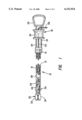
- FIG. 1 is a partially sectioned side elevation of an endoscopic bipolar biopsy forceps constructed in accordance with the present invention
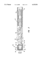
- FIG. 2 is a partially sectioned view of the distal end portion of the instrument of FIG. 1;
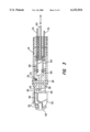
- FIG. 3 is a top plan view of the distal end portion of the instrument of FIG. 1.
- the bipolar biopsy device configured in accordance with the present invention is indicated generally by numeral 10 and comprises an elongated tubular member 12 whose outside diameter is sufficiently small to pass through the working lumen of an endoscope (not shown) where the endoscope further includes illumination fibers and image fibers traversing the length thereof permitting viewing of a surgical site.
- the elongated tubular body member 12 has a proximal end 14 affixed to a stationary portion 16 of a handle device 18.
- Slidably mounted on the stationary portion 16 of the handle 18 is a movable spool 20 adapted to slide longitudinally along guides 22 and 24.
- the stationary portion of the handle also includes a finger loop 26 at the proximal end of the guide rods 22 and 24.
- the elongated tubular member 12 also has a distal end 28 to which is attached end effectors, indicated generally by numeral 30 in FIG. 1.
- the end effectors 30 comprise a pair of jaw members including jaws 32 and 34, which are pivotally joined together by a rivet 36 that extends through aligned bores 38 and 40 in the jaw members so that the jaws 32 and 34 are free to pivot with respect to one another in a scissors-like action.
- each of the jaw members comprises a shank as at 42 and 44 having an integrally formed, conductive, cup-like receptacle 46 and 48 which may be circular in cross section and whose open ends are defined by a tapered periphery to form a sharp cutting edge, as at 50.
- tissue collecting cups 46 and 48 are coated or otherwise covered by an insulating layer 52 and 54 and a conductive electrode, as at 56 in FIG. 3, are supported atop the insulating layers 52 and 54 and lead to electrodes 58, 60 formed on the front peripheral surfaces of the jaws, electrode 58, 60 are electrically isolated from the metal cutting edge 50 by the insulating layers.
- the movable portion 20 of the handle member 18 is connected by a conductive push rod 62 to a linkage 64 that is pivotally connected to a lever member 66 that forms a part of the jaws 32 and 34.
- a linkage 64 that is pivotally connected to a lever member 66 that forms a part of the jaws 32 and 34.
- an electrosurgical generator (not shown) is connected, via a cord 68 (FIG. 1), to the instrument 10. Specifically, one of the conductors in the card attaches to the conductive push rod 62 which connects to the jaws 32 and 34.
- a second conductor 70 also extends through the lumen 13 of the elongated tubular member 12 and bifurcates near its distal end to connect to the metal traces, as at 56 and 57, leading to the electrodes 58 and 60, respectively.
- a foot switch (not shown) associated with the electrosurgical generator is closed, an electrocautery voltage is developed between the electrode 58 and conductive specimen collection cup 46 on which it is mounted. Likewise, an electrocautery voltage is established between the electrode 60 and the conductive cup 48 on which it is mounted. In that each of the cups is at the same electrical potential, no short circuiting takes place when the sharpened cutting edges 50 of each of the jaws come into contact.
- the invention described herein is somewhat easier to manufacture than is the device described in my earlier U.S. Pat. No. 5,603,711.
- the insulating material 52 applied to the outer surface of the opposed jaws 32 and 34 may be a ceramic, glass, a high temperature plastic that may be deposited through a mask to provide a desired routing pattern. It may also be molded on or otherwise bonded to the jaws.
- the conductive electrodes and the metal conductors leading to them may also be applied atop the insulative layer and then electrically connected by the wire 70 at a convenient location along the arm 42 or 44 of the jaws.
- this is achieved by providing a bore 72 through the arm 44 so that a bifurcated branch of the conductor 70 can be brought up through the bore to make electrical contact with the conductor 56 on the surface of the arm 42.
- a similar connection may be made to the electrode 57 on the arm 44 leading to the electrode 60.
- the electrode may also be prefabricated as a flexible printed circuit and subsequently bonded in place on the metal end effectors.
- the endoscopic biopsy instrument described herein differs from the prior art in that the electrocautery voltage is developed between the inner metal tissue cutting and retention cups and an electrode carried by but insulated from those cups.
Abstract
Description
Claims (4)
Priority Applications (1)
| Application Number | Priority Date | Filing Date | Title |
|---|---|---|---|
| US09/404,694 US6152924A (en) | 1999-09-24 | 1999-09-24 | Bipolar biopsy forceps |
Applications Claiming Priority (1)
| Application Number | Priority Date | Filing Date | Title |
|---|---|---|---|
| US09/404,694 US6152924A (en) | 1999-09-24 | 1999-09-24 | Bipolar biopsy forceps |
Publications (1)
| Publication Number | Publication Date |
|---|---|
| US6152924A true US6152924A (en) | 2000-11-28 |
Family
ID=23600655
Family Applications (1)
| Application Number | Title | Priority Date | Filing Date |
|---|---|---|---|
| US09/404,694 Expired - Fee Related US6152924A (en) | 1999-09-24 | 1999-09-24 | Bipolar biopsy forceps |
Country Status (1)
| Country | Link |
|---|---|
| US (1) | US6152924A (en) |
Cited By (33)
| Publication number | Priority date | Publication date | Assignee | Title |
|---|---|---|---|---|
| US20040260281A1 (en) * | 2002-09-19 | 2004-12-23 | Baxter Chester O. | Finger tip electrosurgical medical device |
| US20050043758A1 (en) * | 2003-08-18 | 2005-02-24 | Scimed Life Systems, Inc. | Endoscopic medical instrument and related methods of use |
| US20060004355A1 (en) * | 2004-07-02 | 2006-01-05 | Fridolin Anders | Medical instrument for electrosurgery |
| US20080021444A1 (en) * | 2006-07-20 | 2008-01-24 | Paul Scoption | Multifunction medical device and related methods of use |
| US20090036881A1 (en) * | 2007-07-30 | 2009-02-05 | Ryan Artale | Polyp removal jaws and method of use |
| US8147489B2 (en) | 2005-01-14 | 2012-04-03 | Covidien Ag | Open vessel sealing instrument |
| US8197633B2 (en) | 2005-09-30 | 2012-06-12 | Covidien Ag | Method for manufacturing an end effector assembly |
| US8257352B2 (en) | 2003-11-17 | 2012-09-04 | Covidien Ag | Bipolar forceps having monopolar extension |
| US8317726B2 (en) | 2005-05-13 | 2012-11-27 | Boston Scientific Scimed, Inc. | Biopsy forceps assemblies |
| US8361072B2 (en) | 2005-09-30 | 2013-01-29 | Covidien Ag | Insulating boot for electrosurgical forceps |
| US8394095B2 (en) | 2005-09-30 | 2013-03-12 | Covidien Ag | Insulating boot for electrosurgical forceps |
| US8394096B2 (en) | 2003-11-19 | 2013-03-12 | Covidien Ag | Open vessel sealing instrument with cutting mechanism |
| USD680220S1 (en) | 2012-01-12 | 2013-04-16 | Coviden IP | Slider handle for laparoscopic device |
| US8454602B2 (en) | 2009-05-07 | 2013-06-04 | Covidien Lp | Apparatus, system, and method for performing an electrosurgical procedure |
| US8523898B2 (en) | 2009-07-08 | 2013-09-03 | Covidien Lp | Endoscopic electrosurgical jaws with offset knife |
| US8551091B2 (en) | 2002-10-04 | 2013-10-08 | Covidien Ag | Vessel sealing instrument with electrical cutting mechanism |
| US8568444B2 (en) | 2008-10-03 | 2013-10-29 | Covidien Lp | Method of transferring rotational motion in an articulating surgical instrument |
| US8591506B2 (en) | 1998-10-23 | 2013-11-26 | Covidien Ag | Vessel sealing system |
| US8852228B2 (en) | 2009-01-13 | 2014-10-07 | Covidien Lp | Apparatus, system, and method for performing an electrosurgical procedure |
| US8898888B2 (en) | 2009-09-28 | 2014-12-02 | Covidien Lp | System for manufacturing electrosurgical seal plates |
| US8945125B2 (en) | 2002-11-14 | 2015-02-03 | Covidien Ag | Compressible jaw configuration with bipolar RF output electrodes for soft tissue fusion |
| US9028493B2 (en) | 2009-09-18 | 2015-05-12 | Covidien Lp | In vivo attachable and detachable end effector assembly and laparoscopic surgical instrument and methods therefor |
| US9113940B2 (en) | 2011-01-14 | 2015-08-25 | Covidien Lp | Trigger lockout and kickback mechanism for surgical instruments |
| US9113898B2 (en) | 2008-10-09 | 2015-08-25 | Covidien Lp | Apparatus, system, and method for performing an electrosurgical procedure |
| US20160089119A1 (en) * | 2014-09-25 | 2016-03-31 | Covidien Lp | Energy-based lymph node dissection device |
| US9848938B2 (en) | 2003-11-13 | 2017-12-26 | Covidien Ag | Compressible jaw configuration with bipolar RF output electrodes for soft tissue fusion |
| US9855091B2 (en) | 2014-04-02 | 2018-01-02 | Gyrus Acmi, Inc. | Surgical device having changeable elements |
| CN107736936A (en) * | 2017-11-28 | 2018-02-27 | 徐川东 | The bipolar jaw type cutting ablation knife of throat |
| US10213250B2 (en) | 2015-11-05 | 2019-02-26 | Covidien Lp | Deployment and safety mechanisms for surgical instruments |
| US20190059981A1 (en) * | 2017-08-29 | 2019-02-28 | Sea-Quan Su | Non-invasive radio-frequency ablation system |
| US10251696B2 (en) | 2001-04-06 | 2019-04-09 | Covidien Ag | Vessel sealer and divider with stop members |
| US10987159B2 (en) | 2015-08-26 | 2021-04-27 | Covidien Lp | Electrosurgical end effector assemblies and electrosurgical forceps configured to reduce thermal spread |
| US20220022941A1 (en) * | 2020-07-23 | 2022-01-27 | Covidien Lp | Devices and methods for shallow depth ablation |
Citations (3)
| Publication number | Priority date | Publication date | Assignee | Title |
|---|---|---|---|---|
| US5603723A (en) * | 1995-01-11 | 1997-02-18 | United States Surgical Corporation | Surgical instrument configured to be disassembled for cleaning |
| US5603711A (en) * | 1995-01-20 | 1997-02-18 | Everest Medical Corp. | Endoscopic bipolar biopsy forceps |
| US6039733A (en) * | 1995-09-19 | 2000-03-21 | Valleylab, Inc. | Method of vascular tissue sealing pressure control |
-
1999
- 1999-09-24 US US09/404,694 patent/US6152924A/en not_active Expired - Fee Related
Patent Citations (4)
| Publication number | Priority date | Publication date | Assignee | Title |
|---|---|---|---|---|
| US5603723A (en) * | 1995-01-11 | 1997-02-18 | United States Surgical Corporation | Surgical instrument configured to be disassembled for cleaning |
| US5603711A (en) * | 1995-01-20 | 1997-02-18 | Everest Medical Corp. | Endoscopic bipolar biopsy forceps |
| US5743906A (en) * | 1995-01-20 | 1998-04-28 | Everest Medical Corporation | Endoscopic bipolar biopsy forceps |
| US6039733A (en) * | 1995-09-19 | 2000-03-21 | Valleylab, Inc. | Method of vascular tissue sealing pressure control |
Cited By (64)
| Publication number | Priority date | Publication date | Assignee | Title |
|---|---|---|---|---|
| US8591506B2 (en) | 1998-10-23 | 2013-11-26 | Covidien Ag | Vessel sealing system |
| US9463067B2 (en) | 1998-10-23 | 2016-10-11 | Covidien Ag | Vessel sealing system |
| US9375271B2 (en) | 1998-10-23 | 2016-06-28 | Covidien Ag | Vessel sealing system |
| US9375270B2 (en) | 1998-10-23 | 2016-06-28 | Covidien Ag | Vessel sealing system |
| US10265121B2 (en) | 2001-04-06 | 2019-04-23 | Covidien Ag | Vessel sealer and divider |
| US10687887B2 (en) | 2001-04-06 | 2020-06-23 | Covidien Ag | Vessel sealer and divider |
| US10251696B2 (en) | 2001-04-06 | 2019-04-09 | Covidien Ag | Vessel sealer and divider with stop members |
| US20070093807A1 (en) * | 2002-09-19 | 2007-04-26 | Baxter Chester O Iii | Finger tip electrosurgical medical device |
| US20040260281A1 (en) * | 2002-09-19 | 2004-12-23 | Baxter Chester O. | Finger tip electrosurgical medical device |
| US8551091B2 (en) | 2002-10-04 | 2013-10-08 | Covidien Ag | Vessel sealing instrument with electrical cutting mechanism |
| US8945125B2 (en) | 2002-11-14 | 2015-02-03 | Covidien Ag | Compressible jaw configuration with bipolar RF output electrodes for soft tissue fusion |
| US7951165B2 (en) | 2003-08-18 | 2011-05-31 | Boston Scientific Scimed, Inc. | Endoscopic medical instrument and related methods of use |
| US20050043758A1 (en) * | 2003-08-18 | 2005-02-24 | Scimed Life Systems, Inc. | Endoscopic medical instrument and related methods of use |
| US9848938B2 (en) | 2003-11-13 | 2017-12-26 | Covidien Ag | Compressible jaw configuration with bipolar RF output electrodes for soft tissue fusion |
| US10441350B2 (en) | 2003-11-17 | 2019-10-15 | Covidien Ag | Bipolar forceps having monopolar extension |
| US8257352B2 (en) | 2003-11-17 | 2012-09-04 | Covidien Ag | Bipolar forceps having monopolar extension |
| US8597296B2 (en) | 2003-11-17 | 2013-12-03 | Covidien Ag | Bipolar forceps having monopolar extension |
| US8394096B2 (en) | 2003-11-19 | 2013-03-12 | Covidien Ag | Open vessel sealing instrument with cutting mechanism |
| US7553311B2 (en) * | 2004-07-02 | 2009-06-30 | Karl Storz Gmbh & Co. Kg | Medical instrument for electrosurgery |
| US20060004355A1 (en) * | 2004-07-02 | 2006-01-05 | Fridolin Anders | Medical instrument for electrosurgery |
| US8147489B2 (en) | 2005-01-14 | 2012-04-03 | Covidien Ag | Open vessel sealing instrument |
| US8317726B2 (en) | 2005-05-13 | 2012-11-27 | Boston Scientific Scimed, Inc. | Biopsy forceps assemblies |
| US8672859B2 (en) | 2005-05-13 | 2014-03-18 | Boston Scientific Scimed, Inc. | Biopsy forceps assemblies |
| US8197633B2 (en) | 2005-09-30 | 2012-06-12 | Covidien Ag | Method for manufacturing an end effector assembly |
| US8361072B2 (en) | 2005-09-30 | 2013-01-29 | Covidien Ag | Insulating boot for electrosurgical forceps |
| US8394095B2 (en) | 2005-09-30 | 2013-03-12 | Covidien Ag | Insulating boot for electrosurgical forceps |
| WO2008011251A3 (en) * | 2006-07-20 | 2008-02-28 | Boston Scient Scimed Inc | Multifunction medical device and related methods of use |
| US20080021444A1 (en) * | 2006-07-20 | 2008-01-24 | Paul Scoption | Multifunction medical device and related methods of use |
| US8226647B2 (en) | 2006-07-20 | 2012-07-24 | Boston Scientific Scimed, Inc. | Multifunction medical device and related methods of use |
| WO2008011251A2 (en) * | 2006-07-20 | 2008-01-24 | Boston Scientific Limited | Multifunction medical device and related methods of use |
| US8636735B2 (en) | 2006-07-20 | 2014-01-28 | Boston Scientific Scimed, Inc. | Multifunction medical device and related methods of use |
| US11534238B2 (en) | 2006-07-20 | 2022-12-27 | Boston Scientific Scimed, Inc. | Multifunction medical device and related methods of use |
| US20090036881A1 (en) * | 2007-07-30 | 2009-02-05 | Ryan Artale | Polyp removal jaws and method of use |
| US8568444B2 (en) | 2008-10-03 | 2013-10-29 | Covidien Lp | Method of transferring rotational motion in an articulating surgical instrument |
| US9113898B2 (en) | 2008-10-09 | 2015-08-25 | Covidien Lp | Apparatus, system, and method for performing an electrosurgical procedure |
| US8852228B2 (en) | 2009-01-13 | 2014-10-07 | Covidien Lp | Apparatus, system, and method for performing an electrosurgical procedure |
| US9655674B2 (en) | 2009-01-13 | 2017-05-23 | Covidien Lp | Apparatus, system and method for performing an electrosurgical procedure |
| US9345535B2 (en) | 2009-05-07 | 2016-05-24 | Covidien Lp | Apparatus, system and method for performing an electrosurgical procedure |
| US8454602B2 (en) | 2009-05-07 | 2013-06-04 | Covidien Lp | Apparatus, system, and method for performing an electrosurgical procedure |
| US8858554B2 (en) | 2009-05-07 | 2014-10-14 | Covidien Lp | Apparatus, system, and method for performing an electrosurgical procedure |
| US10085794B2 (en) | 2009-05-07 | 2018-10-02 | Covidien Lp | Apparatus, system and method for performing an electrosurgical procedure |
| US8523898B2 (en) | 2009-07-08 | 2013-09-03 | Covidien Lp | Endoscopic electrosurgical jaws with offset knife |
| US9028493B2 (en) | 2009-09-18 | 2015-05-12 | Covidien Lp | In vivo attachable and detachable end effector assembly and laparoscopic surgical instrument and methods therefor |
| US9931131B2 (en) | 2009-09-18 | 2018-04-03 | Covidien Lp | In vivo attachable and detachable end effector assembly and laparoscopic surgical instrument and methods therefor |
| US11490955B2 (en) | 2009-09-28 | 2022-11-08 | Covidien Lp | Electrosurgical seal plates |
| US9750561B2 (en) | 2009-09-28 | 2017-09-05 | Covidien Lp | System for manufacturing electrosurgical seal plates |
| US10188454B2 (en) | 2009-09-28 | 2019-01-29 | Covidien Lp | System for manufacturing electrosurgical seal plates |
| US11026741B2 (en) | 2009-09-28 | 2021-06-08 | Covidien Lp | Electrosurgical seal plates |
| US9265552B2 (en) | 2009-09-28 | 2016-02-23 | Covidien Lp | Method of manufacturing electrosurgical seal plates |
| US8898888B2 (en) | 2009-09-28 | 2014-12-02 | Covidien Lp | System for manufacturing electrosurgical seal plates |
| US11660108B2 (en) | 2011-01-14 | 2023-05-30 | Covidien Lp | Trigger lockout and kickback mechanism for surgical instruments |
| US10383649B2 (en) | 2011-01-14 | 2019-08-20 | Covidien Lp | Trigger lockout and kickback mechanism for surgical instruments |
| US9113940B2 (en) | 2011-01-14 | 2015-08-25 | Covidien Lp | Trigger lockout and kickback mechanism for surgical instruments |
| USD680220S1 (en) | 2012-01-12 | 2013-04-16 | Coviden IP | Slider handle for laparoscopic device |
| US9855091B2 (en) | 2014-04-02 | 2018-01-02 | Gyrus Acmi, Inc. | Surgical device having changeable elements |
| US10702331B2 (en) | 2014-04-02 | 2020-07-07 | Gyrus Acmi, Inc. | Surgical device having changeable elements |
| US20160089119A1 (en) * | 2014-09-25 | 2016-03-31 | Covidien Lp | Energy-based lymph node dissection device |
| US10987159B2 (en) | 2015-08-26 | 2021-04-27 | Covidien Lp | Electrosurgical end effector assemblies and electrosurgical forceps configured to reduce thermal spread |
| US10213250B2 (en) | 2015-11-05 | 2019-02-26 | Covidien Lp | Deployment and safety mechanisms for surgical instruments |
| US10813682B2 (en) * | 2017-08-29 | 2020-10-27 | Sea-Quan Su | Non-invasive radio-frequency ablation system |
| US20190059978A1 (en) * | 2017-08-29 | 2019-02-28 | Sea-Quan Su | Non-invasive radio-frequency ablation system |
| US20190059981A1 (en) * | 2017-08-29 | 2019-02-28 | Sea-Quan Su | Non-invasive radio-frequency ablation system |
| CN107736936A (en) * | 2017-11-28 | 2018-02-27 | 徐川东 | The bipolar jaw type cutting ablation knife of throat |
| US20220022941A1 (en) * | 2020-07-23 | 2022-01-27 | Covidien Lp | Devices and methods for shallow depth ablation |
Similar Documents
| Publication | Publication Date | Title |
|---|---|---|
| US6152924A (en) | Bipolar biopsy forceps | |
| US5603711A (en) | Endoscopic bipolar biopsy forceps | |
| JP3839491B2 (en) | Bipolar multiple sample biopsy forceps | |
| US5908420A (en) | Surgical scissors with bipolar distal electrodes | |
| AU707821B2 (en) | Bipolar cutting and coagulation device | |
| US6334860B1 (en) | Bipolar medical instrument | |
| WO1997024995A9 (en) | Endoscopic bipolar multiple sample bioptome | |
| US5342381A (en) | Combination bipolar scissors and forceps instrument | |
| JP3150157B2 (en) | Biopsy forceps for removing a sample of tissue and optionally coagulating blood | |
| US6190386B1 (en) | Electrosurgical forceps with needle electrodes | |
| US5891141A (en) | Bipolar electrosurgical instrument for cutting and sealing tubular tissue structures | |
| JP3384750B2 (en) | High frequency treatment tool | |
| US6743230B2 (en) | Bipolar grasping instrument | |
| US7204835B2 (en) | Surgical instrument | |
| US6562035B1 (en) | Insulated surgical scissors including cauterizing tip | |
| US20040006340A1 (en) | Bipolar electrosurgical instrument for cutting, desiccating and sealing tissue | |
| EP0572131A1 (en) | Surgical scissors with bipolar coagulation feature | |
| EP0635244A1 (en) | Bipolar electrosurgical scissors having nonlinear blades | |
| US20040049185A1 (en) | Bipolar electrosurgical instrument for cutting desiccating and sealing tissue | |
| US20100292690A1 (en) | Surgical apparatus for tissue sealing and cutting | |
| WO2009112802A1 (en) | Surgical instrument | |
| WO1994008524A1 (en) | Electrosurgical instruments having a detachable working end | |
| JPH05154156A (en) | Biopsy device equipped with coagulation capability by double-pole | |
| EP1691705A1 (en) | A surgical instrument | |
| JPH11137562A (en) | Surgical electric cutting apparatus |
Legal Events
| Date | Code | Title | Description |
|---|---|---|---|
| AS | Assignment |
Owner name: EVEREST MEDICAL CORPORATION, MINNESOTA Free format text: ASSIGNMENT OF ASSIGNORS INTEREST;ASSIGNOR:PARINS, DAVID J.;REEL/FRAME:010293/0210 Effective date: 19990920 |
|
| AS | Assignment |
Owner name: GYRUS MEDICAL, INC., MINNESOTA Free format text: CHANGE OF NAME;ASSIGNOR:EVEREST MEDICAL CORPORATION;REEL/FRAME:012802/0936 Effective date: 20010405 |
|
| REMI | Maintenance fee reminder mailed | ||
| LAPS | Lapse for failure to pay maintenance fees | ||
| STCH | Information on status: patent discontinuation |
Free format text: PATENT EXPIRED DUE TO NONPAYMENT OF MAINTENANCE FEES UNDER 37 CFR 1.362 |
|
| FP | Lapsed due to failure to pay maintenance fee |
Effective date: 20041128 |