US6152961A - Acetabular prosthesis assembly - Google Patents
Acetabular prosthesis assembly Download PDFInfo
- Publication number
- US6152961A US6152961A US08/998,881 US99888197A US6152961A US 6152961 A US6152961 A US 6152961A US 99888197 A US99888197 A US 99888197A US 6152961 A US6152961 A US 6152961A
- Authority
- US
- United States
- Prior art keywords
- liner
- prosthesis
- shell
- component
- groove
- Prior art date
- Legal status (The legal status is an assumption and is not a legal conclusion. Google has not performed a legal analysis and makes no representation as to the accuracy of the status listed.)
- Expired - Lifetime
Links
Images

Classifications
-
- A—HUMAN NECESSITIES
- A61—MEDICAL OR VETERINARY SCIENCE; HYGIENE
- A61F—FILTERS IMPLANTABLE INTO BLOOD VESSELS; PROSTHESES; DEVICES PROVIDING PATENCY TO, OR PREVENTING COLLAPSING OF, TUBULAR STRUCTURES OF THE BODY, e.g. STENTS; ORTHOPAEDIC, NURSING OR CONTRACEPTIVE DEVICES; FOMENTATION; TREATMENT OR PROTECTION OF EYES OR EARS; BANDAGES, DRESSINGS OR ABSORBENT PADS; FIRST-AID KITS
- A61F2/00—Filters implantable into blood vessels; Prostheses, i.e. artificial substitutes or replacements for parts of the body; Appliances for connecting them with the body; Devices providing patency to, or preventing collapsing of, tubular structures of the body, e.g. stents
- A61F2/02—Prostheses implantable into the body
- A61F2/30—Joints
- A61F2/32—Joints for the hip
- A61F2/34—Acetabular cups
-
- A—HUMAN NECESSITIES
- A61—MEDICAL OR VETERINARY SCIENCE; HYGIENE
- A61F—FILTERS IMPLANTABLE INTO BLOOD VESSELS; PROSTHESES; DEVICES PROVIDING PATENCY TO, OR PREVENTING COLLAPSING OF, TUBULAR STRUCTURES OF THE BODY, e.g. STENTS; ORTHOPAEDIC, NURSING OR CONTRACEPTIVE DEVICES; FOMENTATION; TREATMENT OR PROTECTION OF EYES OR EARS; BANDAGES, DRESSINGS OR ABSORBENT PADS; FIRST-AID KITS
- A61F2/00—Filters implantable into blood vessels; Prostheses, i.e. artificial substitutes or replacements for parts of the body; Appliances for connecting them with the body; Devices providing patency to, or preventing collapsing of, tubular structures of the body, e.g. stents
- A61F2/02—Prostheses implantable into the body
- A61F2/30—Joints
- A61F2002/30001—Additional features of subject-matter classified in A61F2/28, A61F2/30 and subgroups thereof
- A61F2002/30316—The prosthesis having different structural features at different locations within the same prosthesis; Connections between prosthetic parts; Special structural features of bone or joint prostheses not otherwise provided for
- A61F2002/30329—Connections or couplings between prosthetic parts, e.g. between modular parts; Connecting elements
- A61F2002/30331—Connections or couplings between prosthetic parts, e.g. between modular parts; Connecting elements made by longitudinally pushing a protrusion into a complementarily-shaped recess, e.g. held by friction fit
- A61F2002/30362—Connections or couplings between prosthetic parts, e.g. between modular parts; Connecting elements made by longitudinally pushing a protrusion into a complementarily-shaped recess, e.g. held by friction fit with possibility of relative movement between the protrusion and the recess
- A61F2002/30364—Rotation about the common longitudinal axis
- A61F2002/30367—Rotation about the common longitudinal axis with additional means for preventing said rotation
-
- A—HUMAN NECESSITIES
- A61—MEDICAL OR VETERINARY SCIENCE; HYGIENE
- A61F—FILTERS IMPLANTABLE INTO BLOOD VESSELS; PROSTHESES; DEVICES PROVIDING PATENCY TO, OR PREVENTING COLLAPSING OF, TUBULAR STRUCTURES OF THE BODY, e.g. STENTS; ORTHOPAEDIC, NURSING OR CONTRACEPTIVE DEVICES; FOMENTATION; TREATMENT OR PROTECTION OF EYES OR EARS; BANDAGES, DRESSINGS OR ABSORBENT PADS; FIRST-AID KITS
- A61F2/00—Filters implantable into blood vessels; Prostheses, i.e. artificial substitutes or replacements for parts of the body; Appliances for connecting them with the body; Devices providing patency to, or preventing collapsing of, tubular structures of the body, e.g. stents
- A61F2/02—Prostheses implantable into the body
- A61F2/30—Joints
- A61F2002/30001—Additional features of subject-matter classified in A61F2/28, A61F2/30 and subgroups thereof
- A61F2002/30316—The prosthesis having different structural features at different locations within the same prosthesis; Connections between prosthetic parts; Special structural features of bone or joint prostheses not otherwise provided for
- A61F2002/30329—Connections or couplings between prosthetic parts, e.g. between modular parts; Connecting elements
- A61F2002/30383—Connections or couplings between prosthetic parts, e.g. between modular parts; Connecting elements made by laterally inserting a protrusion, e.g. a rib into a complementarily-shaped groove
- A61F2002/30403—Longitudinally-oriented cooperating ribs and grooves on mating lateral surfaces of a mainly longitudinal connection
-
- A—HUMAN NECESSITIES
- A61—MEDICAL OR VETERINARY SCIENCE; HYGIENE
- A61F—FILTERS IMPLANTABLE INTO BLOOD VESSELS; PROSTHESES; DEVICES PROVIDING PATENCY TO, OR PREVENTING COLLAPSING OF, TUBULAR STRUCTURES OF THE BODY, e.g. STENTS; ORTHOPAEDIC, NURSING OR CONTRACEPTIVE DEVICES; FOMENTATION; TREATMENT OR PROTECTION OF EYES OR EARS; BANDAGES, DRESSINGS OR ABSORBENT PADS; FIRST-AID KITS
- A61F2/00—Filters implantable into blood vessels; Prostheses, i.e. artificial substitutes or replacements for parts of the body; Appliances for connecting them with the body; Devices providing patency to, or preventing collapsing of, tubular structures of the body, e.g. stents
- A61F2/02—Prostheses implantable into the body
- A61F2/30—Joints
- A61F2002/30001—Additional features of subject-matter classified in A61F2/28, A61F2/30 and subgroups thereof
- A61F2002/30316—The prosthesis having different structural features at different locations within the same prosthesis; Connections between prosthetic parts; Special structural features of bone or joint prostheses not otherwise provided for
- A61F2002/30329—Connections or couplings between prosthetic parts, e.g. between modular parts; Connecting elements
- A61F2002/30476—Connections or couplings between prosthetic parts, e.g. between modular parts; Connecting elements locked by an additional locking mechanism
- A61F2002/30487—Circumferential cooperating grooves and beads on cooperating lateral surfaces of a mainly longitudinal connection
-
- A—HUMAN NECESSITIES
- A61—MEDICAL OR VETERINARY SCIENCE; HYGIENE
- A61F—FILTERS IMPLANTABLE INTO BLOOD VESSELS; PROSTHESES; DEVICES PROVIDING PATENCY TO, OR PREVENTING COLLAPSING OF, TUBULAR STRUCTURES OF THE BODY, e.g. STENTS; ORTHOPAEDIC, NURSING OR CONTRACEPTIVE DEVICES; FOMENTATION; TREATMENT OR PROTECTION OF EYES OR EARS; BANDAGES, DRESSINGS OR ABSORBENT PADS; FIRST-AID KITS
- A61F2/00—Filters implantable into blood vessels; Prostheses, i.e. artificial substitutes or replacements for parts of the body; Appliances for connecting them with the body; Devices providing patency to, or preventing collapsing of, tubular structures of the body, e.g. stents
- A61F2/02—Prostheses implantable into the body
- A61F2/30—Joints
- A61F2002/30001—Additional features of subject-matter classified in A61F2/28, A61F2/30 and subgroups thereof
- A61F2002/30316—The prosthesis having different structural features at different locations within the same prosthesis; Connections between prosthetic parts; Special structural features of bone or joint prostheses not otherwise provided for
- A61F2002/30329—Connections or couplings between prosthetic parts, e.g. between modular parts; Connecting elements
- A61F2002/30476—Connections or couplings between prosthetic parts, e.g. between modular parts; Connecting elements locked by an additional locking mechanism
- A61F2002/305—Snap connection
-
- A—HUMAN NECESSITIES
- A61—MEDICAL OR VETERINARY SCIENCE; HYGIENE
- A61F—FILTERS IMPLANTABLE INTO BLOOD VESSELS; PROSTHESES; DEVICES PROVIDING PATENCY TO, OR PREVENTING COLLAPSING OF, TUBULAR STRUCTURES OF THE BODY, e.g. STENTS; ORTHOPAEDIC, NURSING OR CONTRACEPTIVE DEVICES; FOMENTATION; TREATMENT OR PROTECTION OF EYES OR EARS; BANDAGES, DRESSINGS OR ABSORBENT PADS; FIRST-AID KITS
- A61F2/00—Filters implantable into blood vessels; Prostheses, i.e. artificial substitutes or replacements for parts of the body; Appliances for connecting them with the body; Devices providing patency to, or preventing collapsing of, tubular structures of the body, e.g. stents
- A61F2/02—Prostheses implantable into the body
- A61F2/30—Joints
- A61F2002/30001—Additional features of subject-matter classified in A61F2/28, A61F2/30 and subgroups thereof
- A61F2002/30316—The prosthesis having different structural features at different locations within the same prosthesis; Connections between prosthetic parts; Special structural features of bone or joint prostheses not otherwise provided for
- A61F2002/30535—Special structural features of bone or joint prostheses not otherwise provided for
- A61F2002/30537—Special structural features of bone or joint prostheses not otherwise provided for adjustable
- A61F2002/30538—Special structural features of bone or joint prostheses not otherwise provided for adjustable for adjusting angular orientation
- A61F2002/3054—Special structural features of bone or joint prostheses not otherwise provided for adjustable for adjusting angular orientation about a connection axis or implantation axis for selecting any one of a plurality of radial orientations between two modular parts, e.g. Morse taper connections, at discrete positions, angular positions or continuous positions
-
- A—HUMAN NECESSITIES
- A61—MEDICAL OR VETERINARY SCIENCE; HYGIENE
- A61F—FILTERS IMPLANTABLE INTO BLOOD VESSELS; PROSTHESES; DEVICES PROVIDING PATENCY TO, OR PREVENTING COLLAPSING OF, TUBULAR STRUCTURES OF THE BODY, e.g. STENTS; ORTHOPAEDIC, NURSING OR CONTRACEPTIVE DEVICES; FOMENTATION; TREATMENT OR PROTECTION OF EYES OR EARS; BANDAGES, DRESSINGS OR ABSORBENT PADS; FIRST-AID KITS
- A61F2/00—Filters implantable into blood vessels; Prostheses, i.e. artificial substitutes or replacements for parts of the body; Appliances for connecting them with the body; Devices providing patency to, or preventing collapsing of, tubular structures of the body, e.g. stents
- A61F2/02—Prostheses implantable into the body
- A61F2/30—Joints
- A61F2/30767—Special external or bone-contacting surface, e.g. coating for improving bone ingrowth
- A61F2/30771—Special external or bone-contacting surface, e.g. coating for improving bone ingrowth applied in original prostheses, e.g. holes or grooves
- A61F2002/30904—Special external or bone-contacting surface, e.g. coating for improving bone ingrowth applied in original prostheses, e.g. holes or grooves serrated profile, i.e. saw-toothed
-
- A—HUMAN NECESSITIES
- A61—MEDICAL OR VETERINARY SCIENCE; HYGIENE
- A61F—FILTERS IMPLANTABLE INTO BLOOD VESSELS; PROSTHESES; DEVICES PROVIDING PATENCY TO, OR PREVENTING COLLAPSING OF, TUBULAR STRUCTURES OF THE BODY, e.g. STENTS; ORTHOPAEDIC, NURSING OR CONTRACEPTIVE DEVICES; FOMENTATION; TREATMENT OR PROTECTION OF EYES OR EARS; BANDAGES, DRESSINGS OR ABSORBENT PADS; FIRST-AID KITS
- A61F2/00—Filters implantable into blood vessels; Prostheses, i.e. artificial substitutes or replacements for parts of the body; Appliances for connecting them with the body; Devices providing patency to, or preventing collapsing of, tubular structures of the body, e.g. stents
- A61F2/02—Prostheses implantable into the body
- A61F2/30—Joints
- A61F2/32—Joints for the hip
- A61F2/34—Acetabular cups
- A61F2002/3401—Acetabular cups with radial apertures, e.g. radial bores for receiving fixation screws
- A61F2002/3403—Polar aperture
-
- A—HUMAN NECESSITIES
- A61—MEDICAL OR VETERINARY SCIENCE; HYGIENE
- A61F—FILTERS IMPLANTABLE INTO BLOOD VESSELS; PROSTHESES; DEVICES PROVIDING PATENCY TO, OR PREVENTING COLLAPSING OF, TUBULAR STRUCTURES OF THE BODY, e.g. STENTS; ORTHOPAEDIC, NURSING OR CONTRACEPTIVE DEVICES; FOMENTATION; TREATMENT OR PROTECTION OF EYES OR EARS; BANDAGES, DRESSINGS OR ABSORBENT PADS; FIRST-AID KITS
- A61F2/00—Filters implantable into blood vessels; Prostheses, i.e. artificial substitutes or replacements for parts of the body; Appliances for connecting them with the body; Devices providing patency to, or preventing collapsing of, tubular structures of the body, e.g. stents
- A61F2/02—Prostheses implantable into the body
- A61F2/30—Joints
- A61F2/32—Joints for the hip
- A61F2/34—Acetabular cups
- A61F2002/3412—Acetabular cups with pins or protrusions, e.g. non-sharp pins or protrusions projecting from a shell surface
- A61F2002/342—Acetabular cups with pins or protrusions, e.g. non-sharp pins or protrusions projecting from a shell surface the outer shell having circumferential protrusions parallel to the equatorial plane, e.g. circumferential fins or wings
-
- A—HUMAN NECESSITIES
- A61—MEDICAL OR VETERINARY SCIENCE; HYGIENE
- A61F—FILTERS IMPLANTABLE INTO BLOOD VESSELS; PROSTHESES; DEVICES PROVIDING PATENCY TO, OR PREVENTING COLLAPSING OF, TUBULAR STRUCTURES OF THE BODY, e.g. STENTS; ORTHOPAEDIC, NURSING OR CONTRACEPTIVE DEVICES; FOMENTATION; TREATMENT OR PROTECTION OF EYES OR EARS; BANDAGES, DRESSINGS OR ABSORBENT PADS; FIRST-AID KITS
- A61F2/00—Filters implantable into blood vessels; Prostheses, i.e. artificial substitutes or replacements for parts of the body; Appliances for connecting them with the body; Devices providing patency to, or preventing collapsing of, tubular structures of the body, e.g. stents
- A61F2/02—Prostheses implantable into the body
- A61F2/30—Joints
- A61F2/32—Joints for the hip
- A61F2/34—Acetabular cups
- A61F2002/348—Additional features
- A61F2002/3482—Two hemispherical halves having completely different structures
-
- A—HUMAN NECESSITIES
- A61—MEDICAL OR VETERINARY SCIENCE; HYGIENE
- A61F—FILTERS IMPLANTABLE INTO BLOOD VESSELS; PROSTHESES; DEVICES PROVIDING PATENCY TO, OR PREVENTING COLLAPSING OF, TUBULAR STRUCTURES OF THE BODY, e.g. STENTS; ORTHOPAEDIC, NURSING OR CONTRACEPTIVE DEVICES; FOMENTATION; TREATMENT OR PROTECTION OF EYES OR EARS; BANDAGES, DRESSINGS OR ABSORBENT PADS; FIRST-AID KITS
- A61F2220/00—Fixations or connections for prostheses classified in groups A61F2/00 - A61F2/26 or A61F2/82 or A61F9/00 or A61F11/00 or subgroups thereof
- A61F2220/0025—Connections or couplings between prosthetic parts, e.g. between modular parts; Connecting elements
- A61F2220/0033—Connections or couplings between prosthetic parts, e.g. between modular parts; Connecting elements made by longitudinally pushing a protrusion into a complementary-shaped recess, e.g. held by friction fit
-
- A—HUMAN NECESSITIES
- A61—MEDICAL OR VETERINARY SCIENCE; HYGIENE
- A61F—FILTERS IMPLANTABLE INTO BLOOD VESSELS; PROSTHESES; DEVICES PROVIDING PATENCY TO, OR PREVENTING COLLAPSING OF, TUBULAR STRUCTURES OF THE BODY, e.g. STENTS; ORTHOPAEDIC, NURSING OR CONTRACEPTIVE DEVICES; FOMENTATION; TREATMENT OR PROTECTION OF EYES OR EARS; BANDAGES, DRESSINGS OR ABSORBENT PADS; FIRST-AID KITS
- A61F2310/00—Prostheses classified in A61F2/28 or A61F2/30 - A61F2/44 being constructed from or coated with a particular material
- A61F2310/00005—The prosthesis being constructed from a particular material
- A61F2310/00011—Metals or alloys
Definitions
- the invention relates to joint prostheses and more particularly to acetabular prostheses useful for partial or total replacement of the hip joint.
- Acetabular prostheses are known for use as a component for a total hip prosthesis.
- Acetabular prostheses typically include two separate components, one of which is a cup or shell that is affixed within a cavity reamed in healthy bone of the acetabulum.
- the acetabular cup may have an external (i.e., bone-contacting) geometry that is appropriate for a given patient.
- the inner geometry of the acetabular cup is usually characterized by a smooth, generally spherical cavity.
- the acetabular cup is typically made of a metal or metal alloy. In some cases, however, polymeric acetabular cups are utilized.
- a liner component is often mated with the inner geometry of the acetabular cup to provide a low friction bearing surface that articulates with a femoral head.
- the liner may have an outer, spherical surface that is of a size and shape to enable it to mate with the inner surface of the acetabular cup.
- the inner surface of the liner likewise is hemispherically shaped, having a smooth, low friction surface.
- the femoral head seats within and articulates with the internal surface of the liner.
- Acetabular cups are often made from a metal or metal alloy. Some designs, however, utilize polymeric cups.
- One polymer commonly used to form the liner is ultrahigh molecular weight polyethylene. However, it is also possible to fabricate the liner from other materials, including metals, metal alloys and ceramics.
- the acetabular cup and liner must be joined together, usually during the course of a surgical procedure. That is, a surgeon first implants the acetabular cup within the patient's acetabulum. Thereafter, the liner is separately affixed within the acetabular cup. A variety of liner designs exist and many are not symmetrical. Thus, the surgeon must determine the appropriate orientation of the liner with respect to the cup. Once the liner is properly oriented, it must remain so after affixation to the cup.
- Some acetabular prosthesis designs do not permit easy mating of the liner to the cup; the mating of some designs can, in fact, be quite challenging. Specialized tools or separate components may be necessary to join these components or to permanently affix them together. These additional steps may render the attachment process more time-consuming and may introduce the possibility that the liner and the shell will become misaligned due to surgical technique or for other reasons. Further, there is always a possibility that the joinder mechanism may fail to achieve its objective to secure the two components to one another.
- An acetabular prosthesis has a shell component that is implantable within bone and a liner component that is matable to the shell.
- the shell has a generally convex bone engaging outer surface and a generally concave inner surface.
- a groove is formed in the inner surface of the shell and extends about at least a portion of the inner circumference of the shell.
- the liner which has a polar region and an equator region, has an inner concave surface and an outer, convex surface with a shape complementary to and matable within the inner surface of the shell.
- One or more positive surface feature is formed on the outer surface of the liner, adapted for selective mating with the groove of the shell.
- the liner may be joined to the shell by press fitting the two components together such that the positive surface features engage the groove.
- the prosthesis may also have a structure to prevent rotation of the liner with respect to the shell after joinder of the two components.
- the anti-rotation mechanism may be in the form of one or more tabs in the outer surface of the liner, adjacent to the positive surface features. At least one recess is formed in the shell with a size and shape complementary to the tabs such that each tab is matable within one of the recesses.
- One advantage of the prosthesis of the present invention lies in its ease of assembly and its ability to provide good attachment strength between the liner and the shell.
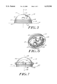
- FIG. 1 is a bottom, perspective view of an acetabular prosthesis according to the present invention.
- FIG. 2 is a bottom view of the acetabular prosthesis shown in FIG. 1.
- FIG. 3 is an elevated sectional view of the prosthesis shown in FIG. 2, at lines 3--3.
- FIG. 4 is a detailed view of portion A of the prosthesis shown in FIG. 3.
- FIG. 5 is an elevated view of a shell component useful with the acetabular prosthesis of the invention.
- FIG. 6 is a perspective view of the shell component of FIG. 5.
- FIG. 7 is an elevated view of a liner component useful with the acetabular prosthesis of the invention.
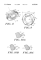
- FIG. 8 is a perspective view of another liner component useful with the acetabular prosthesis of the present invention.
- FIG. 9 is a bottom view of the liner component shown in FIG. 8.
- FIG. 10A is a detailed sectional view of a portion of a liner constructed according to one embodiment of the present invention.
- FIG. 10B is a detailed sectional view of a portion of a liner constructed according to another embodiment of the present invention.
- FIG. 10C is a detailed sectional view of a portion of a liner constructed according to another embodiment of the invention.
- the present invention provides an acetabular prosthesis with an effective and convenient mechanism for joining and securing the acetabular shell and liner components to each other.
- the acetabular prosthesis 10 includes an acetabular shell 12 and a liner 14 which are selectively attachable to one another through an interlocking engagement.
- the acetabular shell 12, illustrated in FIGS. 5 and 6, is a substantially hemispherical member having a generally convex outer bone-engaging surface 16. Opposite the outer surface 16 is a generally hemispherical, substantially concave liner surface 18.
- the shell may be characterized as having an equator region 15 and a polar region 17. Further, the shell includes an equatorial axis 19 and a polar axis 21.
- the outer surface 16, as shown in FIGS. 5 and 6, may include an apical hole 20 for seating a bone screw, and one or more additional holes 22 extending therethrough.
- the outer surface of the shell may further include surface features 24, such as ridges 26, to optimize fixation to bone and/or to encourage bone ingrowth.
- ridges 26 are the only surface features illustrated, one of ordinary skill in the art will readily appreciate that a variety of additional surface features can be formed on the outer surface to optimize performance of the prosthesis.
- the inner surface 18, as shown in FIGS. 1 through 4 and 6, includes a groove 28 that extends substantially parallel to the equatorial axis 19.
- the groove 28 may be continuous or it may be formed of discrete elements. Further, the groove 28 may extend partially or entirely around the circumference of the shell, either continuously or in discrete sections. In the embodiment illustrated in FIGS. 3 and 6, the groove 28 is disposed in the equatorial region 15, and is spaced from the rim 32 of the shell, in the direction towards the polar region 17. Further, the embodiment of FIG. 6 illustrates that the groove 28 is interrupted by recesses 30, which extend perpendicular to the equatorial axis 19.
- the groove 28 begins a distance of about 0.5 to 10 mm from the rim 32, in the direction towards the polar region 17.
- the dimensions of the groove will vary depending upon variables such as the dimensions of the shell, the dimensions of the liner and the dimensions of certain surface features present on the liner. In one embodiment, however, the groove 28 has a height 34 in the range of about 1 to 3 mm and a depth 36 of about 0.2 to 1.5 mm.
- the grooves may be separated from each other by about 0° to 180°, with 0° separation representing a continuous groove.
- the recesses 30 are intended to seat anti-rotation tabs 38 present on the liner 14, as discussed below, to prevent rotation of the liner 14 relative to the acetabular shell 12.
- the recesses 30 extend from the rim 32 towards the pole region 17.
- the height 40 of the recesses may be about 2 to 8 mm while their width 42 is about 1 to 3 mm.
- the depth 39 of the recesses may be in the range of about 0.5 to 4 mm.
- the shell 12 can be made from a variety of suitable materials. Generally, however, it is made from metals or metal alloys known to those having ordinary skill in the art.
- the liner 14 has an equatorial region 41 and a rim 45. Opposite the equator region 41 is a polar region 43. An equatorial axis 47 of the liner extends parallel to the equatorial region 41 while a polar axis 49 extends perpendicular to the equatorial axis 47.
- the liner also has a convex outer surface 44, which is substantially hemispherically shaped and complementary to inner surface 18 of shell 12.
- the liner 14 also has a concave inner surface 46 which is intended to seat a femoral head of a hip prosthesis (not shown).
- the inner surface 46 should be a smooth, low friction surface.
- the tabs 38 can be of virtually any shape that is complementary to and matable within the recesses 30 of the shell 12. Accordingly, the tabs 38 protrude from the outer surface of the liner by about 0.5 to 4 mm and have a width in the range of about 1 to 3 mm.
- Tabs 38 may be positioned at virtually any location on the outer surface 44 of the liner 14. In one embodiment, the tabs 38 are positioned adjacent to the equatorial region 41, spaced approximately 0.5 to 1.0 from the rim 45 in the direction towards the polar region 43.
- the anti-rotation tabs 38 cooperate with the recesses 30 to prevent rotation of the liner 14 relative to the shell 12.
- No specific number of anti-rotation tabs 38 and recesses 30 is necessary to prevent rotation of the liner 14 relative to the shell 12 since any number will accomplish this objective.
- more than one anti-rotation tab 38 is present and from four to nine anti-rotation tabs can be used, depending upon the size of the liner and the shell.
- the outer surface 44 of the liner 14 also includes a raised ridge 50.
- the ridge cooperates with the groove 28 to selectively attach the liner to the shell.
- the ridge protrudes from the outer surface 44 of the liner 14 by a distance sufficient to prevent noninterfering insertion of the liner 14 within the shell 12. That is, the outer diameter 51 of the liner, measured at the ridge 50, is greater than the inner diameter 52 of the opening 54 of the shell.
- the ridge 50 should protrude from the outer surface 18 of the liner by a distance in the range of about 0.1 to 1.0 mm, and preferably about 0.1 to 0.6 mm. Similarly, the outer diameter 51 of the liner measured at the ridge 50 should exceed the inner diameter 52 of the opening 54 by about 0.1 to 1.5 mm.
- the ridge 50 may be a continuous structure, or it may be present on the outer surface of the liner in discrete sections. Further, the ridge 50 may extend partially or completely about the circumference of the liner, either continuously or in discrete sections.
- the ridge 50 may take on a variety of shapes. As shown in FIGS. 10A-10C, the ridge is comprised of a superior wall 56, an inferior wall 58 and an end wall 62.
- the end wall 62 is generally parallel to the polar axis 49 of the liner as shown in FIG. 10A, or it may conform in shape to the curvature of the outer surface 44 of the liner. Moreover, the end wall 62 may be spaced apart from the outer surface 44 of the liner by about 0.1 to 0.6 mm.
- the superior wall 56 may be parallel to the equatorial axis 47 of the liner (FIG. 10A), or it can be angled with respect to the equatorial axis 47 of the liner (FIG. 10B).
- the superior wall 56 forms a downwardly sloping, acute angle ( ⁇ ) with a line drawn parallel to the equatorial axis 47.
- the range of angle (a) may be about 0 to 45 degrees.
- the inferior wall 60 may extend parallel to the equatorial axis 47 (FIG. 10A), or it may be angled with respect to the equatorial axis (FIG. 10C).
- the ridge 50 may be present in numerous alternative geometries without departing from the scope of the invention.
- the invention provides a reliable and convenient attachment mechanism for selectively joining an acetabular shell to a liner component.
- the anti-rotation tabs 38 of the liner 14 are aligned with the recesses 30 of the shell 12. This orientation allows the outer surface of the liner to be inserted through opening 54 into the inner surface of the shell 12.
- a superior edge 56 of the ridge 50 will encounter the inferior wall 58 of rim 32, preventing further insertion of the liner within the shell.
- This resistance to further insertion can be overcome by applying additional force to the liner, enabling the force fitting of the ridge 50 within the opening 54.
- the force fitting can be accomplished by expansion of the opening, slight deformation of the ridge, or by contraction of the liner. Once the initial resistance to further insertion is overcome, further force will cause the ridge 50 to be seated within groove 28 enabling the liner to be mechanically engaged within the shell.
Abstract
Description
Claims (18)
Priority Applications (5)
| Application Number | Priority Date | Filing Date | Title |
|---|---|---|---|
| US08/998,881 US6152961A (en) | 1997-12-29 | 1997-12-29 | Acetabular prosthesis assembly |
| DE69820581T DE69820581T2 (en) | 1997-12-29 | 1998-12-24 | Acetabular prosthesis kit |
| EP98310726A EP0927547B1 (en) | 1997-12-29 | 1998-12-24 | Acetabular prosthesis assembly |
| JP37738798A JP4104758B2 (en) | 1997-12-29 | 1998-12-28 | Acetabular prosthesis assembly |
| BR9805808-8A BR9805808A (en) | 1997-12-29 | 1998-12-29 | Acetabular prosthesis set |
Applications Claiming Priority (1)
| Application Number | Priority Date | Filing Date | Title |
|---|---|---|---|
| US08/998,881 US6152961A (en) | 1997-12-29 | 1997-12-29 | Acetabular prosthesis assembly |
Publications (1)
| Publication Number | Publication Date |
|---|---|
| US6152961A true US6152961A (en) | 2000-11-28 |
Family
ID=25545641
Family Applications (1)
| Application Number | Title | Priority Date | Filing Date |
|---|---|---|---|
| US08/998,881 Expired - Lifetime US6152961A (en) | 1997-12-29 | 1997-12-29 | Acetabular prosthesis assembly |
Country Status (5)
| Country | Link |
|---|---|
| US (1) | US6152961A (en) |
| EP (1) | EP0927547B1 (en) |
| JP (1) | JP4104758B2 (en) |
| BR (1) | BR9805808A (en) |
| DE (1) | DE69820581T2 (en) |
Cited By (41)
| Publication number | Priority date | Publication date | Assignee | Title |
|---|---|---|---|---|
| US20030105529A1 (en) * | 2001-11-16 | 2003-06-05 | Synder Duane G. | Prosthetic cup assembly having increased assembly congruency |
| US20040117029A1 (en) * | 2002-12-13 | 2004-06-17 | Lewis Paul P. | Modular orthopaedic implant apparatus and method |
| US20040186586A1 (en) * | 2003-02-04 | 2004-09-23 | Seyer Steven F. | Acetabular component insertion and extraction tool for use therewith, and method of locking an acetabular component to an insertion and extraction tool |
| US20040193282A1 (en) * | 2003-03-31 | 2004-09-30 | Hanes Mark D. | Reduced wear orthopaedic implant apparatus and method |
| US20050082798A1 (en) * | 2003-10-21 | 2005-04-21 | Roger Tallerico | Inflatable cushion retention system |
| US20050267585A1 (en) * | 2004-05-26 | 2005-12-01 | Sidebotham Christopher G | Canine acetabular cup |
| US20060100715A1 (en) * | 2002-09-19 | 2006-05-11 | De Villiers Malan | Arthroplasty implant |
| US20060178750A1 (en) * | 2003-03-13 | 2006-08-10 | Poonung Chieng | Nature hipbone device |
| US20060200247A1 (en) * | 2003-01-13 | 2006-09-07 | Olivier Charrois | Implant and articular prosthesis comprising said implant |
| US20060206211A1 (en) * | 2005-02-22 | 2006-09-14 | Ortho Development Corporation | Bipolar hip prosthesis with free floating ring |
| US20070135927A1 (en) * | 2000-07-31 | 2007-06-14 | Massachusetts General Hospital | acetabular components that decrease risks of dislocation |
| US20070219640A1 (en) * | 2006-03-16 | 2007-09-20 | Active Implants Corporation | Ceramic-on-ceramic prosthetic device coupled to a flexible bone interface |
| US20080053169A1 (en) * | 2006-08-30 | 2008-03-06 | Victoria Marie Ricker | Theft deterrent device for bags |
| US20080140215A1 (en) * | 2006-12-12 | 2008-06-12 | Gladdish Bennie W | Constrained liner locking ring and polyethylene liner congruency feature |
| US20110015753A1 (en) * | 2009-07-14 | 2011-01-20 | Biomet Manufacturing Corp. | Multiple Bearing Acetabular Prosthesis |
| US8052755B2 (en) * | 2008-05-09 | 2011-11-08 | Remi Sciences, Inc. | Ulnar head prosthesis system |
| US8123815B2 (en) | 2008-11-24 | 2012-02-28 | Biomet Manufacturing Corp. | Multiple bearing acetabular prosthesis |
| US8157869B2 (en) | 2007-01-10 | 2012-04-17 | Biomet Manufacturing Corp. | Knee joint prosthesis system and method for implantation |
| US8163028B2 (en) | 2007-01-10 | 2012-04-24 | Biomet Manufacturing Corp. | Knee joint prosthesis system and method for implantation |
| US8187280B2 (en) | 2007-10-10 | 2012-05-29 | Biomet Manufacturing Corp. | Knee joint prosthesis system and method for implantation |
| US8226728B2 (en) * | 2006-08-04 | 2012-07-24 | Ceramtec Gmbh | Insertion of vibration-damping elements in prosthetic systems for the manipulation and damping of natural frequencies |
| US20120221115A1 (en) * | 2011-02-24 | 2012-08-30 | Komistek Richard D | Maintaining proper mechanics tha |
| US20120239160A1 (en) * | 2009-05-07 | 2012-09-20 | Smith & Nephew, Inc. | Modular trial heads for a prosthetic |
| US8308812B2 (en) | 2006-11-07 | 2012-11-13 | Biomedflex, Llc | Prosthetic joint assembly and joint member therefor |
| US8328873B2 (en) | 2007-01-10 | 2012-12-11 | Biomet Manufacturing Corp. | Knee joint prosthesis system and method for implantation |
| US8398718B2 (en) | 2011-02-16 | 2013-03-19 | Rodney Ian Walter Richardson | Acetabular cup with rotatable bearing member |
| US20130123932A1 (en) * | 2008-10-07 | 2013-05-16 | Finsbury (Development) Limited | Acetabular Cup Prosthesis And Method Of Forming The Prosthesis |
| US8465549B2 (en) | 2011-02-16 | 2013-06-18 | Rodney Ian Walter Richardson | Acetabular cup with rotatable bearing |
| US8512413B2 (en) | 2006-11-07 | 2013-08-20 | Biomedflex, Llc | Prosthetic knee joint |
| US8562616B2 (en) | 2007-10-10 | 2013-10-22 | Biomet Manufacturing, Llc | Knee joint prosthesis system and method for implantation |
| US8585769B2 (en) | 2011-01-14 | 2013-11-19 | Zimmer, Inc. | Acetabular liner system |
| US8679187B2 (en) | 2006-03-20 | 2014-03-25 | Smith & Nephew, Inc. | Acetabular cup assembly for multiple bearing materials |
| US8900319B2 (en) | 2010-07-29 | 2014-12-02 | Mayo Foundation For Medical Education And Research | Acetabular cup prosthesis |
| US9005307B2 (en) | 2006-11-07 | 2015-04-14 | Biomedflex, Llc | Prosthetic ball-and-socket joint |
| US9204978B2 (en) | 2012-05-29 | 2015-12-08 | Zimmer, Inc. | Modular screw apparatus and method |
| US9566157B2 (en) | 2006-11-07 | 2017-02-14 | Biomedflex, Llc | Three-member prosthetic joint |
| US9668745B2 (en) | 2011-12-19 | 2017-06-06 | Depuy Ireland Unlimited Company | Anatomical concentric spheres THA |
| US9700416B2 (en) | 2012-06-21 | 2017-07-11 | DePuy Synthes Products, Inc. | Constrained mobile bearing hip assembly |
| US10716674B2 (en) | 2014-11-07 | 2020-07-21 | Smed-Ta/Td, Llc | Implants with groove patterns and soft tissue attachment features |
| US11103367B2 (en) | 2019-02-15 | 2021-08-31 | Encore Medical, L.P. | Acetabular liner |
| US11857422B2 (en) | 2020-02-04 | 2024-01-02 | Encore Medical, Lp | Acetabular cup system |
Families Citing this family (3)
| Publication number | Priority date | Publication date | Assignee | Title |
|---|---|---|---|---|
| DE29911853U1 (en) * | 1999-07-08 | 2000-11-23 | Biomet Merck Deutschland Gmbh | Cup for a hip joint endoprosthesis |
| EP1420724A1 (en) | 2001-08-20 | 2004-05-26 | Biomet Merck GmbH | Artificial hip joint acetabulum |
| ES2207385B1 (en) * | 2002-02-13 | 2005-07-16 | German Perez Cosias | ACETABULAR COCK NOT CEMENTED. |
Citations (32)
| Publication number | Priority date | Publication date | Assignee | Title |
|---|---|---|---|---|
| US3903549A (en) * | 1974-06-12 | 1975-09-09 | William Minor Deyerle | Acetabular cup prosthesis component for total or subtotal hip prosthesis system |
| US4172296A (en) * | 1978-02-01 | 1979-10-30 | Howmedica, Inc. | Bicentric joint prosthesis |
| US4619658A (en) * | 1982-02-24 | 1986-10-28 | Pappas Michael J | Spherical kinematic joint |
| US4650491A (en) * | 1986-02-14 | 1987-03-17 | Pfizer Hospital Products Group, Inc. | Locking mechanism for prosthesis components |
| US4678472A (en) * | 1983-03-08 | 1987-07-07 | Joint Medical Products Corporation | Ball and socket bearing for artificial joint |
| US4704127A (en) * | 1986-01-23 | 1987-11-03 | Osteonics Corp. | Dual-geometry acetabular cup component and method of implant |
| US4770658A (en) * | 1987-05-01 | 1988-09-13 | Zimmer, Inc. | Joint prosthesis |
| US4784663A (en) * | 1986-02-19 | 1988-11-15 | Pfizer Hospital Products Group, Inc. | Acetabular cup assembly |
| US4795469A (en) * | 1986-07-23 | 1989-01-03 | Indong Oh | Threaded acetabular cup and method |
| US4878916A (en) * | 1986-03-13 | 1989-11-07 | Jean-Luc Rhenter | Prosthetic cupule |
| US4936861A (en) * | 1987-10-28 | 1990-06-26 | Sulzer Brothers Limited | Acetabular cup prosthesis |
| US4969910A (en) * | 1987-11-11 | 1990-11-13 | Sulzer Brothers Limited | Acetabular cup prosthesis |
| US5021062A (en) * | 1989-06-21 | 1991-06-04 | Jose Adrey | Acetabular cup assembly |
| US5049158A (en) * | 1990-04-20 | 1991-09-17 | Boehringer Mannheim Corporation | Acetabular cup assembly |
| US5171285A (en) * | 1992-02-18 | 1992-12-15 | Zimmer, Inc. | Acetabular cup with shiftable elevated rim liner |
| US5217499A (en) * | 1988-08-17 | 1993-06-08 | Minnesota Mining And Manufacturing Company | Rim-bearing acetabular component of hip joint prosthesis |
| US5226917A (en) * | 1991-02-14 | 1993-07-13 | Smith & Nephew Richards Inc. | Acetabular prosthesis with anchoring pegs |
| DE4211346A1 (en) * | 1992-04-04 | 1993-10-07 | S & G Implants Gmbh | Socket for hip joint endoprosthesis - has inner shell flange which overlaps outer shell flange which has bosses in a ring which engage holes in inner shell flange |
| US5263988A (en) * | 1991-08-20 | 1993-11-23 | Exactech, Inc. | Bipolar endoprosthesis |
| JPH05344991A (en) * | 1992-06-15 | 1993-12-27 | Yanmar Diesel Engine Co Ltd | Joint prosthesis device |
| US5314487A (en) * | 1991-02-14 | 1994-05-24 | Smith & Nephew Richards Inc. | Acetabular prosthesis with anchoring pegs |
| US5360451A (en) * | 1992-09-15 | 1994-11-01 | Waldemar Link Gmbh & Co. | Acetabular cup for a hip joint endoprosthesis |
| US5376122A (en) * | 1983-05-06 | 1994-12-27 | Pappas; Michael J. | Multi-component prosthesis with increased wall flexibility and segmented locking ridge to facilitate component assembly |
| US5425779A (en) * | 1992-08-05 | 1995-06-20 | U.S. Medical Products, Inc. | Prosthetic implant for joint structures |
| US5443519A (en) * | 1993-04-22 | 1995-08-22 | Implex Corporation | Prosthetic ellipsoidal acetabular cup |
| US5480448A (en) * | 1993-09-20 | 1996-01-02 | Mikhail; W. E. Michael | Acetabular cup groove insert |
| US5507826A (en) * | 1993-03-05 | 1996-04-16 | Memory Medical Systems, Inc. | Prosthesis with shape memory locking element |
| US5549691A (en) * | 1994-02-03 | 1996-08-27 | Harwin; Steven F. | Acetabular cup |
| US5658348A (en) * | 1996-09-09 | 1997-08-19 | Bristol-Myers Squibb Company | Acetabular implant with threaded liner and locking ring |
| US5879405A (en) * | 1995-11-27 | 1999-03-09 | Smith & Nephew, Inc. | Acetabular cup body prosthesis |
| US5935175A (en) * | 1998-03-13 | 1999-08-10 | Johnson & Johnson Professional, Inc. | Acetabular prosthesis with ring lock mechanism |
| US5938702A (en) * | 1997-10-31 | 1999-08-17 | Sulzer Orthopedics Inc. | Locking mechanism for acetabular cup |
Family Cites Families (3)
| Publication number | Priority date | Publication date | Assignee | Title |
|---|---|---|---|---|
| GB9000124D0 (en) * | 1990-01-04 | 1990-03-07 | Howmedica | Prosthetic bearing assembly |
| DE59308586D1 (en) * | 1993-08-30 | 1998-06-25 | Sulzer Orthopaedie Ag | Artificial acetabular cup |
| EP0728448B1 (en) * | 1994-12-13 | 2000-06-14 | Piero Garosi | Cup for a hip joint prosthesis |
-
1997
- 1997-12-29 US US08/998,881 patent/US6152961A/en not_active Expired - Lifetime
-
1998
- 1998-12-24 EP EP98310726A patent/EP0927547B1/en not_active Expired - Lifetime
- 1998-12-24 DE DE69820581T patent/DE69820581T2/en not_active Expired - Lifetime
- 1998-12-28 JP JP37738798A patent/JP4104758B2/en not_active Expired - Lifetime
- 1998-12-29 BR BR9805808-8A patent/BR9805808A/en not_active Application Discontinuation
Patent Citations (33)
| Publication number | Priority date | Publication date | Assignee | Title |
|---|---|---|---|---|
| US3903549A (en) * | 1974-06-12 | 1975-09-09 | William Minor Deyerle | Acetabular cup prosthesis component for total or subtotal hip prosthesis system |
| US4172296A (en) * | 1978-02-01 | 1979-10-30 | Howmedica, Inc. | Bicentric joint prosthesis |
| US4619658A (en) * | 1982-02-24 | 1986-10-28 | Pappas Michael J | Spherical kinematic joint |
| US4678472A (en) * | 1983-03-08 | 1987-07-07 | Joint Medical Products Corporation | Ball and socket bearing for artificial joint |
| US5376122A (en) * | 1983-05-06 | 1994-12-27 | Pappas; Michael J. | Multi-component prosthesis with increased wall flexibility and segmented locking ridge to facilitate component assembly |
| US4704127A (en) * | 1986-01-23 | 1987-11-03 | Osteonics Corp. | Dual-geometry acetabular cup component and method of implant |
| US4650491A (en) * | 1986-02-14 | 1987-03-17 | Pfizer Hospital Products Group, Inc. | Locking mechanism for prosthesis components |
| US4784663A (en) * | 1986-02-19 | 1988-11-15 | Pfizer Hospital Products Group, Inc. | Acetabular cup assembly |
| US4878916A (en) * | 1986-03-13 | 1989-11-07 | Jean-Luc Rhenter | Prosthetic cupule |
| US4795469A (en) * | 1986-07-23 | 1989-01-03 | Indong Oh | Threaded acetabular cup and method |
| US4770658A (en) * | 1987-05-01 | 1988-09-13 | Zimmer, Inc. | Joint prosthesis |
| US4936861A (en) * | 1987-10-28 | 1990-06-26 | Sulzer Brothers Limited | Acetabular cup prosthesis |
| US4969910A (en) * | 1987-11-11 | 1990-11-13 | Sulzer Brothers Limited | Acetabular cup prosthesis |
| US5217499A (en) * | 1988-08-17 | 1993-06-08 | Minnesota Mining And Manufacturing Company | Rim-bearing acetabular component of hip joint prosthesis |
| US5021062A (en) * | 1989-06-21 | 1991-06-04 | Jose Adrey | Acetabular cup assembly |
| US5049158A (en) * | 1990-04-20 | 1991-09-17 | Boehringer Mannheim Corporation | Acetabular cup assembly |
| US5226917A (en) * | 1991-02-14 | 1993-07-13 | Smith & Nephew Richards Inc. | Acetabular prosthesis with anchoring pegs |
| US5314487A (en) * | 1991-02-14 | 1994-05-24 | Smith & Nephew Richards Inc. | Acetabular prosthesis with anchoring pegs |
| US5263988A (en) * | 1991-08-20 | 1993-11-23 | Exactech, Inc. | Bipolar endoprosthesis |
| US5171285A (en) * | 1992-02-18 | 1992-12-15 | Zimmer, Inc. | Acetabular cup with shiftable elevated rim liner |
| DE4211346A1 (en) * | 1992-04-04 | 1993-10-07 | S & G Implants Gmbh | Socket for hip joint endoprosthesis - has inner shell flange which overlaps outer shell flange which has bosses in a ring which engage holes in inner shell flange |
| JPH05344991A (en) * | 1992-06-15 | 1993-12-27 | Yanmar Diesel Engine Co Ltd | Joint prosthesis device |
| US5425779A (en) * | 1992-08-05 | 1995-06-20 | U.S. Medical Products, Inc. | Prosthetic implant for joint structures |
| US5360451A (en) * | 1992-09-15 | 1994-11-01 | Waldemar Link Gmbh & Co. | Acetabular cup for a hip joint endoprosthesis |
| US5507826A (en) * | 1993-03-05 | 1996-04-16 | Memory Medical Systems, Inc. | Prosthesis with shape memory locking element |
| US5549698A (en) * | 1993-04-22 | 1996-08-27 | Implex Corp. | Prosthetic acetabular cup and method of implant |
| US5443519A (en) * | 1993-04-22 | 1995-08-22 | Implex Corporation | Prosthetic ellipsoidal acetabular cup |
| US5480448A (en) * | 1993-09-20 | 1996-01-02 | Mikhail; W. E. Michael | Acetabular cup groove insert |
| US5549691A (en) * | 1994-02-03 | 1996-08-27 | Harwin; Steven F. | Acetabular cup |
| US5879405A (en) * | 1995-11-27 | 1999-03-09 | Smith & Nephew, Inc. | Acetabular cup body prosthesis |
| US5658348A (en) * | 1996-09-09 | 1997-08-19 | Bristol-Myers Squibb Company | Acetabular implant with threaded liner and locking ring |
| US5938702A (en) * | 1997-10-31 | 1999-08-17 | Sulzer Orthopedics Inc. | Locking mechanism for acetabular cup |
| US5935175A (en) * | 1998-03-13 | 1999-08-10 | Johnson & Johnson Professional, Inc. | Acetabular prosthesis with ring lock mechanism |
Cited By (70)
| Publication number | Priority date | Publication date | Assignee | Title |
|---|---|---|---|---|
| US8608806B2 (en) * | 2000-07-31 | 2013-12-17 | The General Hospital Corporation | Monopolar constrained acetabular component |
| US20070135927A1 (en) * | 2000-07-31 | 2007-06-14 | Massachusetts General Hospital | acetabular components that decrease risks of dislocation |
| US9060865B2 (en) | 2000-07-31 | 2015-06-23 | The General Hospital Corporation | Monopolar constrained acetabular component |
| US7326253B2 (en) * | 2001-11-16 | 2008-02-05 | Depuy Products, Inc. | Prosthetic cup assembly having increased assembly congruency |
| US20030105529A1 (en) * | 2001-11-16 | 2003-06-05 | Synder Duane G. | Prosthetic cup assembly having increased assembly congruency |
| US20060100715A1 (en) * | 2002-09-19 | 2006-05-11 | De Villiers Malan | Arthroplasty implant |
| US7846212B2 (en) | 2002-12-13 | 2010-12-07 | Depuy Products, Inc. | Modular orthopaedic implant apparatus |
| US6926740B2 (en) * | 2002-12-13 | 2005-08-09 | Depuy Products, Inc. | Modular orthopaedic implant apparatus and method |
| US20110077745A1 (en) * | 2002-12-13 | 2011-03-31 | Depuy Products, Inc. | Prosthesis Implantation Method |
| US8597364B2 (en) | 2002-12-13 | 2013-12-03 | DePuy Synthes Products, LLC | Prosthesis implantation method |
| US20040117029A1 (en) * | 2002-12-13 | 2004-06-17 | Lewis Paul P. | Modular orthopaedic implant apparatus and method |
| US20060200247A1 (en) * | 2003-01-13 | 2006-09-07 | Olivier Charrois | Implant and articular prosthesis comprising said implant |
| US7344565B2 (en) * | 2003-02-04 | 2008-03-18 | Wright Medical Technology, Inc. | Acetabular component insertion and extraction tool for use therewith, and method of locking an acetabular component to an insertion and extraction tool |
| US20040186586A1 (en) * | 2003-02-04 | 2004-09-23 | Seyer Steven F. | Acetabular component insertion and extraction tool for use therewith, and method of locking an acetabular component to an insertion and extraction tool |
| US20060178750A1 (en) * | 2003-03-13 | 2006-08-10 | Poonung Chieng | Nature hipbone device |
| US7108720B2 (en) * | 2003-03-31 | 2006-09-19 | Depuy Products, Inc. | Reduced wear orthopaedic implant apparatus and method |
| US20040193282A1 (en) * | 2003-03-31 | 2004-09-30 | Hanes Mark D. | Reduced wear orthopaedic implant apparatus and method |
| US7125037B2 (en) | 2003-10-21 | 2006-10-24 | Autoliv Asp, Inc. | Inflatable cushion retention system |
| US20050082798A1 (en) * | 2003-10-21 | 2005-04-21 | Roger Tallerico | Inflatable cushion retention system |
| US7169185B2 (en) | 2004-05-26 | 2007-01-30 | Impact Science And Technology, Inc. | Canine acetabular cup |
| US20050267585A1 (en) * | 2004-05-26 | 2005-12-01 | Sidebotham Christopher G | Canine acetabular cup |
| US20060206211A1 (en) * | 2005-02-22 | 2006-09-14 | Ortho Development Corporation | Bipolar hip prosthesis with free floating ring |
| US20070219640A1 (en) * | 2006-03-16 | 2007-09-20 | Active Implants Corporation | Ceramic-on-ceramic prosthetic device coupled to a flexible bone interface |
| US8679187B2 (en) | 2006-03-20 | 2014-03-25 | Smith & Nephew, Inc. | Acetabular cup assembly for multiple bearing materials |
| US8226728B2 (en) * | 2006-08-04 | 2012-07-24 | Ceramtec Gmbh | Insertion of vibration-damping elements in prosthetic systems for the manipulation and damping of natural frequencies |
| US20080053169A1 (en) * | 2006-08-30 | 2008-03-06 | Victoria Marie Ricker | Theft deterrent device for bags |
| US9107754B2 (en) | 2006-11-07 | 2015-08-18 | Biomedflex, Llc | Prosthetic joint assembly and prosthetic joint member |
| US8308812B2 (en) | 2006-11-07 | 2012-11-13 | Biomedflex, Llc | Prosthetic joint assembly and joint member therefor |
| US9005307B2 (en) | 2006-11-07 | 2015-04-14 | Biomedflex, Llc | Prosthetic ball-and-socket joint |
| US8512413B2 (en) | 2006-11-07 | 2013-08-20 | Biomedflex, Llc | Prosthetic knee joint |
| US9566157B2 (en) | 2006-11-07 | 2017-02-14 | Biomedflex, Llc | Three-member prosthetic joint |
| US7766971B2 (en) | 2006-12-12 | 2010-08-03 | Exactech, Inc. | Constrained liner locking ring and polyethylene liner congruency feature |
| US20080140215A1 (en) * | 2006-12-12 | 2008-06-12 | Gladdish Bennie W | Constrained liner locking ring and polyethylene liner congruency feature |
| US8163028B2 (en) | 2007-01-10 | 2012-04-24 | Biomet Manufacturing Corp. | Knee joint prosthesis system and method for implantation |
| US8328873B2 (en) | 2007-01-10 | 2012-12-11 | Biomet Manufacturing Corp. | Knee joint prosthesis system and method for implantation |
| US8936648B2 (en) | 2007-01-10 | 2015-01-20 | Biomet Manufacturing, Llc | Knee joint prosthesis system and method for implantation |
| US8480751B2 (en) | 2007-01-10 | 2013-07-09 | Biomet Manufacturing, Llc | Knee joint prosthesis system and method for implantation |
| US8157869B2 (en) | 2007-01-10 | 2012-04-17 | Biomet Manufacturing Corp. | Knee joint prosthesis system and method for implantation |
| US9763793B2 (en) | 2007-10-10 | 2017-09-19 | Biomet Manufacturing, Llc | Knee joint prosthesis system and method for implantation |
| US8562616B2 (en) | 2007-10-10 | 2013-10-22 | Biomet Manufacturing, Llc | Knee joint prosthesis system and method for implantation |
| US10736747B2 (en) | 2007-10-10 | 2020-08-11 | Biomet Manufacturing, Llc | Knee joint prosthesis system and method for implantation |
| US8187280B2 (en) | 2007-10-10 | 2012-05-29 | Biomet Manufacturing Corp. | Knee joint prosthesis system and method for implantation |
| US8052755B2 (en) * | 2008-05-09 | 2011-11-08 | Remi Sciences, Inc. | Ulnar head prosthesis system |
| US20130123932A1 (en) * | 2008-10-07 | 2013-05-16 | Finsbury (Development) Limited | Acetabular Cup Prosthesis And Method Of Forming The Prosthesis |
| US9339389B2 (en) * | 2008-10-07 | 2016-05-17 | Finsbury (Development) Limited | Acetabular cup prosthesis and method of forming the prosthesis |
| US9445903B2 (en) | 2008-11-24 | 2016-09-20 | Biomet Manufacturing, Llc | Multi-bearing acetabular prosthesis |
| US8123815B2 (en) | 2008-11-24 | 2012-02-28 | Biomet Manufacturing Corp. | Multiple bearing acetabular prosthesis |
| US8840676B2 (en) * | 2009-05-07 | 2014-09-23 | Smith & Nephew, Inc. | Modular trial heads for a prosthetic |
| US20120239160A1 (en) * | 2009-05-07 | 2012-09-20 | Smith & Nephew, Inc. | Modular trial heads for a prosthetic |
| US9445904B2 (en) | 2009-07-14 | 2016-09-20 | Biomet Manufacturing, Llc | Multiple bearing acetabular prosthesis |
| US20110015753A1 (en) * | 2009-07-14 | 2011-01-20 | Biomet Manufacturing Corp. | Multiple Bearing Acetabular Prosthesis |
| US8308810B2 (en) | 2009-07-14 | 2012-11-13 | Biomet Manufacturing Corp. | Multiple bearing acetabular prosthesis |
| US20150245913A1 (en) * | 2010-07-29 | 2015-09-03 | Mayo Foundation For Medical Education And Research | Acetabular cup prosthesis |
| US9301844B2 (en) * | 2010-07-29 | 2016-04-05 | Mayo Foundation For Medical Education And Research | Acetabular cup prosthesis |
| US8900319B2 (en) | 2010-07-29 | 2014-12-02 | Mayo Foundation For Medical Education And Research | Acetabular cup prosthesis |
| US8585769B2 (en) | 2011-01-14 | 2013-11-19 | Zimmer, Inc. | Acetabular liner system |
| US8465549B2 (en) | 2011-02-16 | 2013-06-18 | Rodney Ian Walter Richardson | Acetabular cup with rotatable bearing |
| US8398718B2 (en) | 2011-02-16 | 2013-03-19 | Rodney Ian Walter Richardson | Acetabular cup with rotatable bearing member |
| US9023112B2 (en) * | 2011-02-24 | 2015-05-05 | Depuy (Ireland) | Maintaining proper mechanics THA |
| US10064729B2 (en) | 2011-02-24 | 2018-09-04 | Depuy Ireland Unlimited Company | Methods for maintaining proper mechanics THA |
| US20120221115A1 (en) * | 2011-02-24 | 2012-08-30 | Komistek Richard D | Maintaining proper mechanics tha |
| US9668745B2 (en) | 2011-12-19 | 2017-06-06 | Depuy Ireland Unlimited Company | Anatomical concentric spheres THA |
| US10136901B2 (en) | 2011-12-19 | 2018-11-27 | Depuy Ireland Unlimited Company | Anatomical concentric spheres THA |
| US9204978B2 (en) | 2012-05-29 | 2015-12-08 | Zimmer, Inc. | Modular screw apparatus and method |
| US9700416B2 (en) | 2012-06-21 | 2017-07-11 | DePuy Synthes Products, Inc. | Constrained mobile bearing hip assembly |
| US10314711B2 (en) | 2012-06-21 | 2019-06-11 | DePuy Synthes Products, Inc. | Constrained mobile bearing hip assembly and method |
| US11076960B2 (en) | 2012-06-21 | 2021-08-03 | DePuy Synthes Products, Inc. | Constrained mobile bearing hip assembly and method |
| US10716674B2 (en) | 2014-11-07 | 2020-07-21 | Smed-Ta/Td, Llc | Implants with groove patterns and soft tissue attachment features |
| US11103367B2 (en) | 2019-02-15 | 2021-08-31 | Encore Medical, L.P. | Acetabular liner |
| US11857422B2 (en) | 2020-02-04 | 2024-01-02 | Encore Medical, Lp | Acetabular cup system |
Also Published As
| Publication number | Publication date |
|---|---|
| EP0927547A3 (en) | 1999-12-01 |
| EP0927547B1 (en) | 2003-12-17 |
| JPH11253470A (en) | 1999-09-21 |
| EP0927547A2 (en) | 1999-07-07 |
| DE69820581D1 (en) | 2004-01-29 |
| DE69820581T2 (en) | 2004-09-16 |
| JP4104758B2 (en) | 2008-06-18 |
| BR9805808A (en) | 1999-12-07 |
Similar Documents
| Publication | Publication Date | Title |
|---|---|---|
| US6152961A (en) | Acetabular prosthesis assembly | |
| US6162256A (en) | Acetabular prosthesis | |
| US5935175A (en) | Acetabular prosthesis with ring lock mechanism | |
| US6610097B2 (en) | Prosthetic cup assembly which includes components possessing self-locking taper and associated method | |
| EP1506749B1 (en) | Constrained acetabular liner | |
| US4650491A (en) | Locking mechanism for prosthesis components | |
| US7115145B2 (en) | Acetabular component | |
| US7326253B2 (en) | Prosthetic cup assembly having increased assembly congruency | |
| US5263988A (en) | Bipolar endoprosthesis | |
| US5782929A (en) | Acetabular shell having sintered screw hole plugs | |
| US5108445A (en) | Prosthetic bearing assembly | |
| WO1995022944A1 (en) | Acetabular cup composite insert and assembly method | |
| US10307255B1 (en) | Acetabular cup assembly | |
| US6379389B1 (en) | Artificial hip joint socket | |
| EP1308141A1 (en) | An acetabular cup for a hip joint prosthesis |
Legal Events
| Date | Code | Title | Description |
|---|---|---|---|
| AS | Assignment |
Owner name: JOHNSON & JOHNSON PROFESSIONAL, INC., MASSACHUSETT Free format text: ASSIGNMENT OF ASSIGNORS INTEREST;ASSIGNORS:OSTIGUY, PIERRE, JR.;SOMMERICH, ROBERT E.;REEL/FRAME:009167/0392 Effective date: 19980504 |
|
| AS | Assignment |
Owner name: DEPUY ORTHOPAEDICS, INC., NEW JERSEY Free format text: MERGER;ASSIGNOR:CASES TO BE RECORDED IN THE NAME OF DEPUY ORTHOPAEDICS, INC.;REEL/FRAME:010725/0402 Effective date: 19990703 |
|
| STCF | Information on status: patent grant |
Free format text: PATENTED CASE |
|
| FEPP | Fee payment procedure |
Free format text: PAYOR NUMBER ASSIGNED (ORIGINAL EVENT CODE: ASPN); ENTITY STATUS OF PATENT OWNER: LARGE ENTITY |
|
| FPAY | Fee payment |
Year of fee payment: 4 |
|
| FPAY | Fee payment |
Year of fee payment: 8 |
|
| FPAY | Fee payment |
Year of fee payment: 12 |