US6161357A - Bidirectionally interlocking, hollow brick wall system - Google Patents
Bidirectionally interlocking, hollow brick wall system Download PDFInfo
- Publication number
- US6161357A US6161357A US09/510,491 US51049100A US6161357A US 6161357 A US6161357 A US 6161357A US 51049100 A US51049100 A US 51049100A US 6161357 A US6161357 A US 6161357A
- Authority
- US
- United States
- Prior art keywords
- bore
- bricks
- running
- bores
- spaced apart
- Prior art date
- Legal status (The legal status is an assumption and is not a legal conclusion. Google has not performed a legal analysis and makes no representation as to the accuracy of the status listed.)
- Expired - Fee Related
Links
Images

Classifications
-
- E—FIXED CONSTRUCTIONS
- E04—BUILDING
- E04B—GENERAL BUILDING CONSTRUCTIONS; WALLS, e.g. PARTITIONS; ROOFS; FLOORS; CEILINGS; INSULATION OR OTHER PROTECTION OF BUILDINGS
- E04B2/00—Walls, e.g. partitions, for buildings; Wall construction with regard to insulation; Connections specially adapted to walls
- E04B2/02—Walls, e.g. partitions, for buildings; Wall construction with regard to insulation; Connections specially adapted to walls built-up from layers of building elements
- E04B2/14—Walls having cavities in, but not between, the elements, i.e. each cavity being enclosed by at least four sides forming part of one single element
- E04B2/16—Walls having cavities in, but not between, the elements, i.e. each cavity being enclosed by at least four sides forming part of one single element using elements having specially-designed means for stabilising the position
- E04B2/18—Walls having cavities in, but not between, the elements, i.e. each cavity being enclosed by at least four sides forming part of one single element using elements having specially-designed means for stabilising the position by interlocking of projections or inserts with indentations, e.g. of tongues, grooves, dovetails
-
- E—FIXED CONSTRUCTIONS
- E04—BUILDING
- E04B—GENERAL BUILDING CONSTRUCTIONS; WALLS, e.g. PARTITIONS; ROOFS; FLOORS; CEILINGS; INSULATION OR OTHER PROTECTION OF BUILDINGS
- E04B2/00—Walls, e.g. partitions, for buildings; Wall construction with regard to insulation; Connections specially adapted to walls
- E04B2/02—Walls, e.g. partitions, for buildings; Wall construction with regard to insulation; Connections specially adapted to walls built-up from layers of building elements
- E04B2/14—Walls having cavities in, but not between, the elements, i.e. each cavity being enclosed by at least four sides forming part of one single element
- E04B2/24—Walls having cavities in, but not between, the elements, i.e. each cavity being enclosed by at least four sides forming part of one single element the walls being characterised by fillings in some of the cavities forming load-bearing pillars or beams
-
- E—FIXED CONSTRUCTIONS
- E04—BUILDING
- E04B—GENERAL BUILDING CONSTRUCTIONS; WALLS, e.g. PARTITIONS; ROOFS; FLOORS; CEILINGS; INSULATION OR OTHER PROTECTION OF BUILDINGS
- E04B2/00—Walls, e.g. partitions, for buildings; Wall construction with regard to insulation; Connections specially adapted to walls
- E04B2/02—Walls, e.g. partitions, for buildings; Wall construction with regard to insulation; Connections specially adapted to walls built-up from layers of building elements
- E04B2002/0202—Details of connections
- E04B2002/0204—Non-undercut connections, e.g. tongue and groove connections
- E04B2002/0206—Non-undercut connections, e.g. tongue and groove connections of rectangular shape
-
- E—FIXED CONSTRUCTIONS
- E04—BUILDING
- E04B—GENERAL BUILDING CONSTRUCTIONS; WALLS, e.g. PARTITIONS; ROOFS; FLOORS; CEILINGS; INSULATION OR OTHER PROTECTION OF BUILDINGS
- E04B2/00—Walls, e.g. partitions, for buildings; Wall construction with regard to insulation; Connections specially adapted to walls
- E04B2/02—Walls, e.g. partitions, for buildings; Wall construction with regard to insulation; Connections specially adapted to walls built-up from layers of building elements
- E04B2002/0202—Details of connections
- E04B2002/0204—Non-undercut connections, e.g. tongue and groove connections
- E04B2002/0215—Non-undercut connections, e.g. tongue and groove connections with separate protrusions
- E04B2002/0223—Non-undercut connections, e.g. tongue and groove connections with separate protrusions of cylindrical shape
-
- E—FIXED CONSTRUCTIONS
- E04—BUILDING
- E04B—GENERAL BUILDING CONSTRUCTIONS; WALLS, e.g. PARTITIONS; ROOFS; FLOORS; CEILINGS; INSULATION OR OTHER PROTECTION OF BUILDINGS
- E04B2/00—Walls, e.g. partitions, for buildings; Wall construction with regard to insulation; Connections specially adapted to walls
- E04B2/02—Walls, e.g. partitions, for buildings; Wall construction with regard to insulation; Connections specially adapted to walls built-up from layers of building elements
- E04B2002/0202—Details of connections
- E04B2002/0204—Non-undercut connections, e.g. tongue and groove connections
- E04B2002/0228—Non-undercut connections, e.g. tongue and groove connections with tongues next to each other on one end surface and grooves next to each other on opposite end surface
Definitions
- the present invention relates to the field of brick walls and more specifically to walls made of hollow bricks which interlock and include internal, interconnecting passageways in two planes.
- Bricks have been used for millennia for the construction of buildings. For most of that history, bricks have been made solid and of clay or similar materials. This required overlapping courses during construction so as to produce adequate strength. However, brick walls lack earthquake resistance because there is no structural connection between bricks. More recently, it has been possible to make bricks from more convenient materials, such as concrete. This has allowed fabrication of hollow bricks. Several varieties of hollow bricks are currently on the market. Such bricks generally have two chambers in the interior of the brick. To achieve structural rigidity, walls made with such bricks must be constructed over reinforcing rods, especially in areas prone to earthquakes.
- U.S. Pat. No. 786,884 discloses a brick with a raised rib around an aperture or passageway on one side or end and a rabbet around the same aperture or passageway in the opposite side or end.
- the Figures of the '884 patent only show rectangular apertures, ribs and rabbets.
- U.S. Pat. No. 1,522,881 discloses interlocking bricks composed of two brick members connected by connecting members and having matching grooves and ribs on adjacent sides. The structure creates apertures from end to end and side to side.
- U.S. Pat. No. 3,030,093 discloses interlocking bricks having circular openings and notches with ribs at one side and grooves at the other side.
- U.S. Pat. No. 4,150,717 discloses tiles having a plurality of equally spaced through apertures, and side and corner notches.
- the tiles have diagonal grooves on one side and diagonal ribs on the other side.
- the grooves and ribs extend between adjacent apertures.
- U.S. Pat. No. 5,634,313 discloses octagonal, hollow bricks with recesses in their bottom surfaces and ribs in their upper surfaces. The structure creates apertures from end to end and side to side.
- the present invention is a brick with, preferably, two or three vertical cylindrical passageways running from top to bottom and a horizontal cylindrical passageway running from one end to the opposite end.
- the vertical and horizontal passageways intersect.
- annular projections centered around the vertical passageways at the top and annular grooves centered around the vertical passageways at the bottom. These projections and grooves are of identical shape but the grooves are slightly larger than the projections.
- the invention also has two, parallel, linear grooves at one end and two, parallel, linear projections at the other end which are of identical shape.
- the linear grooves are slightly larger than the linear projections.
- the linear projections and grooves are spaced apart, bilaterally, from the end-to-end horizontal, cylindrical passageway, run from top to bottom and are preferably designed with a break for ease of assembly.
- the width and height of the bricks with two vertical passageways are about half the length.
- the width and height of the bricks with three, vertical passageways are about one third the length.
- the bricks with three vertical passageways are about one third longer than the bricks with two vertical passageways. Consequently, when a group of bricks of are assembled into a wall, alternate use of two and three passageway bricks in each course will result in a wall with overlapping bricks and rectangular openings.
- the bricks will also interlock in two different planes and will include interconnecting passageways in two planes.
- the bricks of this invention can be reinforced with rods or posts or filled with concrete or both.
- the passageways in the brick of this invention can additionally or alternatively be used for installation of plumbing or electrical supply lines and the like.
- the annular projections and grooves are circular, bricks of this invention can be assembled at other than right angles at the corners.
- the bricks of this invention have two different means of interlocking in the two different planes. In one plane the bricks interlock with annular grooves and projections, and the in the other plane the bricks interlock with linear grooves and projections. In contrast, if one looks closely at the '884 patent, one will see that the means for interlocking from side to side and end to end are the same. In each case the means for interlocking is a raised rectangular rib around an aperture or passageway on one side or end and a rectangular rabbet around the same aperture or passageway in the opposite side or end. It should be noted that the ribs and rabbets on both the sides and the ends form continuous closed figures.
- the positions of the linear projections and grooves are not related to the position or size of the end to end passageway. These projections and grooves run from top to bottom in straight lines and thus cannot form closed figures. Consequently, the instant invention is not the same as and not anticipated by the '884 patent.
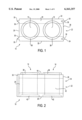
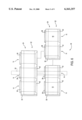
- FIG. 1 is a top view of a brick of this invention having two vertical passageways.
- FIG. 2 is a side view of the brick illustrated in FIG. 1.
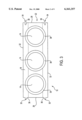
- FIG. 3 is a top view of a brick of this invention having three vertical passageways.
- FIG. 4 is a side view of the brick illustrated in FIG. 3.
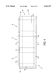
- FIG. 5 is a partial, exploded view of a wall construction using bricks of this invention having two vertical passageways.
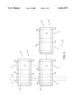
- FIG. 6 is a partial, exploded view of another type of wall construction using bricks of this invention having two and three vertical passageways.
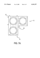
- FIGS. 7A-7F are top views of wall corners.
- FIG. 7A shows two bricks with two vertical passageways assembled vertically with an approximately 90° corner.
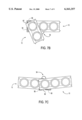
- FIG. 7B shows two bricks, one having two vertical passageways and the other having three vertical passagways, assembled vertically with an approximately 45° corner.
- FIG. 7C shows two bricks, each having three vertical passageways, assembled vertically with an approximately 120° corner.
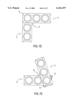
- FIG. 7D shows two bricks, each having three vertical passageways, assembled vertically with an approximately 90° corner.
- FIG. 7E shows two bricks, each having three vertical passageways, assembled vertically with an approximately 45° corner.
- FIG. 7F shows three bricks, two having two vertical passageways and one having three vertical passageways, assembled vertically in an approximately Z shaped configuration.
- the brick 10 of this invention has preferably two or three cylindrical passageways or bores 14 running from the top 18 to the bottom 20 and a cylindrical passageway or bore 22 running from one end 26 to the opposite end 28. These bores 14, 22 intersect.
- the width and height of a standard brick is about half its length.
- all bricks 10 preferably have a square cross-ssection.
- the width and height of the bricks 10 with two vertical passageways 14 are about half the length.
- the width and height of the bricks 10 with three vertical passageways 14 are about one third the length.
- the bricks 10 with three vertical passageways 14 are about one third longer than the bricks 10 with two vertical passageways 14.
- the brick 10 of this invention also has, preferably, two linear grooves 34 at one end 26 and two linear projections 30 at the other end 28 which are spaced apart from the bore 26, are of identical shape, and preferably run parallel to the sides 32. However, the grooves 34 are slightly larger than the projections 30.
- the projections 30 and grooves 34 run from top 18 to bottom 20 and are preferably designed with a break 36 for ease of assembly.
- FIGS. 5 and 6 illustrate wall 46 construction using bricks 10 of this invention. It can be seen from these views that bricks 10 can be assembled in usual fashion with the bricks 10 vertically aligned or offset by half or one third a brick 10 in each course.
- the top to bottom bores 14 run in the vertical plane and the end to end bores 22 run in the horizontal plane.
- the linear projections 30 from one brick 10 interlock with the linear grooves 34 of the adjacent brick 10.
- the annular projections 38 of one brick 10 interlock with the annular grooves 42 of another brick 10.
- the linear grooves 34 and projections 30 interlock horizontally and the annular grooves 42 and projections 38 interlock vertically.
- the bricks 10 interlock in two orthogonal planes and the wall 46 achieves strength and rigidity in two dimensions. Also, a network of interconnecting horizontal 22 and vertical 14 passageways is created within the wall 46. No mortar is needed between courses or bricks 10. The bricks 10 will simply interlock rigidly without the need for mortar.
- FIGS. 7A-7F each show a top view of two or more bricks 10 mated vertically via the annular grooves 42 and projections 38, at various corner angles 54.
- FIGS. 7A-7E one brick in an upper course and one brick in the next lower course are illustrated.
- FIG. 7F two bricks in an an upper course and one brick in the next lower course are illustrated.
- the corners 56 of bricks 10 assembled in the illustrative configurations shown in FIGS. 7B, 7C, 7E and 7F could be cut in order to provide smooth constructions at the wall corners 62.
- the wall can be built over reinforcing rods or posts 50 in conventional manner.
- the reinforcing posts 50 should be smaller than the vertical bore 14. See FIGS. 5 and 6.
- the bores 14, 22 in the wall can be filled with concrete.
- the interconnecting passageways 14, 22 can also be used to run plumbing or electric supply lines and the like. Such utilities can be installed in the wall 46 as it is being constructed.
- brick 10 of this invention can be used to simply and economically construct walls 46, leading to cheaper construction costs and thus cheaper housing costs.
- bricks 10 with two and three vertical passageways 14 have been illustrated, it is theoretically possible to fabricate bricks 10 with any number of vertical passageways 14. In order to ensure proper mating, the length of such bricks would increase by an amount equal to the width or height of the brick 10 with each added passageway 14. However, bricks 10 with two and three vertical passageways 14 would be the most useful. While the words “top” and “bottom” have been used for convenience in understanding this invention, it will be readily understood that what side of the bricks 10 in a wall 46 is up is immaterial.
- FIGS. 1 through 7F The following reference numerals are used on FIGS. 1 through 7F:
Abstract
Description
Claims (36)
Priority Applications (1)
| Application Number | Priority Date | Filing Date | Title |
|---|---|---|---|
| US09/510,491 US6161357A (en) | 1998-09-25 | 2000-02-23 | Bidirectionally interlocking, hollow brick wall system |
Applications Claiming Priority (2)
| Application Number | Priority Date | Filing Date | Title |
|---|---|---|---|
| US16155298A | 1998-09-25 | 1998-09-25 | |
| US09/510,491 US6161357A (en) | 1998-09-25 | 2000-02-23 | Bidirectionally interlocking, hollow brick wall system |
Related Parent Applications (1)
| Application Number | Title | Priority Date | Filing Date |
|---|---|---|---|
| US16155298A Continuation | 1998-09-25 | 1998-09-25 |
Publications (1)
| Publication Number | Publication Date |
|---|---|
| US6161357A true US6161357A (en) | 2000-12-19 |
Family
ID=22581651
Family Applications (1)
| Application Number | Title | Priority Date | Filing Date |
|---|---|---|---|
| US09/510,491 Expired - Fee Related US6161357A (en) | 1998-09-25 | 2000-02-23 | Bidirectionally interlocking, hollow brick wall system |
Country Status (5)
| Country | Link |
|---|---|
| US (1) | US6161357A (en) |
| AU (1) | AU6145899A (en) |
| CA (1) | CA2345630A1 (en) |
| MX (1) | MXPA01003110A (en) |
| WO (1) | WO2000019026A1 (en) |
Cited By (42)
| Publication number | Priority date | Publication date | Assignee | Title |
|---|---|---|---|---|
| US6530772B1 (en) | 2000-06-30 | 2003-03-11 | Consolidated Minerals, Inc. | System for making aerated concrete blocks having at least one passageway drilled therein |
| US6533970B1 (en) | 2000-06-30 | 2003-03-18 | Consolidated Minerals, Inc. | Method for making aerated concrete blocks having at least one passageway drilled therein |
| US6571525B2 (en) * | 2001-08-01 | 2003-06-03 | J. David Coleman | Construction block |
| WO2003050362A2 (en) * | 2001-12-13 | 2003-06-19 | Joubert, Dorothy | Building construction and building units for use therein |
| US6641452B2 (en) | 2001-09-05 | 2003-11-04 | Susan J. Racine | Building block |
| WO2004001151A1 (en) * | 1999-04-12 | 2003-12-31 | Cercorp Initiatives Inc. | Flexible interlocking wall system |
| US6889479B2 (en) | 2003-04-28 | 2005-05-10 | Douglas G. Thorpe | Building block |
| US20050108972A1 (en) * | 2003-11-24 | 2005-05-26 | Aldo Banova | Interlocking masonry articles and methods thereof |
| US20050257481A1 (en) * | 2004-04-13 | 2005-11-24 | Shaw Reece F | Article of manufacture for building structures made from precast concrete units and process for making structural system |
| US20060059824A1 (en) * | 2004-09-15 | 2006-03-23 | Austin Barbisch | Block structure |
| US7191571B2 (en) | 2002-06-26 | 2007-03-20 | Schools Jody L | Modular construction blocks, building structures, kits, and methods for forming building structures |
| US20070079566A1 (en) * | 2001-11-20 | 2007-04-12 | Neill Jeremiah F | Modular building block system |
| US20070271868A1 (en) * | 2006-05-23 | 2007-11-29 | Abella Ricardo E | System of brick with rod |
| US20080216436A1 (en) * | 2000-03-10 | 2008-09-11 | Alberto Rodriguez Carassus | Self-locking block and complementary pieces for the raising of pillars and free-standing walls |
| US20090113815A1 (en) * | 2007-10-26 | 2009-05-07 | Terah Earl Woodcock | Tapered Hexagon Building Block |
| US20090173027A1 (en) * | 2006-05-10 | 2009-07-09 | Kerry Bennett | Concrete masonry hollow block |
| US20090301003A1 (en) * | 2006-05-02 | 2009-12-10 | Nunez-Vargas Mariano | Wall structure with hollow plastic modules |
| US20100287871A1 (en) * | 2009-05-12 | 2010-11-18 | Vanocur Refractories, L.L.C. | Corbel repairs of coke ovens |
| US20100300028A1 (en) * | 2007-12-18 | 2010-12-02 | Innovation Central Pty Ltd | Improved protection barrier and components thereof |
| US20100307095A1 (en) * | 2009-06-09 | 2010-12-09 | Adams Wendell B | Bulk liquid and material delivery device and construction block |
| GB2472068A (en) * | 2009-07-23 | 2011-01-26 | Innovation Ltd Const | Wall structure formed from insulating parallelepiped blocks |
| GB2477728A (en) * | 2010-02-10 | 2011-08-17 | Alan Mark Seddon | Modular moulded brick for an inspection chamber |
| US20110225909A1 (en) * | 2000-03-10 | 2011-09-22 | Alberto Rodriguez Carassus | Self-locking block and complementary blocks for the construction of pillars, free-standing walls, rooms, and buildings |
| US20130036696A1 (en) * | 2011-08-08 | 2013-02-14 | Casey Moroschan | Mortarless hollow core block wall construction system |
| US20130247497A1 (en) * | 2010-09-15 | 2013-09-26 | Mcmaster University | Self-reinforced masonry blocks, walls made from self-reinforced masonry blocks, and method for making self-reinforced masonry blocks |
| US20140102032A1 (en) * | 2010-04-30 | 2014-04-17 | Anchor Wall Systems, Inc. | Free-standing wall arrangement and methods |
| US20150075106A1 (en) * | 2012-03-30 | 2015-03-19 | Vandenbempt Patent Cv | Building block, as well as an insert piece to be applied in such a building block |
| US20150159371A1 (en) * | 2011-03-28 | 2015-06-11 | Alberto Rodriguez Carassus | Self-locking block and complementary pieces for the raising of pillars and free-standing walls |
| EP2894270A1 (en) * | 2014-01-14 | 2015-07-15 | Stefano Savelloni | Interlocking modular element for construction of structures and furniture. |
| US9089096B1 (en) * | 2013-10-09 | 2015-07-28 | Michael R. Ulrich | Pre-formed landscape barrier |
| US9145249B2 (en) | 2013-06-11 | 2015-09-29 | Wendell B. Adams | Bulk liquid/material construction block utility kit |
| US20160237707A1 (en) * | 2012-09-07 | 2016-08-18 | Insta-Place Llc | System and method for constructing a set or a stage |
| US9777499B2 (en) * | 2015-03-13 | 2017-10-03 | National Applied Research Laboratories | Precast segment, stacking structure and energy dissipation column thereof |
| US10010805B2 (en) | 2012-09-07 | 2018-07-03 | Emagispace, Inc. | System and method for constructing a set or a stage |
| US10113305B2 (en) * | 2014-08-01 | 2018-10-30 | Just Biofiber Structural Solutions Corp. | Load bearing interlocking structural blocks and tensioning system |
| US10415241B2 (en) | 2016-03-08 | 2019-09-17 | Excel Project Management Ltd. | Monolithic retaining wall |
| US10584502B2 (en) | 2016-09-09 | 2020-03-10 | Excel Project Management Ltd. | Arch-support system |
| US10781588B1 (en) * | 2018-01-25 | 2020-09-22 | Marc R Nadeau | Integrated, post-tensioned, building construction system |
| US20210180283A1 (en) * | 2019-12-12 | 2021-06-17 | Robert Daggett | Interlocking blocking system for retaining walls and other uses |
| US20210348383A1 (en) * | 2018-10-15 | 2021-11-11 | Start Somewhere gemeinnützige GmbH | Wall block, range of wall blocks, and formwork for producing a wall block |
| US11173413B2 (en) * | 2019-02-27 | 2021-11-16 | Takahara Lumber Co., Ltd. | Block member set |
| US11408173B2 (en) * | 2019-11-22 | 2022-08-09 | Lazarian World Homes | Foam as modular support |
Citations (9)
| Publication number | Priority date | Publication date | Assignee | Title |
|---|---|---|---|---|
| US786884A (en) * | 1904-05-28 | 1905-05-11 | Robert P Faulkner | Building-block. |
| US800385A (en) * | 1905-03-02 | 1905-09-26 | John Henry Miller | Building-block. |
| US950140A (en) * | 1909-03-22 | 1910-02-22 | J H Kimmons | Portable fireproof building. |
| US1242087A (en) * | 1916-03-23 | 1917-10-02 | Clarence W Waddell | Interlocking tile. |
| US2911818A (en) * | 1955-11-10 | 1959-11-10 | Smith Charles | Interlocking building blocks |
| US4426815A (en) * | 1979-12-10 | 1984-01-24 | Sam Brown | Mortarless concrete block system having reinforcing bond beam courses |
| US5421135A (en) * | 1993-06-29 | 1995-06-06 | Concrete Shop, Inc. | Interlocking building blocks |
| US5457926A (en) * | 1993-11-03 | 1995-10-17 | Templeton Trust | Interlocking block |
| US5651642A (en) * | 1995-03-17 | 1997-07-29 | Kelley, Jr.; Michael L. | Concrete building blocks |
Family Cites Families (7)
| Publication number | Priority date | Publication date | Assignee | Title |
|---|---|---|---|---|
| IT427849A (en) * | ||||
| DE87663C (en) * | 1895-12-31 | |||
| US1582735A (en) * | 1925-02-16 | 1926-04-27 | Clark W Cooper | Building block |
| US1785499A (en) * | 1928-04-07 | 1930-12-16 | Sayers Fred | Building block |
| US2703487A (en) * | 1949-09-30 | 1955-03-08 | Ossoinack Andrea | Interlocking hollow building block |
| AU213090B2 (en) * | 1955-08-16 | 1956-11-15 | ChiaradÃa Pierre | Improvements in or relating to hollow building blocks and bricks |
| US3030093A (en) * | 1960-03-21 | 1962-04-17 | George P Reintjes | Checkerwork |
-
1999
- 1999-09-14 CA CA002345630A patent/CA2345630A1/en not_active Abandoned
- 1999-09-14 MX MXPA01003110A patent/MXPA01003110A/en not_active IP Right Cessation
- 1999-09-14 AU AU61458/99A patent/AU6145899A/en not_active Abandoned
- 1999-09-14 WO PCT/US1999/021187 patent/WO2000019026A1/en active Application Filing
-
2000
- 2000-02-23 US US09/510,491 patent/US6161357A/en not_active Expired - Fee Related
Patent Citations (9)
| Publication number | Priority date | Publication date | Assignee | Title |
|---|---|---|---|---|
| US786884A (en) * | 1904-05-28 | 1905-05-11 | Robert P Faulkner | Building-block. |
| US800385A (en) * | 1905-03-02 | 1905-09-26 | John Henry Miller | Building-block. |
| US950140A (en) * | 1909-03-22 | 1910-02-22 | J H Kimmons | Portable fireproof building. |
| US1242087A (en) * | 1916-03-23 | 1917-10-02 | Clarence W Waddell | Interlocking tile. |
| US2911818A (en) * | 1955-11-10 | 1959-11-10 | Smith Charles | Interlocking building blocks |
| US4426815A (en) * | 1979-12-10 | 1984-01-24 | Sam Brown | Mortarless concrete block system having reinforcing bond beam courses |
| US5421135A (en) * | 1993-06-29 | 1995-06-06 | Concrete Shop, Inc. | Interlocking building blocks |
| US5457926A (en) * | 1993-11-03 | 1995-10-17 | Templeton Trust | Interlocking block |
| US5651642A (en) * | 1995-03-17 | 1997-07-29 | Kelley, Jr.; Michael L. | Concrete building blocks |
Cited By (60)
| Publication number | Priority date | Publication date | Assignee | Title |
|---|---|---|---|---|
| US6758020B2 (en) * | 1997-09-08 | 2004-07-06 | Cercorp Initiatives Incorporated | Flexible interlocking wall system |
| WO2004001151A1 (en) * | 1999-04-12 | 2003-12-31 | Cercorp Initiatives Inc. | Flexible interlocking wall system |
| US20080216436A1 (en) * | 2000-03-10 | 2008-09-11 | Alberto Rodriguez Carassus | Self-locking block and complementary pieces for the raising of pillars and free-standing walls |
| US20110225909A1 (en) * | 2000-03-10 | 2011-09-22 | Alberto Rodriguez Carassus | Self-locking block and complementary blocks for the construction of pillars, free-standing walls, rooms, and buildings |
| US6530772B1 (en) | 2000-06-30 | 2003-03-11 | Consolidated Minerals, Inc. | System for making aerated concrete blocks having at least one passageway drilled therein |
| US6533970B1 (en) | 2000-06-30 | 2003-03-18 | Consolidated Minerals, Inc. | Method for making aerated concrete blocks having at least one passageway drilled therein |
| US6571525B2 (en) * | 2001-08-01 | 2003-06-03 | J. David Coleman | Construction block |
| US6641452B2 (en) | 2001-09-05 | 2003-11-04 | Susan J. Racine | Building block |
| US20070079566A1 (en) * | 2001-11-20 | 2007-04-12 | Neill Jeremiah F | Modular building block system |
| WO2003050362A2 (en) * | 2001-12-13 | 2003-06-19 | Joubert, Dorothy | Building construction and building units for use therein |
| WO2003050362A3 (en) * | 2001-12-13 | 2003-12-24 | Joubert Dorothy | Building construction and building units for use therein |
| US7191571B2 (en) | 2002-06-26 | 2007-03-20 | Schools Jody L | Modular construction blocks, building structures, kits, and methods for forming building structures |
| US6889479B2 (en) | 2003-04-28 | 2005-05-10 | Douglas G. Thorpe | Building block |
| US6962028B2 (en) * | 2003-11-24 | 2005-11-08 | Aldo Banova | Interlocking masonry articles and methods thereof |
| US20050108972A1 (en) * | 2003-11-24 | 2005-05-26 | Aldo Banova | Interlocking masonry articles and methods thereof |
| US7546712B2 (en) * | 2004-04-13 | 2009-06-16 | Shaw Reece F | System of stacked concrete blocks, each block having a tire wall stack therewithin surrounding a hollow core through which a vertical reinforcing member extends and reinforcing bars in mortar in void between adjacent blocks |
| US20050257481A1 (en) * | 2004-04-13 | 2005-11-24 | Shaw Reece F | Article of manufacture for building structures made from precast concrete units and process for making structural system |
| US20060059824A1 (en) * | 2004-09-15 | 2006-03-23 | Austin Barbisch | Block structure |
| US20090301003A1 (en) * | 2006-05-02 | 2009-12-10 | Nunez-Vargas Mariano | Wall structure with hollow plastic modules |
| US8297012B2 (en) * | 2006-05-02 | 2012-10-30 | Nunez-Vargas Mariano | Wall structure with hollow plastic modules |
| US20090173027A1 (en) * | 2006-05-10 | 2009-07-09 | Kerry Bennett | Concrete masonry hollow block |
| US20070271868A1 (en) * | 2006-05-23 | 2007-11-29 | Abella Ricardo E | System of brick with rod |
| US20090113815A1 (en) * | 2007-10-26 | 2009-05-07 | Terah Earl Woodcock | Tapered Hexagon Building Block |
| US20100300028A1 (en) * | 2007-12-18 | 2010-12-02 | Innovation Central Pty Ltd | Improved protection barrier and components thereof |
| US8266853B2 (en) * | 2009-05-12 | 2012-09-18 | Vanocur Refractories Llc | Corbel repairs of coke ovens |
| US20100287871A1 (en) * | 2009-05-12 | 2010-11-18 | Vanocur Refractories, L.L.C. | Corbel repairs of coke ovens |
| US20100307095A1 (en) * | 2009-06-09 | 2010-12-09 | Adams Wendell B | Bulk liquid and material delivery device and construction block |
| US8316610B2 (en) * | 2009-06-09 | 2012-11-27 | Adams Wendell B | Bulk liquid and material delivery device and construction block |
| GB2472068A (en) * | 2009-07-23 | 2011-01-26 | Innovation Ltd Const | Wall structure formed from insulating parallelepiped blocks |
| WO2011010127A3 (en) * | 2009-07-23 | 2012-03-22 | Construction Innovation Ltd | Concrete wall structure |
| WO2011010127A2 (en) | 2009-07-23 | 2011-01-27 | Construction Innovation Ltd | Concrete wall structure |
| GB2477728A (en) * | 2010-02-10 | 2011-08-17 | Alan Mark Seddon | Modular moulded brick for an inspection chamber |
| US9169642B2 (en) * | 2010-04-30 | 2015-10-27 | Anchor Wall Systems, Inc. | Free-standing wall arrangement and methods |
| US9745743B2 (en) | 2010-04-30 | 2017-08-29 | Anchor Wall Systems, Inc. | Free-standing wall arrangement and methods |
| US9441370B2 (en) | 2010-04-30 | 2016-09-13 | Anchor Wall Systems, Inc. | Free-standing wall arrangement and methods |
| US20140102032A1 (en) * | 2010-04-30 | 2014-04-17 | Anchor Wall Systems, Inc. | Free-standing wall arrangement and methods |
| US9175469B2 (en) * | 2010-09-15 | 2015-11-03 | Mcmaster University | Self-reinforced masonry blocks, walls made from self-reinforced masonry blocks, and method for making self-reinforced masonry blocks |
| US20130247497A1 (en) * | 2010-09-15 | 2013-09-26 | Mcmaster University | Self-reinforced masonry blocks, walls made from self-reinforced masonry blocks, and method for making self-reinforced masonry blocks |
| US20150159371A1 (en) * | 2011-03-28 | 2015-06-11 | Alberto Rodriguez Carassus | Self-locking block and complementary pieces for the raising of pillars and free-standing walls |
| US9187895B2 (en) * | 2011-03-28 | 2015-11-17 | Alberto Rodriguez Carassus | Self-locking block and complementary pieces for the raising of pillars and free-standing walls |
| US20130036696A1 (en) * | 2011-08-08 | 2013-02-14 | Casey Moroschan | Mortarless hollow core block wall construction system |
| US9593480B2 (en) * | 2012-03-30 | 2017-03-14 | Vandenbempt Patent Comm. V | Building block, as well as an insert piece to be applied in such a building block |
| US20150075106A1 (en) * | 2012-03-30 | 2015-03-19 | Vandenbempt Patent Cv | Building block, as well as an insert piece to be applied in such a building block |
| US10010805B2 (en) | 2012-09-07 | 2018-07-03 | Emagispace, Inc. | System and method for constructing a set or a stage |
| US20160237707A1 (en) * | 2012-09-07 | 2016-08-18 | Insta-Place Llc | System and method for constructing a set or a stage |
| US9644381B2 (en) * | 2012-09-07 | 2017-05-09 | Insta-Place Llc | System and method for constructing a set or a stage |
| US10167632B2 (en) | 2012-09-07 | 2019-01-01 | Emagispace, Inc. | System and method for constructing a set or a stage |
| US9145249B2 (en) | 2013-06-11 | 2015-09-29 | Wendell B. Adams | Bulk liquid/material construction block utility kit |
| US9089096B1 (en) * | 2013-10-09 | 2015-07-28 | Michael R. Ulrich | Pre-formed landscape barrier |
| EP2894270A1 (en) * | 2014-01-14 | 2015-07-15 | Stefano Savelloni | Interlocking modular element for construction of structures and furniture. |
| US10113305B2 (en) * | 2014-08-01 | 2018-10-30 | Just Biofiber Structural Solutions Corp. | Load bearing interlocking structural blocks and tensioning system |
| US9777499B2 (en) * | 2015-03-13 | 2017-10-03 | National Applied Research Laboratories | Precast segment, stacking structure and energy dissipation column thereof |
| US10415241B2 (en) | 2016-03-08 | 2019-09-17 | Excel Project Management Ltd. | Monolithic retaining wall |
| US10584502B2 (en) | 2016-09-09 | 2020-03-10 | Excel Project Management Ltd. | Arch-support system |
| US10781588B1 (en) * | 2018-01-25 | 2020-09-22 | Marc R Nadeau | Integrated, post-tensioned, building construction system |
| US20210348383A1 (en) * | 2018-10-15 | 2021-11-11 | Start Somewhere gemeinnützige GmbH | Wall block, range of wall blocks, and formwork for producing a wall block |
| US11173413B2 (en) * | 2019-02-27 | 2021-11-16 | Takahara Lumber Co., Ltd. | Block member set |
| US11408173B2 (en) * | 2019-11-22 | 2022-08-09 | Lazarian World Homes | Foam as modular support |
| US20210180283A1 (en) * | 2019-12-12 | 2021-06-17 | Robert Daggett | Interlocking blocking system for retaining walls and other uses |
| US11686063B2 (en) * | 2019-12-12 | 2023-06-27 | Robert Daggett | Interlocking blocking system for retaining walls and other uses |
Also Published As
| Publication number | Publication date |
|---|---|
| AU6145899A (en) | 2000-04-17 |
| MXPA01003110A (en) | 2003-07-14 |
| WO2000019026A1 (en) | 2000-04-06 |
| CA2345630A1 (en) | 2000-04-06 |
| WO2000019026A9 (en) | 2001-12-13 |
Similar Documents
| Publication | Publication Date | Title |
|---|---|---|
| US6161357A (en) | Bidirectionally interlocking, hollow brick wall system | |
| CA1152770A (en) | Mortarless concrete block system having reinforcing bond beam courses | |
| US7174687B2 (en) | Web offset lug dry-stack system | |
| EP0767855B1 (en) | Interlocking mortarless building block system | |
| CA1083377A (en) | Prefabricated self-supporting modular room elements | |
| EP0163117B1 (en) | Bettered, high thermal, and/or sound insulating modular elements suitable for buildings | |
| CA2346719A1 (en) | Building block | |
| US20070094989A1 (en) | Modular superblock interlocking building system | |
| CA2577424C (en) | Block and connector system | |
| US4671039A (en) | Block | |
| CZ473289A3 (en) | Self-supporting forming elements, particularly for casting masonry and other concrete structures | |
| US20090188186A1 (en) | Building Construction System and Structural Modules Thereof | |
| US6745537B1 (en) | Modular wall or fence construction system | |
| US4766711A (en) | Building element and a construction method using such an element | |
| US4719737A (en) | Interlocking construction block | |
| WO1990004688A2 (en) | A building system | |
| CN112789385A (en) | Building blocks (variants) | |
| US20220298741A1 (en) | Modular wall panel section, system and method thereof | |
| CA2091226C (en) | Blocks and their use | |
| US20050055980A1 (en) | Building element and structure | |
| WO2008108765A1 (en) | Concrete block for forming columns | |
| KR200165432Y1 (en) | Block for consfructing and its assembly | |
| KR20190102336A (en) | Assembly interlocking building block and interlocking block construction system | |
| WO2023028152A1 (en) | Masonry blocks for reinforced masonry construction | |
| HU218253B (en) | Prefabricated spatial element |
Legal Events
| Date | Code | Title | Description |
|---|---|---|---|
| FEPP | Fee payment procedure |
Free format text: PAYOR NUMBER ASSIGNED (ORIGINAL EVENT CODE: ASPN); ENTITY STATUS OF PATENT OWNER: SMALL ENTITY |
|
| FEPP | Fee payment procedure |
Free format text: PAYOR NUMBER ASSIGNED (ORIGINAL EVENT CODE: ASPN); ENTITY STATUS OF PATENT OWNER: SMALL ENTITY Free format text: PAYER NUMBER DE-ASSIGNED (ORIGINAL EVENT CODE: RMPN); ENTITY STATUS OF PATENT OWNER: SMALL ENTITY |
|
| FPAY | Fee payment |
Year of fee payment: 4 |
|
| REMI | Maintenance fee reminder mailed | ||
| FPAY | Fee payment |
Year of fee payment: 8 |
|
| SULP | Surcharge for late payment |
Year of fee payment: 7 |
|
| REMI | Maintenance fee reminder mailed | ||
| LAPS | Lapse for failure to pay maintenance fees | ||
| STCH | Information on status: patent discontinuation |
Free format text: PATENT EXPIRED DUE TO NONPAYMENT OF MAINTENANCE FEES UNDER 37 CFR 1.362 |
|
| FP | Lapsed due to failure to pay maintenance fee |
Effective date: 20121219 |