US6161927A - Ink jet printer cartridge with press-on lid - Google Patents
Ink jet printer cartridge with press-on lid Download PDFInfo
- Publication number
- US6161927A US6161927A US09/512,571 US51257100A US6161927A US 6161927 A US6161927 A US 6161927A US 51257100 A US51257100 A US 51257100A US 6161927 A US6161927 A US 6161927A
- Authority
- US
- United States
- Prior art keywords
- spacer
- reservoir
- ink
- connecting posts
- lid
- Prior art date
- Legal status (The legal status is an assumption and is not a legal conclusion. Google has not performed a legal analysis and makes no representation as to the accuracy of the status listed.)
- Expired - Lifetime
Links
Images
Classifications
-
- B—PERFORMING OPERATIONS; TRANSPORTING
- B41—PRINTING; LINING MACHINES; TYPEWRITERS; STAMPS
- B41J—TYPEWRITERS; SELECTIVE PRINTING MECHANISMS, i.e. MECHANISMS PRINTING OTHERWISE THAN FROM A FORME; CORRECTION OF TYPOGRAPHICAL ERRORS
- B41J2/00—Typewriters or selective printing mechanisms characterised by the printing or marking process for which they are designed
- B41J2/005—Typewriters or selective printing mechanisms characterised by the printing or marking process for which they are designed characterised by bringing liquid or particles selectively into contact with a printing material
- B41J2/01—Ink jet
- B41J2/17—Ink jet characterised by ink handling
- B41J2/175—Ink supply systems ; Circuit parts therefor
- B41J2/17503—Ink cartridges
- B41J2/17513—Inner structure
-
- B—PERFORMING OPERATIONS; TRANSPORTING
- B41—PRINTING; LINING MACHINES; TYPEWRITERS; STAMPS
- B41J—TYPEWRITERS; SELECTIVE PRINTING MECHANISMS, i.e. MECHANISMS PRINTING OTHERWISE THAN FROM A FORME; CORRECTION OF TYPOGRAPHICAL ERRORS
- B41J2/00—Typewriters or selective printing mechanisms characterised by the printing or marking process for which they are designed
- B41J2/005—Typewriters or selective printing mechanisms characterised by the printing or marking process for which they are designed characterised by bringing liquid or particles selectively into contact with a printing material
- B41J2/01—Ink jet
- B41J2/17—Ink jet characterised by ink handling
- B41J2/175—Ink supply systems ; Circuit parts therefor
- B41J2/17503—Ink cartridges
- B41J2/17553—Outer structure
-
- B—PERFORMING OPERATIONS; TRANSPORTING
- B41—PRINTING; LINING MACHINES; TYPEWRITERS; STAMPS
- B41J—TYPEWRITERS; SELECTIVE PRINTING MECHANISMS, i.e. MECHANISMS PRINTING OTHERWISE THAN FROM A FORME; CORRECTION OF TYPOGRAPHICAL ERRORS
- B41J2/00—Typewriters or selective printing mechanisms characterised by the printing or marking process for which they are designed
- B41J2/005—Typewriters or selective printing mechanisms characterised by the printing or marking process for which they are designed characterised by bringing liquid or particles selectively into contact with a printing material
- B41J2/01—Ink jet
- B41J2/17—Ink jet characterised by ink handling
- B41J2/175—Ink supply systems ; Circuit parts therefor
- B41J2/17503—Ink cartridges
- B41J2/17559—Cartridge manufacturing
Definitions
- filled ink jet cartridges are produced by first forming the main body of the cartridge.
- the main body constitutes a bottom and four side walls defining an ink cavity of the ink jet cartridge.
- a foam piece is then typically pressed into the body cavity of the cartridge, and the cavity and foam piece are then filled with ink by means of an open-ended top.
- a cover is placed on the now ink filled main body and attached to the side walls thereto.
- this attachment is made by means of an ultrasonic weld which may vibrate the cartridge at a frequency of 20 to 40 kHz. The weld completely seals the cover to the side walls of the ink jet cartridge.
- a further object of the invention is to provide an ink jet cartridge having improved venting for gas pressure equalization.
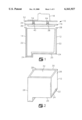
- FIG. 1 is a cross-sectional view, not to scale, of an ink cartridge assembly according to the invention
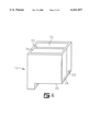
- FIG. 2 is a perspective view of a cartridge body according to the invention.
- the ink reservoir body 12 is generally in the shape of an open-faced prism, preferably a open faced rectangular prism and has an open-ended cavity 32 defined by the combination of the bottom portion 20, the side portions 22, and the reservoir periphery 30.
- the cavity 32 has a generally cubical shape.
- a foam insert 14 is disposed within the open-ended cavity 32 of the reservoir body.
- the foam insert 14 acts as a sponge to absorb and wick printing ink within the ink jet printer cartridge 10.
- the foam insert 14 may be formed of any suitable spongelike material.
- the foam insert may be a reticulated or open cell foam such as a polyurethane foam formed from the polymerization of a polyol and toluene diisocyanate as is well known in the art or from other suitable foams.
- the foam insert is formed of a felted polyurethane material.
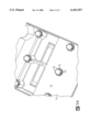
- the spacer 16 is fixedly attached to the ink reservoir body 12 preferably by means of ultrasonic welding. When being attached the spacer 16 is positioned so that the second side 36 contacts the ink reservoir periphery 30 along the top wall edges 28 of the ink reservoir body 12.
- the printing ink may be any ink suitable for ink jet printing equipment including pigment and dye based inks such as described in U.S. Pat. Nos. 5,198,022 to Aulick et al., 5,254,160 to Beach et al., 5,494,507 to Beach et al., 5,589,522 to Beach et al., 5,656,071 to Kappele et al., and 5,925,692 to Kappele et al the disclosures of which are incorporated herein by reference as if fully set forth.
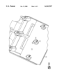
- a reservoir lid 18 is fixedly connected to the spacer 16. (See FIGS. 1 and 4).
- the reservoir lid 18 has a generally planar first side 52 and a second side 54. When fixedly connected to the spacer 16, the reservoir lid 18 is positioned so that the first side 52 faces the first side 34 of the spacer 16.
- the lid 18 cannot be easily removed without the applying substantial force between the spacer 16 and lid 18.
- the connecting posts 54-64 do not engage the holes 38-48 sufficiently to form an airtight seal between the holes and the connecting posts.
- the number, size, and arrangement of the connecting posts on the first side 52 of the reservoir lid 18 is chosen so as to ensure that the connecting posts engage the plurality of holes in the spacer 16.
- the bottom side 52 of the reservoir lid 18 has at least 6 connecting posts but may contain more or fewer connecting posts provided the spacer 16 contains at least as many holes as there are posts and the number of posts are sufficient to provide a substantially non-removable connection between the lid and spacer.
- each connecting post 54-64 engages the plurality of holes 38-48 in the spacer 16 nonhermetically. In a preferred embodiment of the invention, this is accomplished by forming within each connecting post such as post 56 at least one gas flow channel 66 as shown in FIGS. 5A and 5B.
- the gas flow channel 66 provides for gas flow communication between the first side 34 of the spacer 16 and the second side 36 of the spacer 16 while the reservoir lid 18 is fixedly connected to the spacer 16.
- the pressure inside the cavity 32 of the ink reservoir 12 remains substantially equal to that outside of the reservoir 12 even after a substantial portion of the ink volume as been used and consumed.
- the pressure inside the cavity 32 of the ink reservoir 12 remains substantially equal to that outside of the reservoir 12 even after a substantial portion of the ink volume as been used and consumed.
- each connection post also comprises at least one deformable rib structure 68.
- the rib structure 68 deforms so as to allow the connecting posts such as post 56 to more firmly engage the hole in the spacer 16.
- a plurality of deformable rib structures 68 may be formed on the outer surface of the connecting post 56 which deform and engage the inner circumference of the hole in the spacer 16.
- the connection post 56 may have one deformable rib in the center that deforms when the outer surface of the post engages the inner circumference of the spacer hole.
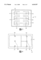
- the ink reservoir body 12 may additionally comprise one or more internal common partition walls 70.
- Partition wall 70 divides the interior of the ink reservoir body 12 into a plurality of open-ended cavities 72 and 74.
- the common partition wall 70 is made of the same materials as the bottom portion 20 and side portions 22 of the ink reservoir body 12 (FIG. 1) and is formed and attached to the ink reservoir body 12 in analogous manner.
- Each of the plurality of open-ended cavities 72 and 74 formed in the ink reservoir body 12 can function as an ink supply reservoir.
- foam inserts may be disposed in the open-ended cavities 72, 74 to absorb and retain ink.
- Each of the open-ended cavities 72, 74 may be filled with ink by the methods described above and since the cavities are sealed from each other by the partition wall 70, each of the cavities 72, 74 and foam inserts therefor may be filled with a different type and or color or ink. Regardless of the number of cavities and foam inserts, the construction and attachment to the spacer 16 and lid 18 are similar to the methods described above with reference to FIG. 1.
Abstract
Description
Claims (26)
Priority Applications (1)
| Application Number | Priority Date | Filing Date | Title |
|---|---|---|---|
| US09/512,571 US6161927A (en) | 2000-02-24 | 2000-02-24 | Ink jet printer cartridge with press-on lid |
Applications Claiming Priority (1)
| Application Number | Priority Date | Filing Date | Title |
|---|---|---|---|
| US09/512,571 US6161927A (en) | 2000-02-24 | 2000-02-24 | Ink jet printer cartridge with press-on lid |
Publications (1)
| Publication Number | Publication Date |
|---|---|
| US6161927A true US6161927A (en) | 2000-12-19 |
Family
ID=24039660
Family Applications (1)
| Application Number | Title | Priority Date | Filing Date |
|---|---|---|---|
| US09/512,571 Expired - Lifetime US6161927A (en) | 2000-02-24 | 2000-02-24 | Ink jet printer cartridge with press-on lid |
Country Status (1)
| Country | Link |
|---|---|
| US (1) | US6161927A (en) |
Cited By (17)
| Publication number | Priority date | Publication date | Assignee | Title |
|---|---|---|---|---|
| US20030038076A1 (en) * | 2001-08-27 | 2003-02-27 | Detlef Schwarzwald | Membrane apparatus for receiving samples |
| US6595711B2 (en) * | 2000-05-26 | 2003-07-22 | Legacy Manufacturing, Llc | Printer cartridge having a foam retention clip |
| US20040046844A1 (en) * | 2002-06-28 | 2004-03-11 | Haan Maurice Johan Jozef | Ink tank |
| US20040095444A1 (en) * | 2002-11-19 | 2004-05-20 | Drummond James Paul | Laser welding methods and structures and control therefor including welded inkjet printheads |
| US20040150688A1 (en) * | 2003-01-30 | 2004-08-05 | Kin-Ming Kwan | Measuring laser light transmissivity in a to-be-welded region of a work piece |
| WO2004096549A2 (en) * | 2003-04-29 | 2004-11-11 | Hewlett-Packard Development Company, L.P. | Colour coded laser weldable ink cartridge reservoir |
| US20040257414A1 (en) * | 2003-06-18 | 2004-12-23 | Anderson James D. | Sealed fluidic interfaces utilizing laser welding |
| US6899417B1 (en) * | 1999-10-29 | 2005-05-31 | Seiko Epson Corporation | Ink cartridge for use in an ink jet recording apparatus |
| US20050140761A1 (en) * | 2003-12-26 | 2005-06-30 | Canon Kabushiki Kaisha | Ink jet recording cartridge |
| US20060238584A1 (en) * | 2005-04-22 | 2006-10-26 | Nu-Kote International, Inc. | Ink cartridge replacement lid |
| US20060262170A1 (en) * | 2005-05-17 | 2006-11-23 | Nu-Kote International, Inc. | Ink cartridge replacement lid |
| US20070002106A1 (en) * | 2002-10-07 | 2007-01-04 | Yoel Wazana | Resealed ink cartridge and method of manufacture |
| EP1375162A3 (en) * | 2002-06-28 | 2007-03-07 | Océ-Technologies B.V. | Ink tank for ink jet |
| US20080165230A1 (en) * | 2007-08-17 | 2008-07-10 | Thomas Richards | Method and device to prevent refill of cartridge |
| CN102452227A (en) * | 2010-10-22 | 2012-05-16 | 研能科技股份有限公司 | Multicolor spray-printing ink head module |
| US20160288516A1 (en) * | 2015-03-30 | 2016-10-06 | Seiko Epson Corporation | Liquid container |
| WO2018001443A1 (en) * | 2016-07-01 | 2018-01-04 | Hewlett-Packard Development Company, L.P. | Ink-jet print head assemblies with a spacer surrounding an ink fill port and method of manufacturing |
Citations (12)
| Publication number | Priority date | Publication date | Assignee | Title |
|---|---|---|---|---|
| US4432004A (en) * | 1980-11-03 | 1984-02-14 | U.S. Philips Corporation | Device for capping the jet nozzles of an ink jet printing head |
| US4992802A (en) * | 1988-12-22 | 1991-02-12 | Hewlett-Packard Company | Method and apparatus for extending the environmental operating range of an ink jet print cartridge |
| US5408134A (en) * | 1991-11-22 | 1995-04-18 | Samsung Electronics Co., Ltd. | Sub-step pulse generating circuit using the period of a step pulse |
| US5408256A (en) * | 1992-07-27 | 1995-04-18 | Repeat-O-Type Manufacturing Company, Inc. | Refillable color ink jet cartridge and method for making said cartridge |
| US5428381A (en) * | 1993-07-30 | 1995-06-27 | Xerox Corporation | Capping structure |
| US5488400A (en) * | 1992-11-12 | 1996-01-30 | Graphic Utilities, Inc. | Method for refilling ink jet cartridges |
| US5631682A (en) * | 1993-07-06 | 1997-05-20 | Brother Kogyo Kabushiki Kaisha | Printhead ink supply device |
| US5661510A (en) * | 1994-11-22 | 1997-08-26 | Lexmark International, Inc. | Ink-jet cartridge venting |
| US5663753A (en) * | 1994-11-14 | 1997-09-02 | Jetfill, Inc. | Recording cartridge with replaceable liquid-containing reservoir |
| US5751324A (en) * | 1996-03-14 | 1998-05-12 | Lexmark International, Inc. | Ink jet cartridge body with vented die cavity |
| US5967196A (en) * | 1997-04-14 | 1999-10-19 | Pelikan Produktions Ag | Refill device for an ink jet print head |
| US5975677A (en) * | 1997-04-30 | 1999-11-02 | Hewlett-Packard Co. | Multiple cartridge printhead assembly for use in an inkjet printing system |
-
2000
- 2000-02-24 US US09/512,571 patent/US6161927A/en not_active Expired - Lifetime
Patent Citations (12)
| Publication number | Priority date | Publication date | Assignee | Title |
|---|---|---|---|---|
| US4432004A (en) * | 1980-11-03 | 1984-02-14 | U.S. Philips Corporation | Device for capping the jet nozzles of an ink jet printing head |
| US4992802A (en) * | 1988-12-22 | 1991-02-12 | Hewlett-Packard Company | Method and apparatus for extending the environmental operating range of an ink jet print cartridge |
| US5408134A (en) * | 1991-11-22 | 1995-04-18 | Samsung Electronics Co., Ltd. | Sub-step pulse generating circuit using the period of a step pulse |
| US5408256A (en) * | 1992-07-27 | 1995-04-18 | Repeat-O-Type Manufacturing Company, Inc. | Refillable color ink jet cartridge and method for making said cartridge |
| US5488400A (en) * | 1992-11-12 | 1996-01-30 | Graphic Utilities, Inc. | Method for refilling ink jet cartridges |
| US5631682A (en) * | 1993-07-06 | 1997-05-20 | Brother Kogyo Kabushiki Kaisha | Printhead ink supply device |
| US5428381A (en) * | 1993-07-30 | 1995-06-27 | Xerox Corporation | Capping structure |
| US5663753A (en) * | 1994-11-14 | 1997-09-02 | Jetfill, Inc. | Recording cartridge with replaceable liquid-containing reservoir |
| US5661510A (en) * | 1994-11-22 | 1997-08-26 | Lexmark International, Inc. | Ink-jet cartridge venting |
| US5751324A (en) * | 1996-03-14 | 1998-05-12 | Lexmark International, Inc. | Ink jet cartridge body with vented die cavity |
| US5967196A (en) * | 1997-04-14 | 1999-10-19 | Pelikan Produktions Ag | Refill device for an ink jet print head |
| US5975677A (en) * | 1997-04-30 | 1999-11-02 | Hewlett-Packard Co. | Multiple cartridge printhead assembly for use in an inkjet printing system |
Cited By (40)
| Publication number | Priority date | Publication date | Assignee | Title |
|---|---|---|---|---|
| US20050168549A1 (en) * | 1999-10-29 | 2005-08-04 | Seiko Epson Corporation | Ink cartridge for use in an ink jet recording apparatus |
| US7090344B2 (en) | 1999-10-29 | 2006-08-15 | Seiko Epson Corporation | Ink cartridge for use in an ink jet recording apparatus |
| US6899417B1 (en) * | 1999-10-29 | 2005-05-31 | Seiko Epson Corporation | Ink cartridge for use in an ink jet recording apparatus |
| US6595711B2 (en) * | 2000-05-26 | 2003-07-22 | Legacy Manufacturing, Llc | Printer cartridge having a foam retention clip |
| US7658982B2 (en) * | 2001-08-27 | 2010-02-09 | Eppendorf Ag | Membrane apparatus for receiving samples |
| US20030038076A1 (en) * | 2001-08-27 | 2003-02-27 | Detlef Schwarzwald | Membrane apparatus for receiving samples |
| US20040046844A1 (en) * | 2002-06-28 | 2004-03-11 | Haan Maurice Johan Jozef | Ink tank |
| EP1375162A3 (en) * | 2002-06-28 | 2007-03-07 | Océ-Technologies B.V. | Ink tank for ink jet |
| US7048364B2 (en) | 2002-06-28 | 2006-05-23 | Oce-Technologies B.V. | Ink tank |
| US20070002106A1 (en) * | 2002-10-07 | 2007-01-04 | Yoel Wazana | Resealed ink cartridge and method of manufacture |
| US7740346B2 (en) * | 2002-10-07 | 2010-06-22 | Wazana Brothers International | Resealed ink cartridge and method of manufacture |
| US6974207B2 (en) * | 2002-11-19 | 2005-12-13 | Lexmark International, Inc. | Laser welding methods and structures and control therefor including welded inkjet printheads |
| US20040095444A1 (en) * | 2002-11-19 | 2004-05-20 | Drummond James Paul | Laser welding methods and structures and control therefor including welded inkjet printheads |
| US20040150688A1 (en) * | 2003-01-30 | 2004-08-05 | Kin-Ming Kwan | Measuring laser light transmissivity in a to-be-welded region of a work piece |
| US20050168744A1 (en) * | 2003-01-30 | 2005-08-04 | Lexmark International, Inc. | Measuring laser light transmissivity in a to-be-welded region of a work piece |
| US6980296B2 (en) | 2003-01-30 | 2005-12-27 | Lexmark International, Inc. | Measuring laser light transmissivity in a to-be-welded region of a work piece |
| US20060012792A1 (en) * | 2003-01-30 | 2006-01-19 | Lexmark International, Inc. | Measuring laser light transmissivity in a to-be-welded region of a work piece |
| US7245378B2 (en) | 2003-01-30 | 2007-07-17 | Lexmark International, Inc. | Measuring laser light transmissivity in a to-be-welded region of a work piece |
| US6948805B2 (en) | 2003-04-29 | 2005-09-27 | Hewlett-Packard Development Company, L.P. | Ink cartridge reservoir |
| WO2004096549A3 (en) * | 2003-04-29 | 2005-01-27 | Hewlett Packard Development Co | Colour coded laser weldable ink cartridge reservoir |
| WO2004096549A2 (en) * | 2003-04-29 | 2004-11-11 | Hewlett-Packard Development Company, L.P. | Colour coded laser weldable ink cartridge reservoir |
| US20040257414A1 (en) * | 2003-06-18 | 2004-12-23 | Anderson James D. | Sealed fluidic interfaces utilizing laser welding |
| US20070188569A1 (en) * | 2003-12-26 | 2007-08-16 | Canon Kabushiki Kaisha | Ink jet recording cartridge |
| US20050140761A1 (en) * | 2003-12-26 | 2005-06-30 | Canon Kabushiki Kaisha | Ink jet recording cartridge |
| US7588328B2 (en) | 2003-12-26 | 2009-09-15 | Canon Kabushiki Kaisha | Ink jet recording cartridge having commonly useable components |
| US7234803B2 (en) * | 2003-12-26 | 2007-06-26 | Canon Kabushiki Kaisha | Ink jet recording cartridge having a lid for pressing an absorber and commonly usable in other ink jet recording cartridge configurations |
| US20060238584A1 (en) * | 2005-04-22 | 2006-10-26 | Nu-Kote International, Inc. | Ink cartridge replacement lid |
| US7384137B2 (en) | 2005-04-22 | 2008-06-10 | Nukote International, Inc. | Ink cartridge replacement lid |
| US20060262170A1 (en) * | 2005-05-17 | 2006-11-23 | Nu-Kote International, Inc. | Ink cartridge replacement lid |
| US7488061B2 (en) | 2005-05-17 | 2009-02-10 | Nu-Kote International, Inc. | Ink cartridge replacement lid |
| US20090185015A1 (en) * | 2005-05-17 | 2009-07-23 | William Allen Putman | Ink cartridge replacement lid |
| US7611235B2 (en) | 2007-08-17 | 2009-11-03 | Thomas Richards | Method and device to prevent refill of cartridge |
| US20080165230A1 (en) * | 2007-08-17 | 2008-07-10 | Thomas Richards | Method and device to prevent refill of cartridge |
| CN102452227A (en) * | 2010-10-22 | 2012-05-16 | 研能科技股份有限公司 | Multicolor spray-printing ink head module |
| CN102452227B (en) * | 2010-10-22 | 2015-03-25 | 研能科技股份有限公司 | Multicolor spray-printing ink head module |
| US20160288516A1 (en) * | 2015-03-30 | 2016-10-06 | Seiko Epson Corporation | Liquid container |
| CN106004065A (en) * | 2015-03-30 | 2016-10-12 | 精工爱普生株式会社 | Liquid container |
| US9969175B2 (en) * | 2015-03-30 | 2018-05-15 | Seiko Epson Corporation | Liquid container |
| WO2018001443A1 (en) * | 2016-07-01 | 2018-01-04 | Hewlett-Packard Development Company, L.P. | Ink-jet print head assemblies with a spacer surrounding an ink fill port and method of manufacturing |
| US10780704B2 (en) | 2016-07-01 | 2020-09-22 | Hewlett-Packard Development Company, L.P. | Ink-jet print head assemblies with a spacer surrounding an ink fill port and method of manufacturing |
Similar Documents
| Publication | Publication Date | Title |
|---|---|---|
| US6161927A (en) | Ink jet printer cartridge with press-on lid | |
| CA1238240A (en) | Ink cartridge manufacturing method and apparatus | |
| EP1598197B1 (en) | Ink cartridge for ink-jet recorder | |
| AU689297B2 (en) | Ink-supplied printer and ink supply tank | |
| US7784930B2 (en) | Ink cartridge for ink jet recording device | |
| US6250746B1 (en) | Method of manufacturing an ink cartridge for use in ink-jet recorder | |
| US6923530B2 (en) | Fused filter screen for use in ink jet cartridge and method of assembling same | |
| US6536888B2 (en) | Ink cartridge with internal ink bag and method of filling | |
| US20020191057A1 (en) | Pressurized ink filling method for dual compartment ink-jet cartridge used in ink-jet printer | |
| JP2003118144A (en) | Ink containing device and ink-jet recorder heaving the same | |
| US6742879B2 (en) | Dual chamber ink-jet cartridge | |
| US7384137B2 (en) | Ink cartridge replacement lid | |
| US6776477B2 (en) | Mechanical seal cap for ink-cartridge | |
| EP1364795A2 (en) | Ink cartridge | |
| CA2495626A1 (en) | Improved seal member for ink jet container | |
| JP3714372B2 (en) | ink cartridge | |
| US7488061B2 (en) | Ink cartridge replacement lid | |
| JPH1158772A (en) | Ink cartridge | |
| KR101019724B1 (en) | Ink tank and ink catridge | |
| GB2315462A (en) | Ink cartridge having tapered bore | |
| JP2002120378A (en) | Ink tank | |
| JPH1058696A (en) | Ink cartridge | |
| JPH10258519A (en) | Ink cartridge | |
| JP2003118131A (en) | Ink storing unit for ink-jet recording apparatus | |
| JPH10250100A (en) | Ink cartridge |
Legal Events
| Date | Code | Title | Description |
|---|---|---|---|
| AS | Assignment |
Owner name: LEXMARK INTERNATIONAL, INC., KENTUCKY Free format text: ASSIGNMENT OF ASSIGNORS INTEREST;ASSIGNORS:LONG, GREGORY ALAN;POWERS, JAMES HAROLD;RUSSELL, MATTHEW JOE;AND OTHERS;REEL/FRAME:010617/0989 Effective date: 20000223 |
|
| STCF | Information on status: patent grant |
Free format text: PATENTED CASE |
|
| FEPP | Fee payment procedure |
Free format text: PAYOR NUMBER ASSIGNED (ORIGINAL EVENT CODE: ASPN); ENTITY STATUS OF PATENT OWNER: LARGE ENTITY |
|
| FPAY | Fee payment |
Year of fee payment: 4 |
|
| FPAY | Fee payment |
Year of fee payment: 8 |
|
| FPAY | Fee payment |
Year of fee payment: 12 |
|
| AS | Assignment |
Owner name: FUNAI ELECTRIC CO., LTD, JAPAN Free format text: ASSIGNMENT OF ASSIGNORS INTEREST;ASSIGNORS:LEXMARK INTERNATIONAL, INC.;LEXMARK INTERNATIONAL TECHNOLOGY, S.A.;REEL/FRAME:030416/0001 Effective date: 20130401 |