US6162019A - Load transfer mechanism for a turbine disk - Google Patents
Load transfer mechanism for a turbine disk Download PDFInfo
- Publication number
- US6162019A US6162019A US09/190,784 US19078498A US6162019A US 6162019 A US6162019 A US 6162019A US 19078498 A US19078498 A US 19078498A US 6162019 A US6162019 A US 6162019A
- Authority
- US
- United States
- Prior art keywords
- disk
- turbine
- shaft
- backup
- lug
- Prior art date
- Legal status (The legal status is an assumption and is not a legal conclusion. Google has not performed a legal analysis and makes no representation as to the accuracy of the status listed.)
- Expired - Fee Related
Links
- 239000002131 composite material Substances 0.000 claims abstract description 27
- 229920000049 Carbon (fiber) Polymers 0.000 claims abstract description 8
- 239000000919 ceramic Substances 0.000 claims abstract description 8
- 239000011159 matrix material Substances 0.000 claims abstract description 8
- 239000004917 carbon fiber Substances 0.000 claims abstract description 7
- 239000000835 fiber Substances 0.000 claims description 7
- OKTJSMMVPCPJKN-UHFFFAOYSA-N Carbon Chemical compound [C] OKTJSMMVPCPJKN-UHFFFAOYSA-N 0.000 claims description 2
- 229910002804 graphite Inorganic materials 0.000 claims description 2
- 239000010439 graphite Substances 0.000 claims description 2
- 239000011165 3D composite Substances 0.000 claims 2
- 239000000463 material Substances 0.000 claims 2
- 229910010293 ceramic material Inorganic materials 0.000 description 2
- 238000000034 method Methods 0.000 description 2
- 239000005055 methyl trichlorosilane Substances 0.000 description 2
- JLUFWMXJHAVVNN-UHFFFAOYSA-N methyltrichlorosilane Chemical compound C[Si](Cl)(Cl)Cl JLUFWMXJHAVVNN-UHFFFAOYSA-N 0.000 description 2
- 238000009941 weaving Methods 0.000 description 2
- 238000005266 casting Methods 0.000 description 1
- 230000032798 delamination Effects 0.000 description 1
- HBMJWWWQQXIZIP-UHFFFAOYSA-N silicon carbide Chemical compound [Si+]#[C-] HBMJWWWQQXIZIP-UHFFFAOYSA-N 0.000 description 1
- 229910010271 silicon carbide Inorganic materials 0.000 description 1
Images

Classifications
-
- F—MECHANICAL ENGINEERING; LIGHTING; HEATING; WEAPONS; BLASTING
- F01—MACHINES OR ENGINES IN GENERAL; ENGINE PLANTS IN GENERAL; STEAM ENGINES
- F01D—NON-POSITIVE DISPLACEMENT MACHINES OR ENGINES, e.g. STEAM TURBINES
- F01D5/00—Blades; Blade-carrying members; Heating, heat-insulating, cooling or antivibration means on the blades or the members
- F01D5/02—Blade-carrying members, e.g. rotors
- F01D5/06—Rotors for more than one axial stage, e.g. of drum or multiple disc type; Details thereof, e.g. shafts, shaft connections
- F01D5/066—Connecting means for joining rotor-discs or rotor-elements together, e.g. by a central bolt, by clamps
-
- F—MECHANICAL ENGINEERING; LIGHTING; HEATING; WEAPONS; BLASTING
- F01—MACHINES OR ENGINES IN GENERAL; ENGINE PLANTS IN GENERAL; STEAM ENGINES
- F01D—NON-POSITIVE DISPLACEMENT MACHINES OR ENGINES, e.g. STEAM TURBINES
- F01D5/00—Blades; Blade-carrying members; Heating, heat-insulating, cooling or antivibration means on the blades or the members
- F01D5/02—Blade-carrying members, e.g. rotors
- F01D5/025—Fixing blade carrying members on shafts
-
- F—MECHANICAL ENGINEERING; LIGHTING; HEATING; WEAPONS; BLASTING
- F01—MACHINES OR ENGINES IN GENERAL; ENGINE PLANTS IN GENERAL; STEAM ENGINES
- F01D—NON-POSITIVE DISPLACEMENT MACHINES OR ENGINES, e.g. STEAM TURBINES
- F01D5/00—Blades; Blade-carrying members; Heating, heat-insulating, cooling or antivibration means on the blades or the members
- F01D5/02—Blade-carrying members, e.g. rotors
- F01D5/028—Blade-carrying members, e.g. rotors the rotor disc being formed of sheet laminae
Definitions
- This invention relates to systems for transferring loads from a turbine shaft to a turbine disk and vice versa.
- a load transferring system wherein a composite turbine disk mounted on a shaft is in contact with a backup disk which is secured to the shaft.
- the turbine disk is made of layers of woven graphite fibers held in a rigid configuration in a ceramic matrix.
- the composite disk has a plurality of lugs which have generally trapezoidal cross sections when cut by planes which are perpendicular to each other, with both planes being normal to the disk.
- the backup disk is provided with recesses which are the negative of the trapezoidal lugs to lock the two disks together.
- a second backup disk may be secured to the shaft to secure the composite turbine disk between the backup disks.
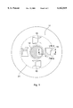
- FIG. 1 is a view of one side of the turbine disk showing the lugs which lock the turbine disk to a backup disk.
- FIG. 2 is an enlarged fragmentary view taken on line 2--2 of FIG. 1 showing the frontal view of the lug.
- FIG. 3 is an enlarged fragmentary view taken on line 3--3 of FIG. 1 showing a side view of the lug.
- FIG. 4 is an enlarged fragmentary view showing the composite disk sandwiched between two backup disks 16 and 17.
- FIG. 1 the face of a composite turbine disk 11 mounted on a shaft 12.
- the shaft 12 may drive the disk 11 or the disk 11 may drive the shaft 12.
- the composite disk is made up of a plurality of layers of a polar weave of carbon fibers.
- a polar weave is well known and consists of fibers (not shown) running in an annular direction woven with fibers running in radial directions. The layers of fibers are held in a rigid configuration in a ceramic matrix.
- the composite disk 11 is provided with a plurality of lugs 15 best shown in FIG. 1.
- These lugs 15 have generally trapezoidal configurations which when cut by a first plane parallel to the axis of the shaft 12 and when cut by a second plane perpendicular to the first plane, with both planes being normal to the disk and passing trough the lug.
- FIG. 2 shows the trapezoidal configuration of the lug when cut by the first plane.
- FIG. 3 shows the configuration of he lug 15 when cut by the second plane. This configuration offer the least stress raisers which can cause a failure of the composite disk 12.
- a pair of backup disks 16 and 17 are secured to the shaft 12 on opposite sides of the composite disk 11.
- One of the disks, 16, is provided with a recess 20 which is a negative of the lug 15 so that the lug fits snugly in the recess 20.
- Both of the backup disks 16 and 17 are attached to the shaft 12 so that, when a load is transmitted to or from the composite disk, the disks 11 and 16 cannot move away from each other.
- the lug 15 may be part of a three dimensionally woven insert 21 which is embedded in the composite disk 11 and held there by the ceramic matrix.
- the insert 21 consists of a thick layer of three dimensionally woven carbon fibers in a ceramic matrix. Three dimensional weaving is well known those skilled in the art of weaving.
- the ceramic matrix is formed by compressing the layers of woven carbon fibers into a heated preform and infiltrating the preform with methyltrichlorosilane. The preform is then further heated to decompose the methyltrichlorosilane to silicon carbide.
- the disk may be made of a ceramic material. Methods of casting ceramic materials are well known.
- carbon fibers specified above includes the use of either regular carbon fibers or graphite fibers.
Abstract
A load transferring system wherein a composite turbine disk mounted on a shaft is in contact with a backup disk which is secured to the shaft. The turbine disk is made of layers of woven carbon fibers held in a rigid configuration in a ceramic matrix. The composite disk has a plurality of lugs which have trapezoidal cross sections when cut by planes which are perpendicular to each other, with both planes being normal to the disk. The backup disk is provided with recesses which are the negative of the trapezoidal lugs to lock the two disks together. A second backup disk may be secured to the shaft to secure the composite turbine disk between the backup disks.
Description
This invention was made by an employee of the United States Government and may be manufactured and used by or for the Government without the payment of any royalties.
This invention relates to systems for transferring loads from a turbine shaft to a turbine disk and vice versa.
In turbomachinery it is usually necessary to attach turbine disks to a turbine shaft for either having the shaft drive the disk or the disk drive the shaft. Composite disks offer better results in some operations but are more sensitive to stress risers than metallic disks. Thus, it is sometimes necessary to secure a backup disk, having the required strength, to the shaft and provide some means for locking the composite disk to the backup disk.
Bolts have been used for locking the backup disk to the composite disk but the bolt holes in the composite disk are stress raisers which can eventually lead to failure of the composite disk. Other methods of attaching the backup disc to the composite turbine disk have other problems.
A load transferring system wherein a composite turbine disk mounted on a shaft is in contact with a backup disk which is secured to the shaft. The turbine disk is made of layers of woven graphite fibers held in a rigid configuration in a ceramic matrix. The composite disk has a plurality of lugs which have generally trapezoidal cross sections when cut by planes which are perpendicular to each other, with both planes being normal to the disk. The backup disk is provided with recesses which are the negative of the trapezoidal lugs to lock the two disks together. A second backup disk may be secured to the shaft to secure the composite turbine disk between the backup disks.
FIG. 1 is a view of one side of the turbine disk showing the lugs which lock the turbine disk to a backup disk.
FIG. 2 is an enlarged fragmentary view taken on line 2--2 of FIG. 1 showing the frontal view of the lug.
FIG. 3 is an enlarged fragmentary view taken on line 3--3 of FIG. 1 showing a side view of the lug.
FIG. 4 is an enlarged fragmentary view showing the composite disk sandwiched between two backup disks 16 and 17.
Referring now in detail to the drawings there is shown in FIG. 1 the face of a composite turbine disk 11 mounted on a shaft 12. Depending on the usage of the apparatus, the shaft 12 may drive the disk 11 or the disk 11 may drive the shaft 12. The composite disk is made up of a plurality of layers of a polar weave of carbon fibers. A polar weave is well known and consists of fibers (not shown) running in an annular direction woven with fibers running in radial directions. The layers of fibers are held in a rigid configuration in a ceramic matrix.
The composite disk 11 is provided with a plurality of lugs 15 best shown in FIG. 1. These lugs 15 have generally trapezoidal configurations which when cut by a first plane parallel to the axis of the shaft 12 and when cut by a second plane perpendicular to the first plane, with both planes being normal to the disk and passing trough the lug. FIG. 2 shows the trapezoidal configuration of the lug when cut by the first plane. FIG. 3 shows the configuration of he lug 15 when cut by the second plane. This configuration offer the least stress raisers which can cause a failure of the composite disk 12.
To lock the composite disk 11 to the shaft 12, a pair of backup disks 16 and 17 (FIG. 4) are secured to the shaft 12 on opposite sides of the composite disk 11. One of the disks, 16, is provided with a recess 20 which is a negative of the lug 15 so that the lug fits snugly in the recess 20. Both of the backup disks 16 and 17 are attached to the shaft 12 so that, when a load is transmitted to or from the composite disk, the disks 11 and 16 cannot move away from each other.
If desired for greater strength and resistance to delamination, the lug 15 may be part of a three dimensionally woven insert 21 which is embedded in the composite disk 11 and held there by the ceramic matrix. The insert 21 consists of a thick layer of three dimensionally woven carbon fibers in a ceramic matrix. Three dimensional weaving is well known those skilled in the art of weaving.
The ceramic matrix is formed by compressing the layers of woven carbon fibers into a heated preform and infiltrating the preform with methyltrichlorosilane. The preform is then further heated to decompose the methyltrichlorosilane to silicon carbide.
While a composite disk is described above, the disk may be made of a ceramic material. Methods of casting ceramic materials are well known.
Also, it should be understood that the use of carbon fibers specified above includes the use of either regular carbon fibers or graphite fibers.
Claims (4)
1. A load transferring system, comprising:
a turbine disk mounted on a turbine shaft having an axis, said turbine disk consists of a two-dimensional composite material, said turbine disk also having a load-transferring lug attached to one side thereof, said lug having generally trapezoidal cross sectional configurations when cut by a pair of planes perpendicular to each other and parallel to the shaft axis, said lug consists of a three-dimensional composite material,
a backup disk attached to said turbine shaft, said backup disk having a recess which is the negative of said lug on said turbine disk for receiving said lug to lock said turbine disk to said backup disk, and
means attached to said shaft for holding said backup disk and said turbine disk in contact with each other.
2. A load transferring system as recited in claim 1 wherein said composite material consists of carbon fibers in a ceramic matrix.
3. A load transferring system as recited in claim 1 wherein said composite material consists of graphite fibers in a ceramic matrix.
4. A load transferring system, comprising:
a turbine disk mounted on a turbine shaft having an axis, said turbine disk consists of a two-dimensional composite material,
a load-transferring lug integral with one side of said turbine disk, said load-transferring lug consists of a three-dimensional composite material such that composite fibers extend in a direction parallel to the axis,
a backup disk attached to said turbine shaft, said backup disk having a recess which is the negative of said lug on said turbine disk for receiving said lug to lock said turbine disk to said backup disk, and
means attached to said shaft for holding said backup disk and said turbine disk in contact with each other.
Priority Applications (1)
| Application Number | Priority Date | Filing Date | Title |
|---|---|---|---|
| US09/190,784 US6162019A (en) | 1998-11-12 | 1998-11-12 | Load transfer mechanism for a turbine disk |
Applications Claiming Priority (1)
| Application Number | Priority Date | Filing Date | Title |
|---|---|---|---|
| US09/190,784 US6162019A (en) | 1998-11-12 | 1998-11-12 | Load transfer mechanism for a turbine disk |
Publications (1)
| Publication Number | Publication Date |
|---|---|
| US6162019A true US6162019A (en) | 2000-12-19 |
Family
ID=22702766
Family Applications (1)
| Application Number | Title | Priority Date | Filing Date |
|---|---|---|---|
| US09/190,784 Expired - Fee Related US6162019A (en) | 1998-11-12 | 1998-11-12 | Load transfer mechanism for a turbine disk |
Country Status (1)
| Country | Link |
|---|---|
| US (1) | US6162019A (en) |
Cited By (3)
| Publication number | Priority date | Publication date | Assignee | Title |
|---|---|---|---|---|
| US6863759B2 (en) | 2001-01-24 | 2005-03-08 | M Cubed Technologies, Inc. | Methods for making composite bonded structures |
| US20160153463A1 (en) * | 2014-11-17 | 2016-06-02 | United Technologies Corporation | Fiber Reinforced Spacer for a Gas Turbine Engine |
| US20170138200A1 (en) * | 2015-07-20 | 2017-05-18 | Rolls-Royce Deutschland Ltd & Co Kg | Cooled turbine runner, in particular for an aircraft engine |
Citations (2)
| Publication number | Priority date | Publication date | Assignee | Title |
|---|---|---|---|---|
| US4363602A (en) * | 1980-02-27 | 1982-12-14 | General Electric Company | Composite air foil and disc assembly |
| US5205716A (en) * | 1990-10-02 | 1993-04-27 | Societe Europeenne De Propulsion | Composite material turbine wheel |
-
1998
- 1998-11-12 US US09/190,784 patent/US6162019A/en not_active Expired - Fee Related
Patent Citations (2)
| Publication number | Priority date | Publication date | Assignee | Title |
|---|---|---|---|---|
| US4363602A (en) * | 1980-02-27 | 1982-12-14 | General Electric Company | Composite air foil and disc assembly |
| US5205716A (en) * | 1990-10-02 | 1993-04-27 | Societe Europeenne De Propulsion | Composite material turbine wheel |
Non-Patent Citations (1)
| Title |
|---|
| Mitch Petervery, Boeing, Rocketdyne Division, Nov. 14, 1997 Wayne Lorandeau, DuPont Lanxide, Nov. 14, 1997 (See Enclosure). * |
Cited By (5)
| Publication number | Priority date | Publication date | Assignee | Title |
|---|---|---|---|---|
| US6863759B2 (en) | 2001-01-24 | 2005-03-08 | M Cubed Technologies, Inc. | Methods for making composite bonded structures |
| US20160153463A1 (en) * | 2014-11-17 | 2016-06-02 | United Technologies Corporation | Fiber Reinforced Spacer for a Gas Turbine Engine |
| US10648481B2 (en) * | 2014-11-17 | 2020-05-12 | United Technologies Corporation | Fiber reinforced spacer for a gas turbine engine |
| US20170138200A1 (en) * | 2015-07-20 | 2017-05-18 | Rolls-Royce Deutschland Ltd & Co Kg | Cooled turbine runner, in particular for an aircraft engine |
| US10436031B2 (en) * | 2015-07-20 | 2019-10-08 | Rolls-Royce Deutschland Ltd & Co Kg | Cooled turbine runner, in particular for an aircraft engine |
Similar Documents
| Publication | Publication Date | Title |
|---|---|---|
| US3936552A (en) | Nonmetallic composite friction member | |
| US3692150A (en) | Oxidation barrier for a carbon friction disc | |
| US5613578A (en) | Phase change brake disks | |
| EP0570466B1 (en) | Carbon composite brake disc with positive vibration damping | |
| US6193027B1 (en) | Friction unit | |
| US6025062A (en) | Cogged component for the mechanical transmission of force | |
| US7090057B2 (en) | Composite friction disc with structural core and refurbishable lining elements | |
| US20050084379A1 (en) | Compressor blade root for engine blades of aircraft engines | |
| US3473637A (en) | Metal supported carbon friction disc | |
| GB1561297A (en) | Transition reinforcement of composite blade dovetails | |
| EP0484366A1 (en) | Carbon composite laminated structure | |
| US6162019A (en) | Load transfer mechanism for a turbine disk | |
| KR950013725B1 (en) | Composite helicopter swashplate | |
| US3761231A (en) | Composite articles | |
| US6558785B1 (en) | Insulated reentry heat shield | |
| US11746843B2 (en) | Brake disc assembly | |
| US4119179A (en) | Brake disc structure | |
| Effinger | Load Transfer Mechanism for a Turbine Disk | |
| US4696376A (en) | Configuration for a disk brake torque tube | |
| JPS63266131A (en) | Fan blade support ring | |
| WO2021123755A1 (en) | Brake disc, method of manufacturing the same, and an insert | |
| US5635272A (en) | Composite structure for transmitting high shear loads | |
| CA1248882A (en) | Composite friction member | |
| US5652052A (en) | Bi-composite joint using continuous fiber | |
| JPS5861343A (en) | Leaf spring |
Legal Events
| Date | Code | Title | Description |
|---|---|---|---|
| AS | Assignment |
Owner name: NATIONAL AERONAUTICS AND SPACE ADMINISTRATION, DIS Free format text: ASSIGNMENT OF ASSIGNORS INTEREST;ASSIGNOR:EFFINGER, MICHAEL R.;REEL/FRAME:009585/0921 Effective date: 19981112 |
|
| REMI | Maintenance fee reminder mailed | ||
| LAPS | Lapse for failure to pay maintenance fees | ||
| STCH | Information on status: patent discontinuation |
Free format text: PATENT EXPIRED DUE TO NONPAYMENT OF MAINTENANCE FEES UNDER 37 CFR 1.362 |
|
| FP | Lapsed due to failure to pay maintenance fee |
Effective date: 20041219 |