US6164822A - Dual compartment stand-up pouch - Google Patents
Dual compartment stand-up pouch Download PDFInfo
- Publication number
- US6164822A US6164822A US09/501,855 US50185500A US6164822A US 6164822 A US6164822 A US 6164822A US 50185500 A US50185500 A US 50185500A US 6164822 A US6164822 A US 6164822A
- Authority
- US
- United States
- Prior art keywords
- package
- panel
- compartments
- compartment
- outer panel
- Prior art date
- Legal status (The legal status is an assumption and is not a legal conclusion. Google has not performed a legal analysis and makes no representation as to the accuracy of the status listed.)
- Expired - Lifetime
Links
Images
Classifications
-
- B—PERFORMING OPERATIONS; TRANSPORTING
- B65—CONVEYING; PACKING; STORING; HANDLING THIN OR FILAMENTARY MATERIAL
- B65D—CONTAINERS FOR STORAGE OR TRANSPORT OF ARTICLES OR MATERIALS, e.g. BAGS, BARRELS, BOTTLES, BOXES, CANS, CARTONS, CRATES, DRUMS, JARS, TANKS, HOPPERS, FORWARDING CONTAINERS; ACCESSORIES, CLOSURES, OR FITTINGS THEREFOR; PACKAGING ELEMENTS; PACKAGES
- B65D75/00—Packages comprising articles or materials partially or wholly enclosed in strips, sheets, blanks, tubes, or webs of flexible sheet material, e.g. in folded wrappers
- B65D75/52—Details
- B65D75/58—Opening or contents-removing devices added or incorporated during package manufacture
- B65D75/5861—Spouts
- B65D75/5872—Non-integral spouts
- B65D75/5883—Non-integral spouts connected to the package at the sealed junction of two package walls
-
- B—PERFORMING OPERATIONS; TRANSPORTING
- B65—CONVEYING; PACKING; STORING; HANDLING THIN OR FILAMENTARY MATERIAL
- B65D—CONTAINERS FOR STORAGE OR TRANSPORT OF ARTICLES OR MATERIALS, e.g. BAGS, BARRELS, BOTTLES, BOXES, CANS, CARTONS, CRATES, DRUMS, JARS, TANKS, HOPPERS, FORWARDING CONTAINERS; ACCESSORIES, CLOSURES, OR FITTINGS THEREFOR; PACKAGING ELEMENTS; PACKAGES
- B65D31/00—Bags or like containers made of paper and having structural provision for thickness of contents
- B65D31/12—Bags or like containers made of paper and having structural provision for thickness of contents with two or more compartments
-
- B—PERFORMING OPERATIONS; TRANSPORTING
- B65—CONVEYING; PACKING; STORING; HANDLING THIN OR FILAMENTARY MATERIAL
- B65D—CONTAINERS FOR STORAGE OR TRANSPORT OF ARTICLES OR MATERIALS, e.g. BAGS, BARRELS, BOTTLES, BOXES, CANS, CARTONS, CRATES, DRUMS, JARS, TANKS, HOPPERS, FORWARDING CONTAINERS; ACCESSORIES, CLOSURES, OR FITTINGS THEREFOR; PACKAGING ELEMENTS; PACKAGES
- B65D75/00—Packages comprising articles or materials partially or wholly enclosed in strips, sheets, blanks, tubes, or webs of flexible sheet material, e.g. in folded wrappers
- B65D75/008—Standing pouches, i.e. "Standbeutel"
-
- B—PERFORMING OPERATIONS; TRANSPORTING
- B65—CONVEYING; PACKING; STORING; HANDLING THIN OR FILAMENTARY MATERIAL
- B65D—CONTAINERS FOR STORAGE OR TRANSPORT OF ARTICLES OR MATERIALS, e.g. BAGS, BARRELS, BOTTLES, BOXES, CANS, CARTONS, CRATES, DRUMS, JARS, TANKS, HOPPERS, FORWARDING CONTAINERS; ACCESSORIES, CLOSURES, OR FITTINGS THEREFOR; PACKAGING ELEMENTS; PACKAGES
- B65D81/00—Containers, packaging elements, or packages, for contents presenting particular transport or storage problems, or adapted to be used for non-packaging purposes after removal of contents
- B65D81/32—Containers, packaging elements, or packages, for contents presenting particular transport or storage problems, or adapted to be used for non-packaging purposes after removal of contents for packaging two or more different materials which must be maintained separate prior to use in admixture
- B65D81/3261—Flexible containers having several compartments
-
- B—PERFORMING OPERATIONS; TRANSPORTING
- B65—CONVEYING; PACKING; STORING; HANDLING THIN OR FILAMENTARY MATERIAL
- B65D—CONTAINERS FOR STORAGE OR TRANSPORT OF ARTICLES OR MATERIALS, e.g. BAGS, BARRELS, BOTTLES, BOXES, CANS, CARTONS, CRATES, DRUMS, JARS, TANKS, HOPPERS, FORWARDING CONTAINERS; ACCESSORIES, CLOSURES, OR FITTINGS THEREFOR; PACKAGING ELEMENTS; PACKAGES
- B65D2575/00—Packages comprising articles or materials partially or wholly enclosed in strips, sheets, blanks, tubes or webs of flexible sheet material, e.g. in folded wrappers
- B65D2575/52—Details
- B65D2575/58—Opening or contents-removing devices added or incorporated during package manufacture
- B65D2575/583—Opening or contents-removing devices added or incorporated during package manufacture the non-integral spout having an elongate cross-sectional shape, e.g. canoe or boat shaped
-
- Y—GENERAL TAGGING OF NEW TECHNOLOGICAL DEVELOPMENTS; GENERAL TAGGING OF CROSS-SECTIONAL TECHNOLOGIES SPANNING OVER SEVERAL SECTIONS OF THE IPC; TECHNICAL SUBJECTS COVERED BY FORMER USPC CROSS-REFERENCE ART COLLECTIONS [XRACs] AND DIGESTS
- Y10—TECHNICAL SUBJECTS COVERED BY FORMER USPC
- Y10S—TECHNICAL SUBJECTS COVERED BY FORMER USPC CROSS-REFERENCE ART COLLECTIONS [XRACs] AND DIGESTS
- Y10S383/00—Flexible bags
- Y10S383/906—Dispensing feature
Definitions
- This invention relates generally to flexible packaging and more particularly to flexible packages for holding two paste-like or flowable materials in separate compartments for enabling the simultaneous dispensing of such materials from the package.
- Flexible containers formed of sheet materials have gained wide acceptance in the trade for holding food products or other air-perishable materials therein.
- One common type of flexible package container is the so-called "stand-up" package. That package is arranged to be filled and sealed to isolate the contents of the package from the ambient atmosphere.
- Such packages are formed from a web of flexible stock material, e.g., polyethylene, polyester, polypropylene, metal foil, and combinations thereof in single or multiple plies.
- a flexible package having a hollow interior including a pair of compartments for holding respective granular or powdered products isolated from each other.
- the package is formed of flexible sheet material and in one embodiment comprises a front panel, a rear panel, and an intermediate panel.
- the front and rear panels each have a top edge portion, a bottom edge portion, and a pair of sides which are connected together.
- the bottom edge portions of the front and rear panels are sealed together.
- the intermediate panel has a pair of side edges and a bottom edge portion, with one of the side edges sealed to the package along one of the sides, and the other of the side edges is peelably sealed to the rear panel in one embodiment and to the front panel in another embodiment.
- the top edge portion of the intermediate panel is permanently sealed to the top edge portion of one panel and is peelably sealed to the top edge portion of the other panel.
- the bottom edge portion of the intermediate panel is permanently sealed to the front and rear panels.
- the space between the intermediate panel and the panel to which is peelably secured forms one compartment and the space between the intermediate panel and the other panel forms the other compartment.
- a hand peelable seal extends across the top portion of the panels to releasably seal the materials within the compartments and to enable the package to be readily peeled open to simultaneously pour the contents of the compartments therefrom.
- a dispensing package formed of a flexible material, e.g., a plastic film or laminate, and comprising first and second separate compartments and an outlet, e.g., a dispenser in the form of a fitment having a removable cap, coupled to the two compartments.
- the first compartment has a first outer panel and a first inner panel.
- the second compartment has a second outer panel and a second inner panel.
- the first outer panel and the first inner panel of the first compartment each have a top portion, a pair of side marginal edges and a bottom edge.
- the bottom edge of the first outer panel and the first inner panel are secured, e.g., heat sealed or welded, together.
- the top portion of the first outer panel and the top portion of said first inner panel define a first passageway between them.
- the second outer panel and the second inner panel of the second compartment each have a top portion, a pair of side marginal edges and a bottom edge.
- the bottom edge of the second outer panel and the second inner panel are secured, e.g., heat sealed or welded, together.
- the top portion of the second outer panel and the top portion of the second inner panel define a second passageway between them.
- the side marginal edges of the first outer panel, the first inner panel, the second outer panel and the second inner panel are all secured, e.g., heat sealed or welded, together.
- the two compartments are juxtaposed with respect to each other, with the first and second inner panels being disposed in a confronting relationship with each other.
- the first and second inner panels are arranged to be spaced apart from each other, whereupon the bottom edge of the first compartment and the bottom edge of the second compartment form a wide, stable base for supporting the package in an upright orientation.
- the dispenser e.g., the fitment with the cap, is coupled to the two passageways and is arranged to enable the contents of the two compartments to be ejected, e.g., squeezed, from the package together.
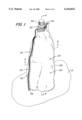
- FIG. 1 is an isometric view of a flexible package constructed in accordance with this invention and shown in its filled state;
- FIG. 2 is a reduced size plan view of one face of the package of FIG. 1;
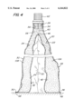
- FIG. 3 is an enlarged sectional view taken along line 3--3 of FIG. 1;
- FIG. 4 is an enlarged sectional view taken along line 4--4 of FIG. 1;
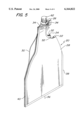
- FIG. 5 is an isometric view, partially broken away, showing the flexible package of FIG. 1 prior to being filled.
- the package is formed of a flexible material and is designed to hold two flowable materials or paste-like products 10A and 10B (FIGS. 3 and 4), such as two flavors of cake icing, in respective compartments 22 and 24 (to be described later) of the package to provide easy access to those products, e.g., dispensing, simultaneously through hand manipulation.
- the package 20 includes a port fitment 26 (also to be described later) which is coupled to the compartments 22 and 24 to enable the two paste-like products 10A and 10B to be dispensed simultaneously from the package through the fitment by squeezing the package.
- the package 20 provides the advantages of keeping the two products 10A and 10B separate from each other in a protected environment, while enabling them to be readily dispensed simultaneously through the fitment for mixing and use.
- the package 20 shown and described hereinafter is merely one of many possible configurations for packages constructed in accordance with this invention.
- the size, shape or product type(s) held within the package is merely exemplary and not limiting.
- the package 20 can be made of a variety of flexible materials, such as a variety of paper, plastic and/or foil materials, in single or multiple layers, as required by the product to be packaged, and provided that such materials can be thermally bonded, e.g., welded, in the manner well known to the flexible packaging industry.
- the package is in a shape somewhat like a stand-up pouch and is formed of sheets of plastic material.
- the package includes a front panel 28, a rear panel 30 and a bottom gusset panel 32.
- the front and rear panels are each of the same shape and their designation as being “front” or “rear” is arbitrary since either panel could be deemed to be the package's front or rear. Either or both of the panels may include indicia, e.g., printed matter, thereon, if desired.
- each of the panels 28 and 30 has a generally linear top edge 34, a generally linear bottom edge 36, and a pair of side edges 38 and 40.
- the lower portions of the side edges 38 and 40 are linear and extend perpendicularly upward from the bottom edge 36.
- the upper portions of the side edges 38 and 40 as best seen in FIG. 2 are linear but extend inward at an acute angle to the lower portions of the side edges and terminate at the top edge 34.
- the bottom gusset panel 32 (FIGS. 3 and 4), whose shape will be described hereinafter, is secured, e.g., welded, to the bottom edge 36 of the front panel 28 and to the bottom edge 36 of the rear panel 30.
- the gusset panel 32 includes two sections 42 and 44, each of which is of a similar shape to the front and rear panels 28 and 30. The two sections of the gusset panel 32 are connected at a top fold line 46.
- the bottom edge of each of the gusset panel sections 42 and 44 is designated by the reference number 48 (FIG. 4). It is these edges which are secured to the bottom edges 36 of the front and rear panels 28 and 30.
- the bottom edge 48 of the gusset panel section 42 is welded to the bottom edge 36 of the front panel 28.
- the bottom edge 48 of the gusset panel section 44 is welded to the bottom edge 36 of the rear panel 30.
- Each of the gusset panel sections 42 and 44 has a pair of side edges 50 and 52 which are shaped similarly to the side edges 38 and 40 of the front and rear panels 28 and 30, respectively.
- the side edges of the front panel are fixedly secured, e.g., welded, together.
- the side edge 38 of the front panel 28, the side edge 50 of the gusset panel section 42, the side edge 50 of the gusset panel section 44 and the side edge 38 of the rear panel 30 are all welded together along their entire lengths.
- the side edge 40 of the front panel 28, the side edge 52 of the gusset panel section 42, the side edge 52 of the gusset panel section 44 and the side edge 38 of the rear panel 30 are all welded together along their entire lengths.
- one compartment 22 is formed between the sealed marginal edges of the front panel 28 and the immediately adjacent gusset panel section 42.
- the other compartment 24 is formed between the sealed marginal edges of the rear panel 30 and the immediately adjacent gusset panel section 44.
- Each compartment includes a passageway at its upper end which communicate with each other, as will be described later.
- the port fitment 26 is of any conventional construction and basically comprises a canoe-shaped base 54 having a central passageway 56 (FIG. 4) extending vertically there-through and terminating at an open outlet port (not shown).
- the canoe-shaped base 54 of the fitment is welded in place between the upper edges 34 of the front and rear panels 28 and 30, respectively, with the portions of those panels extending beyond the fitment being welded to each other to seal the top of the package 20.
- the lower end of the central passageway 56 is in communication with the interior 58 (FIG. 4) of the package 20 immediately above the fold 46 of the gusset panel 32.
- the area 58 serves as a merger zone at which the open top portion or passageway of the compartment 22 and the open top portion or passageway of the compartment 24 meet.
- a cap 62 is provided on the fitment and is releasably secured, e.g., screwed, to the fitment over its outlet port.
- the cap 62 thus serves to close off the outlet port to prevent any of the paste-like materials within the package from leaking out of the outlet port.
- the fitment's cap 62 can be replaced (screwed in place) to seal the remaining products within the two compartments of the package.
- the bottom edge of the front panel 28 is not secured to the bottom edge of the rear panel 30 (the bottom edge of the font panel is secured to the bottom edge of the gusset section 42, and the bottom edge of the rear panel is secured to the bottom edge of the gusset section 44), the bottom of the package 20 has an "open" configuration.
- the bottom portion of the package's compartment 22 can be separated from the bottom portion of the package's compartment 24 (except for the marginal edges at which they are joined), whereupon the package can be arranged to form a "stand pouch.”
- the portions of the bottom of the package which are spread apart from each other can be used to form a wide stable base to support the package 20 in an upright position on any horizontal surface, like a shelf 12 as shown in FIG. 1.
- the package 20 can be constructed so that the two compartments 22 and 24 are physically isolated from each other within the package until their contents are to be dispensed.
- the fold line 46 of the gusset panel 32 may be weakly welded to either the front panel 28 or rear panel 30 to create a sealed compartment between the gusset panel and the front or rear panel.
- the weld, being weakened is adapted to be ruptured by the pressure produced when the package is squeezed to dispense the contents from the sealed chamber, whereupon the weld breaks to enable the contents of the once-sealed compartment to flow to the fitment where it meets with the contents of the other compartment and are dispensed together.
- the weld line can be permanent and not rupturable, but the gusset panel section adjacent the weld line can be weakened and rupturable, e.g., perforated, so that upon squeezing the weakened line ruptures to enable the contents of the compartment to flow out.
- the fitment can be configured to extend all the way to the dual compartment area of the package and can include two flow-through ports. One of such ports is in fluid communication with the interior of one compartment and the other port is in fluid communication with the interior of the other compartment.
- the two compartments can be physically isolated from each other, and their contents dispensed simultaneously through respective ports of the fitment.
- the package 20 may include a cut-off or tear-off dispensing mouth.
- the top portion of the package includes a weakened line extending transversely thereacross slightly below the top edge 34 and which can be torn to form an open mouth communicating with the zone 58 at the outlet of the two compartments 22 and 24.
- the package may include indicia or instructions to have the user sever the package along a line extending slightly below the top edge of the package to form an open mouth communicating with the zone 58 at the outlet of the two compartments 22 and 24.
- either of these fitment-less embodiments can make use a gusset panel either weakly welded to the front or rear panel or including a weakened line, as discussed above, to physically isolate the contents of the two chambers from each other until they are to be dispensed.
Abstract
Description
Claims (9)
Priority Applications (4)
| Application Number | Priority Date | Filing Date | Title |
|---|---|---|---|
| US09/501,855 US6164822A (en) | 2000-02-10 | 2000-02-10 | Dual compartment stand-up pouch |
| DE60122224T DE60122224D1 (en) | 2000-02-10 | 2001-02-06 | Two-roomed packaging |
| EP01301034A EP1123875B1 (en) | 2000-02-10 | 2001-02-06 | Dual compartment package |
| CA002335170A CA2335170C (en) | 2000-02-10 | 2001-02-09 | Dual compartment stand-up pouch |
Applications Claiming Priority (1)
| Application Number | Priority Date | Filing Date | Title |
|---|---|---|---|
| US09/501,855 US6164822A (en) | 2000-02-10 | 2000-02-10 | Dual compartment stand-up pouch |
Publications (1)
| Publication Number | Publication Date |
|---|---|
| US6164822A true US6164822A (en) | 2000-12-26 |
Family
ID=23995281
Family Applications (1)
| Application Number | Title | Priority Date | Filing Date |
|---|---|---|---|
| US09/501,855 Expired - Lifetime US6164822A (en) | 2000-02-10 | 2000-02-10 | Dual compartment stand-up pouch |
Country Status (4)
| Country | Link |
|---|---|
| US (1) | US6164822A (en) |
| EP (1) | EP1123875B1 (en) |
| CA (1) | CA2335170C (en) |
| DE (1) | DE60122224D1 (en) |
Cited By (50)
| Publication number | Priority date | Publication date | Assignee | Title |
|---|---|---|---|---|
| USD448988S1 (en) | 2001-02-08 | 2001-10-09 | Kapak Corporation | Stand-up pouch for holding liquids |
| EP1164092A2 (en) * | 2000-06-13 | 2001-12-19 | Mauro Zaninelli | A bag having heating or chilling means |
| USD453295S1 (en) | 2000-05-26 | 2002-02-05 | Kapak Corporation | Pouch for holding liquids |
| WO2002040353A1 (en) * | 2000-11-16 | 2002-05-23 | Colgate-Palmolive Company | Method of making dual chamber sachet |
| US20020166779A1 (en) * | 2001-03-15 | 2002-11-14 | The Procter & Gamble Company | Flexible multiple compartment pouch |
| US20030071059A1 (en) * | 2001-06-22 | 2003-04-17 | Tadashi Hagihara | Self-standing type bag-shaped container having evaluating and flow velocity controlling functions |
| US20030185469A1 (en) * | 2002-04-01 | 2003-10-02 | Knoerzer Anthony Robert | Package with internal pouch and method for making the same |
| FR2841537A1 (en) * | 2002-06-28 | 2004-01-02 | Soplaril Sa | MULTI-COMPARTMENT BAG |
| US6679304B1 (en) | 2002-06-04 | 2004-01-20 | Frank Vacca | Flexible refilling container |
| US6749090B2 (en) | 2001-10-22 | 2004-06-15 | Trek Bicycle Corporation | Dual bladder sports hydration system |
| US6752264B2 (en) | 2002-07-03 | 2004-06-22 | Sonoco Development, Inc. | Flexible pouch having system for mixing two components |
| US20040118710A1 (en) * | 2002-12-20 | 2004-06-24 | Bourque Raymond Anthony | Multiple compartment pouch and beverage container with frangible seal |
| US20040211980A1 (en) * | 2003-04-24 | 2004-10-28 | Sei-Hyung Ryu | Silicon carbide power devices with self-aligned source and well regions and methods of fabricating same |
| US6921203B2 (en) | 2002-11-12 | 2005-07-26 | Sonoco Development, Inc. | Stand-up pouch with legs |
| US20050173455A1 (en) * | 1998-12-22 | 2005-08-11 | Tadashi Hagihara | Structure for joining a sheet member and a tubular member in a pouch container |
| US20060144875A1 (en) * | 2004-12-29 | 2006-07-06 | Etesse Patrick J | Flexible container containing a liquid product, and a process for making a liquid-filled, flexible container |
| US20060213913A1 (en) * | 2005-03-24 | 2006-09-28 | Von Blucher Hasso | Drink receptacle, in particular drinking bag, composed of flexible composite material |
| US20070051746A1 (en) * | 2005-09-08 | 2007-03-08 | L'oreal | Packaging and dispenser device comprising an endpiece, and a flexible pouch fastened to the endpiece |
| US20070189641A1 (en) * | 2004-11-05 | 2007-08-16 | Mark Steele | Package Having a Fluid Actuated Closure |
| US20070262100A1 (en) * | 2006-04-28 | 2007-11-15 | Ppi Technologies, Inc. | Flexible pouch with a tube spout fitment and method of forming |
| US20070278114A1 (en) * | 2006-06-01 | 2007-12-06 | Kane James P | Multiple compartment pouch or container with frangible seal |
| US20080272146A1 (en) * | 2007-05-01 | 2008-11-06 | Daniel Steven Kaczmarek | Portable liquid-dispensing bag |
| US20080279485A1 (en) * | 2004-11-05 | 2008-11-13 | Mark Steele | Packages having fluid-filled chamber closures |
| US20090180716A1 (en) * | 2007-10-31 | 2009-07-16 | Mark Steele | Package handle |
| WO2010092413A2 (en) | 2009-02-16 | 2010-08-19 | Iris Vrus-Pervan | Precise hair dyeing set with hair lock fastener |
| US20110142376A1 (en) * | 2008-07-08 | 2011-06-16 | Morlot Severine | Closure element for a container made of particularly sheet type material |
| US20110170804A1 (en) * | 2010-01-13 | 2011-07-14 | Marc Mamiye | Slide dispensing sealed pouch |
| US8573445B2 (en) | 2006-04-28 | 2013-11-05 | Pouch Pac Innovations, Llc | Flexible pouch with a tube spout fitment and flexible sleeve |
| US20130318916A1 (en) * | 2011-02-21 | 2013-12-05 | Scaldopack Sprl. | Packaging for a liquid filling material, and method and device for producing it |
| US20150014356A1 (en) * | 2012-02-23 | 2015-01-15 | Bostik S.A. | Dispenser packaging for viscous liquid comprising large particles |
| US9376249B2 (en) | 2011-07-08 | 2016-06-28 | Mark Steele | Sanitary dispensing package |
| US20170080440A1 (en) * | 2014-01-27 | 2017-03-23 | Lindal France Sas | Two-channel dispensing device intended to close a vial |
| US9694945B2 (en) | 2013-11-14 | 2017-07-04 | Csm Bakery Products Na, Inc. | Fitment coupler with cap |
| US9963284B2 (en) | 2015-04-09 | 2018-05-08 | Mark Steele | Package valve closure system and method |
| US10266331B2 (en) | 2016-02-10 | 2019-04-23 | Anthony Pavlakovic | Apparatus for dispensing an adhesive |
| JP2019137437A (en) * | 2018-02-13 | 2019-08-22 | 凸版印刷株式会社 | Double-folded packaging container |
| US10442582B1 (en) | 2018-08-14 | 2019-10-15 | Phoenix Closures, Inc. | Spout fitment apparatus for a flexible container |
| US10507966B2 (en) | 2016-11-06 | 2019-12-17 | Innovationary Enterprises LLC | Straw accessible multiple compartment beverage pouch |
| US20200047967A1 (en) * | 2018-08-10 | 2020-02-13 | Miraclecorp Products | Unblended pet food product and method for making a pet food product |
| US11084628B2 (en) | 2017-03-02 | 2021-08-10 | Zip Top Llc | Flexible container with spouts and closure |
| US11098940B2 (en) * | 2019-03-08 | 2021-08-24 | Zip Top Llc | Flexible container with ice tray |
| US11155394B2 (en) | 2017-04-24 | 2021-10-26 | Dow Global Technologies Llc | Flexible container |
| US11198550B2 (en) * | 2017-04-24 | 2021-12-14 | Dow Global Technologies Llc | Flexible container |
| USD945826S1 (en) | 2017-09-19 | 2022-03-15 | Zip Top, Llc | Reusable sealable cup |
| USD945828S1 (en) | 2017-09-19 | 2022-03-15 | Zip Top, Llc | Reusable sealable cup |
| USD945827S1 (en) | 2017-09-19 | 2022-03-15 | Zip Top, Llc | Reusable sealable cup |
| US11377267B2 (en) | 2019-05-15 | 2022-07-05 | Phoenix Closures, Inc. | Choke-resistant closure |
| US11479398B2 (en) * | 2018-04-26 | 2022-10-25 | Dow Global Technologies Llc | Method for sealing a fitment to a flexible container and flexible container comprising a fitment |
| USD1004428S1 (en) * | 2021-11-29 | 2023-11-14 | Kolmar Korea Co., Ltd. | Spout for packaging container |
| US11883835B2 (en) | 2016-12-22 | 2024-01-30 | Conopco, Inc. | Shell container suitable for housing a discrete refill container |
Families Citing this family (1)
| Publication number | Priority date | Publication date | Assignee | Title |
|---|---|---|---|---|
| CN103057811A (en) * | 2013-02-01 | 2013-04-24 | 杨浩东 | Upright packaging bag |
Citations (16)
| Publication number | Priority date | Publication date | Assignee | Title |
|---|---|---|---|---|
| US3980222A (en) * | 1973-11-13 | 1976-09-14 | The Procter & Gamble Company | Longitudinally partitioned tubular body |
| FR2351870A1 (en) * | 1974-06-26 | 1977-12-16 | Thimonnier & Cie | Multiple flexible plastics container - may be filled from one filling point and is separated before use |
| US4256256A (en) * | 1979-04-30 | 1981-03-17 | American Can Company | Multiple compartment pouch and method of making same |
| US4732299A (en) * | 1986-02-10 | 1988-03-22 | Hoyt Earl E | Collapsible container |
| US4795271A (en) * | 1987-12-11 | 1989-01-03 | W. A. Lane, Inc. | Free standing product pouch |
| US4805767A (en) * | 1987-06-18 | 1989-02-21 | Newman Duncan A C | Package system |
| US4886373A (en) * | 1987-08-17 | 1989-12-12 | Corella Arthur P | Self-supporting, flexible, dispensing package |
| US5114044A (en) * | 1990-06-15 | 1992-05-19 | Spanek Jr George | Multiple sleeve pastry tube |
| US5265961A (en) * | 1991-09-13 | 1993-11-30 | Mobil Oil Corporation | Plastic grocery bag having draw-tape closure and flat bottom |
| US5350240A (en) * | 1990-06-01 | 1994-09-27 | S. C. Johnson & Son, Inc. | Stand-up pouch having cross-seal feature and method of making |
| US5353927A (en) * | 1993-02-24 | 1994-10-11 | Illinois Tool Works Inc. | Plural compartment package |
| US5407278A (en) * | 1993-12-10 | 1995-04-18 | Fres-Co System Usa, Inc. | Dual compartment easily openable flexible package |
| US5714023A (en) * | 1996-02-23 | 1998-02-03 | Wheaton Holdings, Inc. | Method for sealing two compartment containers |
| US5860743A (en) * | 1996-11-27 | 1999-01-19 | The Coca-Cola Company | Stable flexible pouch and method for making the pouch |
| US5882120A (en) * | 1996-09-06 | 1999-03-16 | Kapak Corp. | Bag construction for distributing material |
| US5921440A (en) * | 1997-09-03 | 1999-07-13 | Maines; Morris P. | Multi-compartment container and adjustable dispenser |
Family Cites Families (5)
| Publication number | Priority date | Publication date | Assignee | Title |
|---|---|---|---|---|
| US2015972A (en) * | 1932-11-24 | 1935-10-01 | Sodergren Andreas Bernhard | Arrangement for mixing two different substances |
| US2593608A (en) * | 1948-07-08 | 1952-04-22 | Teepack Spezialmaschinen G M B | Folded bag |
| US3469768A (en) * | 1964-08-27 | 1969-09-30 | Dow Chemical Co | Dual compartment container |
| WO1998033717A1 (en) * | 1997-01-31 | 1998-08-06 | S.C. Johnson Home Storage, Inc. | Multicompartment thermoplastic bag |
| JP2000264344A (en) * | 1999-03-15 | 2000-09-26 | Dainippon Printing Co Ltd | Multi-chamber type pouch |
-
2000
- 2000-02-10 US US09/501,855 patent/US6164822A/en not_active Expired - Lifetime
-
2001
- 2001-02-06 DE DE60122224T patent/DE60122224D1/en not_active Expired - Lifetime
- 2001-02-06 EP EP01301034A patent/EP1123875B1/en not_active Expired - Lifetime
- 2001-02-09 CA CA002335170A patent/CA2335170C/en not_active Expired - Lifetime
Patent Citations (16)
| Publication number | Priority date | Publication date | Assignee | Title |
|---|---|---|---|---|
| US3980222A (en) * | 1973-11-13 | 1976-09-14 | The Procter & Gamble Company | Longitudinally partitioned tubular body |
| FR2351870A1 (en) * | 1974-06-26 | 1977-12-16 | Thimonnier & Cie | Multiple flexible plastics container - may be filled from one filling point and is separated before use |
| US4256256A (en) * | 1979-04-30 | 1981-03-17 | American Can Company | Multiple compartment pouch and method of making same |
| US4732299A (en) * | 1986-02-10 | 1988-03-22 | Hoyt Earl E | Collapsible container |
| US4805767A (en) * | 1987-06-18 | 1989-02-21 | Newman Duncan A C | Package system |
| US4886373A (en) * | 1987-08-17 | 1989-12-12 | Corella Arthur P | Self-supporting, flexible, dispensing package |
| US4795271A (en) * | 1987-12-11 | 1989-01-03 | W. A. Lane, Inc. | Free standing product pouch |
| US5350240A (en) * | 1990-06-01 | 1994-09-27 | S. C. Johnson & Son, Inc. | Stand-up pouch having cross-seal feature and method of making |
| US5114044A (en) * | 1990-06-15 | 1992-05-19 | Spanek Jr George | Multiple sleeve pastry tube |
| US5265961A (en) * | 1991-09-13 | 1993-11-30 | Mobil Oil Corporation | Plastic grocery bag having draw-tape closure and flat bottom |
| US5353927A (en) * | 1993-02-24 | 1994-10-11 | Illinois Tool Works Inc. | Plural compartment package |
| US5407278A (en) * | 1993-12-10 | 1995-04-18 | Fres-Co System Usa, Inc. | Dual compartment easily openable flexible package |
| US5714023A (en) * | 1996-02-23 | 1998-02-03 | Wheaton Holdings, Inc. | Method for sealing two compartment containers |
| US5882120A (en) * | 1996-09-06 | 1999-03-16 | Kapak Corp. | Bag construction for distributing material |
| US5860743A (en) * | 1996-11-27 | 1999-01-19 | The Coca-Cola Company | Stable flexible pouch and method for making the pouch |
| US5921440A (en) * | 1997-09-03 | 1999-07-13 | Maines; Morris P. | Multi-compartment container and adjustable dispenser |
Cited By (76)
| Publication number | Priority date | Publication date | Assignee | Title |
|---|---|---|---|---|
| US20050173455A1 (en) * | 1998-12-22 | 2005-08-11 | Tadashi Hagihara | Structure for joining a sheet member and a tubular member in a pouch container |
| US7284681B2 (en) | 1998-12-22 | 2007-10-23 | Tadashi Hagihara | Structure for joining a sheet member and a tubular member in a pouch container |
| USD453295S1 (en) | 2000-05-26 | 2002-02-05 | Kapak Corporation | Pouch for holding liquids |
| USD454487S1 (en) | 2000-05-26 | 2002-03-19 | Kapak Corporation | Pouch for holding liquids |
| USD455645S1 (en) | 2000-05-26 | 2002-04-16 | Kapak Corporation | Pouch for holding liquids |
| EP1164092A2 (en) * | 2000-06-13 | 2001-12-19 | Mauro Zaninelli | A bag having heating or chilling means |
| EP1164092A3 (en) * | 2000-06-13 | 2003-12-03 | Perissinotto, Raffaele | A bag having heating or chilling means |
| US6662530B1 (en) | 2000-11-16 | 2003-12-16 | Colgate-Palmolive Company | Method of making dual chamber sachet |
| WO2002040353A1 (en) * | 2000-11-16 | 2002-05-23 | Colgate-Palmolive Company | Method of making dual chamber sachet |
| USD448988S1 (en) | 2001-02-08 | 2001-10-09 | Kapak Corporation | Stand-up pouch for holding liquids |
| US20020166779A1 (en) * | 2001-03-15 | 2002-11-14 | The Procter & Gamble Company | Flexible multiple compartment pouch |
| EP1241112A3 (en) * | 2001-03-15 | 2003-02-26 | The Procter & Gamble Company | Flexible multiple compartment pouch |
| US6851578B2 (en) * | 2001-06-22 | 2005-02-08 | Tadashi Hagihara | Self-standing type bag-shaped container having evaluating and flow velocity controlling functions |
| US20030071059A1 (en) * | 2001-06-22 | 2003-04-17 | Tadashi Hagihara | Self-standing type bag-shaped container having evaluating and flow velocity controlling functions |
| US6749090B2 (en) | 2001-10-22 | 2004-06-15 | Trek Bicycle Corporation | Dual bladder sports hydration system |
| US6679630B2 (en) * | 2002-04-01 | 2004-01-20 | Recot, Inc. | Self-standing package and method for making the same |
| US20030185469A1 (en) * | 2002-04-01 | 2003-10-02 | Knoerzer Anthony Robert | Package with internal pouch and method for making the same |
| WO2003084828A1 (en) * | 2002-04-01 | 2003-10-16 | Frito-Lay North America, Inc. | Self-standing package and method for making the same |
| US6679304B1 (en) | 2002-06-04 | 2004-01-20 | Frank Vacca | Flexible refilling container |
| FR2841537A1 (en) * | 2002-06-28 | 2004-01-02 | Soplaril Sa | MULTI-COMPARTMENT BAG |
| WO2004002852A1 (en) * | 2002-06-28 | 2004-01-08 | Soplaril | Multicompartment bag |
| US6752264B2 (en) | 2002-07-03 | 2004-06-22 | Sonoco Development, Inc. | Flexible pouch having system for mixing two components |
| US6921203B2 (en) | 2002-11-12 | 2005-07-26 | Sonoco Development, Inc. | Stand-up pouch with legs |
| US7055683B2 (en) | 2002-12-20 | 2006-06-06 | E. I. Du Pont De Nemours And Company | Multiple compartment pouch and beverage container with smooth curve frangible seal |
| US20040118710A1 (en) * | 2002-12-20 | 2004-06-24 | Bourque Raymond Anthony | Multiple compartment pouch and beverage container with frangible seal |
| EP2204338A1 (en) | 2002-12-20 | 2010-07-07 | E. I. du Pont de Nemours and Company | Multiple compartment pouch and beverage container with frangible seal |
| US7306095B1 (en) | 2002-12-20 | 2007-12-11 | E. I. Du Pont De Nemours And Company | Multiple compartment pouch and beverage container with frangible seal |
| US20040211980A1 (en) * | 2003-04-24 | 2004-10-28 | Sei-Hyung Ryu | Silicon carbide power devices with self-aligned source and well regions and methods of fabricating same |
| US7883268B2 (en) | 2004-11-05 | 2011-02-08 | Mark Steele | Package having a fluid actuated closure |
| US20080279485A1 (en) * | 2004-11-05 | 2008-11-13 | Mark Steele | Packages having fluid-filled chamber closures |
| US20070189641A1 (en) * | 2004-11-05 | 2007-08-16 | Mark Steele | Package Having a Fluid Actuated Closure |
| US8613547B2 (en) | 2004-11-05 | 2013-12-24 | Mark Steele | Packages having bubble-shaped closures |
| US20060144875A1 (en) * | 2004-12-29 | 2006-07-06 | Etesse Patrick J | Flexible container containing a liquid product, and a process for making a liquid-filled, flexible container |
| US7674042B2 (en) * | 2005-03-24 | 2010-03-09 | Blucher Gmbh | Drink receptacle, in particular drinking bag, composed of flexible composite material |
| US20060213913A1 (en) * | 2005-03-24 | 2006-09-28 | Von Blucher Hasso | Drink receptacle, in particular drinking bag, composed of flexible composite material |
| US20070051746A1 (en) * | 2005-09-08 | 2007-03-08 | L'oreal | Packaging and dispenser device comprising an endpiece, and a flexible pouch fastened to the endpiece |
| US8573445B2 (en) | 2006-04-28 | 2013-11-05 | Pouch Pac Innovations, Llc | Flexible pouch with a tube spout fitment and flexible sleeve |
| US20070262100A1 (en) * | 2006-04-28 | 2007-11-15 | Ppi Technologies, Inc. | Flexible pouch with a tube spout fitment and method of forming |
| US20070278114A1 (en) * | 2006-06-01 | 2007-12-06 | Kane James P | Multiple compartment pouch or container with frangible seal |
| US9061819B2 (en) | 2006-06-01 | 2015-06-23 | E I Du Pont De Nemours And Company | Multiple compartment pouch or container with frangible seal |
| US20080272146A1 (en) * | 2007-05-01 | 2008-11-06 | Daniel Steven Kaczmarek | Portable liquid-dispensing bag |
| US7896199B2 (en) * | 2007-05-01 | 2011-03-01 | Daniel Steven Kaczmarek | Portable liquid-dispensing bag |
| US20090180716A1 (en) * | 2007-10-31 | 2009-07-16 | Mark Steele | Package handle |
| US20110142376A1 (en) * | 2008-07-08 | 2011-06-16 | Morlot Severine | Closure element for a container made of particularly sheet type material |
| US8528758B2 (en) * | 2008-07-08 | 2013-09-10 | Seaquist Closures France | Closure element for a container made of particularly sheet type material |
| WO2010092413A2 (en) | 2009-02-16 | 2010-08-19 | Iris Vrus-Pervan | Precise hair dyeing set with hair lock fastener |
| US20110170804A1 (en) * | 2010-01-13 | 2011-07-14 | Marc Mamiye | Slide dispensing sealed pouch |
| US20130318916A1 (en) * | 2011-02-21 | 2013-12-05 | Scaldopack Sprl. | Packaging for a liquid filling material, and method and device for producing it |
| US20170029174A1 (en) * | 2011-07-08 | 2017-02-02 | Mark Steele | Sanitary dispensing package |
| US10583968B2 (en) * | 2011-07-08 | 2020-03-10 | Mark Steele | Sanitary dispensing package |
| US9376249B2 (en) | 2011-07-08 | 2016-06-28 | Mark Steele | Sanitary dispensing package |
| US20150014356A1 (en) * | 2012-02-23 | 2015-01-15 | Bostik S.A. | Dispenser packaging for viscous liquid comprising large particles |
| US9327894B2 (en) * | 2012-02-23 | 2016-05-03 | Bostik S.A. | Dispenser packaging for viscous liquid comprising large particles |
| US9694945B2 (en) | 2013-11-14 | 2017-07-04 | Csm Bakery Products Na, Inc. | Fitment coupler with cap |
| US20170080440A1 (en) * | 2014-01-27 | 2017-03-23 | Lindal France Sas | Two-channel dispensing device intended to close a vial |
| US9908127B2 (en) * | 2014-01-27 | 2018-03-06 | Lindal France Sas | Two-channel dispensing device intended to close a vial |
| US10301093B2 (en) | 2015-04-09 | 2019-05-28 | Illinois Tool Works Inc. | Package valve closure system and method |
| US9963284B2 (en) | 2015-04-09 | 2018-05-08 | Mark Steele | Package valve closure system and method |
| US10266331B2 (en) | 2016-02-10 | 2019-04-23 | Anthony Pavlakovic | Apparatus for dispensing an adhesive |
| US10507966B2 (en) | 2016-11-06 | 2019-12-17 | Innovationary Enterprises LLC | Straw accessible multiple compartment beverage pouch |
| US11883835B2 (en) | 2016-12-22 | 2024-01-30 | Conopco, Inc. | Shell container suitable for housing a discrete refill container |
| US11383890B2 (en) | 2017-03-02 | 2022-07-12 | Zip Top Llc | Silicone molding process for making a container with zipper members tapered at a flexible spout |
| US11358755B2 (en) | 2017-03-02 | 2022-06-14 | Zip Top Llc | Flexible foodstuff container with closure |
| US11084628B2 (en) | 2017-03-02 | 2021-08-10 | Zip Top Llc | Flexible container with spouts and closure |
| US11198550B2 (en) * | 2017-04-24 | 2021-12-14 | Dow Global Technologies Llc | Flexible container |
| US11155394B2 (en) | 2017-04-24 | 2021-10-26 | Dow Global Technologies Llc | Flexible container |
| USD945826S1 (en) | 2017-09-19 | 2022-03-15 | Zip Top, Llc | Reusable sealable cup |
| USD945828S1 (en) | 2017-09-19 | 2022-03-15 | Zip Top, Llc | Reusable sealable cup |
| USD945827S1 (en) | 2017-09-19 | 2022-03-15 | Zip Top, Llc | Reusable sealable cup |
| JP2019137437A (en) * | 2018-02-13 | 2019-08-22 | 凸版印刷株式会社 | Double-folded packaging container |
| US11479398B2 (en) * | 2018-04-26 | 2022-10-25 | Dow Global Technologies Llc | Method for sealing a fitment to a flexible container and flexible container comprising a fitment |
| US20200047967A1 (en) * | 2018-08-10 | 2020-02-13 | Miraclecorp Products | Unblended pet food product and method for making a pet food product |
| US10442582B1 (en) | 2018-08-14 | 2019-10-15 | Phoenix Closures, Inc. | Spout fitment apparatus for a flexible container |
| US11098940B2 (en) * | 2019-03-08 | 2021-08-24 | Zip Top Llc | Flexible container with ice tray |
| US11377267B2 (en) | 2019-05-15 | 2022-07-05 | Phoenix Closures, Inc. | Choke-resistant closure |
| USD1004428S1 (en) * | 2021-11-29 | 2023-11-14 | Kolmar Korea Co., Ltd. | Spout for packaging container |
Also Published As
| Publication number | Publication date |
|---|---|
| EP1123875A2 (en) | 2001-08-16 |
| EP1123875B1 (en) | 2005-10-12 |
| CA2335170C (en) | 2005-05-17 |
| DE60122224D1 (en) | 2006-09-28 |
| CA2335170A1 (en) | 2001-08-10 |
| EP1123875A3 (en) | 2003-08-13 |
Similar Documents
| Publication | Publication Date | Title |
|---|---|---|
| US6164822A (en) | Dual compartment stand-up pouch | |
| AU661109B2 (en) | Stress concentrator aperture-forming means for sealed containers and packages | |
| US3171581A (en) | Dispensing flexible bag | |
| US6641307B2 (en) | Pouch having a branched chamber | |
| KR950011151B1 (en) | Asymmetric stress concentrator for a dispenser package | |
| US9802745B2 (en) | Pour channel with cohesive closure valve and locking bubble | |
| EP0078761A2 (en) | Container having a pressure-rupturable seal for dispensing contents | |
| WO2003070585A1 (en) | Beverage container punch | |
| JPH04503345A (en) | upright storage bag | |
| WO2008020590A1 (en) | Branch type standing pouch | |
| CA2427065A1 (en) | Flexible pouch having dispensing nozzle and frangible seal | |
| US6439792B1 (en) | Device for dispensing a seasoning | |
| JP5725586B2 (en) | Paper outer container for liquid filling packaging | |
| US20040136620A1 (en) | Stand-up pouch | |
| JP4826096B2 (en) | Branch type standing pouch | |
| AU2016325593A1 (en) | Liner for a vessel | |
| US20220340350A1 (en) | Easy To Open Package With Controlled Dispensing Device | |
| JPH04503044A (en) | upright storage bag | |
| US20040007490A1 (en) | Food package | |
| JPH04503045A (en) | upright storage bag | |
| EP2502849A1 (en) | Multi-chamber, individually accessible pouch for content dispensing | |
| WO2017127477A1 (en) | Package with rupturable opening | |
| JPH08310558A (en) | Stress concentration open hole forming means for sealed container and package | |
| US20230399160A1 (en) | Container for Consumable Substances with Integrated Utensil | |
| WO1996015040A1 (en) | Pouch with reinforcing means for delivery tube |
Legal Events
| Date | Code | Title | Description |
|---|---|---|---|
| AS | Assignment |
Owner name: FRES-CO SYSTEM USA, INC., PENNSYLVANIA Free format text: ASSIGNMENT OF ASSIGNORS INTEREST;ASSIGNOR:BEER, JEFFREY SCOTT;REEL/FRAME:010603/0181 Effective date: 20000207 |
|
| STCF | Information on status: patent grant |
Free format text: PATENTED CASE |
|
| AS | Assignment |
Owner name: FLOE, WAYNE G., MINNESOTA Free format text: ASSIGNMENT OF ASSIGNORS INTEREST;ASSIGNOR:JIROSEL CORPORATION;REEL/FRAME:013184/0306 Effective date: 20020703 |
|
| FPAY | Fee payment |
Year of fee payment: 4 |
|
| FPAY | Fee payment |
Year of fee payment: 8 |
|
| FPAY | Fee payment |
Year of fee payment: 12 |